Table of Contents
Advertisement
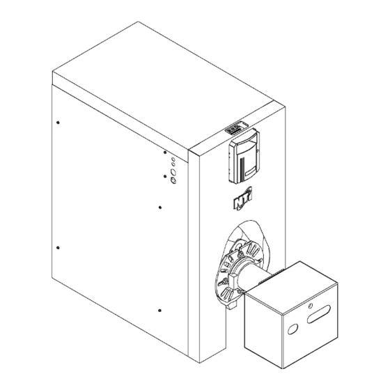
Odyssey
Model Numbers: CT80-250
Version Date: 2013-03-15
INSTALLATION AND OPERATION INSTRUCTIONS
ODYSSEY OIL BOILER
Venting Applications: Natural Draft or Direct Vent (Balanced Flue)
TABLE OF CONTENTS
1.0
INTRODUCTION ............................................................................................................... 3
2.0
SPECIFICATIONS.............................................................................................................. 6
3.0
BOILER LOCATION.......................................................................................................... 8
4.0
BOILER ASSEMBLY......................................................................................................... 9
5.0
GENERAL VENTING ...................................................................................................... 14
6.0
NATURAL DRAFT APPLICATIONS............................................................................. 15
7.0
DIRECT VENT APPLICATIONS .................................................................................... 19
8.0
BOILER PIPING ............................................................................................................... 26
9.0
FIELD WIRING ................................................................................................................ 28
10.0 INSTALLATION CHECKLIST ....................................................................................... 34
11.0 ANNUAL MAINTENANCE AND INSPECTION .......................................................... 36
12.0 PARTS LIST ..................................................................................................................... 39
13.0 WARRANTY .................................................................................................................... 43
HAZARD SYMBOLS AND DEFINITIONS
Danger Sign: Indicates a hazardous situation which, if not avoided, will result in
serious injury or death.
Warning Sign: Indicates a hazardous situation which, if not avoided, could result
in serious injury or death.
Caution Sign plus Safety Alert Symbol: Indicates a hazardous situation which, if
not avoided, could result in minor or moderate injury.
Caution Sign without Safety Alert Symbol: Indicates a hazardous situation
which, if not avoided, could result in property damage.
Notice Sign: Indicates a hazardous situation which, if not avoided, could result
in property damage.
This Boiler must be installed by a licensed and trained Heating Technician or
the Warranty is Void. Failure to properly install this unit may result in
property damage, serious injury to occupants, or possibly death.
NEW - OUTDOOR SENSOR
Meets Sept. 2012 requirements for
"Automatic Means"
Odyssey CT80-250
H
NTI # 84944
Advertisement
Table of Contents

Subscribe to Our Youtube Channel
Summary of Contents for Odyssey CT80-250
-
Page 1: Table Of Contents
Odyssey NEW – OUTDOOR SENSOR Meets Sept. 2012 requirements for “Automatic Means” Model Numbers: CT80-250 Version Date: 2013-03-15 INSTALLATION AND OPERATION INSTRUCTIONS ODYSSEY OIL BOILER Venting Applications: Natural Draft or Direct Vent (Balanced Flue) TABLE OF CONTENTS INTRODUCTION ....................... 3 SPECIFICATIONS...................... - Page 2 Low Water Cut Off (LWCO) - To take advantage of the HydroStat’s LWCO feature, the Odyssey is equipped with a special immersion well call the Electro-well™. Failure to use the Electro-well™ provided with the boiler will over-ride the LWCO feature and allow the boiler to operate during low water conditions which may result in over heating, fire, serious injury, or death.
-
Page 3: Introduction
Introduction - Installation & Operation Instructions 1.0 INTRODUCTION General Installation Requirements The installation of your NTI Odyssey oil boiler shall be in accordance with these instructions and the regulations of the authorities having jurisdiction and must comply with the following codes and standards: United States... - Page 4 Failure to follow these instructions will result in serious injury or death. Blocked Vent Switch - All Natural Draft Odyssey boilers require a Blocked Vent Switch which is factory supplied and packaged with the burner kit and is mandatory in Canada.
- Page 5 Introduction - Installation & Operation Instructions Direct Vent Applications There are four Odyssey models, CT90-120, certified for installation as a Direct Vent boiler. This balanced flue system requires a special venting system in order to pressurize and essentially equalize the inlet and outlet pressure to ensure normal operation.
-
Page 6: Specifications
For proper operation, there must be enough natural or mechanical draft. Due to the design of the Odyssey, it may operate at a positive over fire pressure up to +.20 at -.03 draft. Due to installation and equipment variations, recommended air settings are a guideline and will require alteration. See Tables 2-1 and 2-2. - Page 7 Specifications - Installation & Operation Instructions Direct Vent Application Draft Settings (Direct Vent) - Due to the design of the balanced flue system, the Odyssey will operate at a positive draft pressure and a positive over fire pressure at all times. It is designed to operate with a maximum stack draft of 0.25”...
-
Page 8: Boiler Location
CT80-250 3.0 BOILER LOCATION In all cases, the Odyssey must be installed indoors in a dry location where the ambient temperature must be maintained above freezing and below 100°F [38°C]. All boiler components must be protected from dripping, spraying water, or rain during operation and servicing. Consider the proximity to the following when determining the best boiler location. -
Page 9: Boiler Assembly
│ Odyssey C 85-340 Boiler Assembly - Installation & Operation Instructions 4.0 BOILER ASSEMBLY The installation of the boiler shall be in accordance with the authorities having jurisdiction and must comply with Standard CSA B139 (Canada) or NFPA 31 (USA). - Page 10 │ Odyssey Installation and Operation Instructions - General Venting CT80-250 Figure 4-3 Tighten Bracket Nuts (Rear) Figure 4-4 Front Brackets Tighten nuts, top and bottom, to secure the rear brackets to the boiler. Bottom Figure 4-5 Mount Front Brackets Figure 4-6 Tighten Bracket Nuts (Front)
- Page 11 │ Odyssey C 85-340 Boiler Assembly - Installation & Operation Instructions Figure 4-9 Attach HydroStat 3250 Bracket Figure 4-10 Attach Back Panels & Electro-well Recommend installing Hold Down Control Panel top back after flue Bracket breeching connected and sealed. HydroStat 3250 Secure bottom back panel.
- Page 12 Burner Installation The Odyssey boiler is designed to work with burners described in this manual. The use of other nozzles, and/or burners, may cause unsafe operation and will void any and all responsibility by NY Thermal for the safety and reliability of the system.
- Page 13 │ Odyssey C 85-340 Boiler Assembly - Installation & Operation Instructions Figure 4-5 Burner Installation Prepare the burner as per the burner manufacturer’s instructions. Refer to Tables 2-1 to 2-3 for nozzle sizes, burner settings, insertion depths, air settings, and specifications.
-
Page 14: General Venting
Due to the design of the Odyssey it may operate at a positive over fire pressure up to +.20 at a -.03 draft. -
Page 15: Natural Draft Applications
│ Odyssey CT80-250 Natural Draft - Installation & Operation Instructions 6.0 NATURAL DRAFT APPLICATIONS Natural Draft Rules and Guidelines 1. Acceptable Venting Material - Use vent material approved by National Standards NFPA 31 (USA) or CSA B139 (Canada) and local codes. - Page 16 │ Odyssey Installation and Operation Instructions - Natural Draft CT80-250 Sizing Combustion Air Openings The following sections detail the three (3) methods for determining the minimum opening size and location required for providing combustion air: 1. Indoor Air - Opening Sizes: Older buildings typically have sufficient ventilation due to air leakage around single pane windows, poorly weather-stripped doors, and non-existent vapour barrier.
- Page 17 For proper operation, there must be enough natural or mechanical draft. Due to the design of the Odyssey, it may operate at a positive over fire pressure up to +.20 at -.03 draft. 9. Draft Gauge (if applicable) - A barometric control can be used to adjust the draft opening by installing it in the breeching.
- Page 18 │ Odyssey Installation and Operation Instructions - Natural Draft CT80-250 Table 6-1 Minimum Chimney Sizes Minimum Minimum Minimum I=B=R Chimney Boiler Flue Model Breaching Chimney Collar Size Rectangular Round Diameter Height 6 " 15 ' C100 C120 5 " 8 " x 8 "...
-
Page 19: Direct Vent Applications
│ Odyssey CT80-250 Direct Vent - Installation & Operation Instructions 7.0 DIRECT VENT APPLICATIONS Direct Vent Rules and Guidelines 1. Vent Material: Use approved venting material. Refer to Direct Vent Termination Kit in this section. 2. Continuous Vent: The vent must be in one continuous piece with no joints. - Page 20 Direct Venting Rules and Guidelines, and Figure 7-1. The instructions detailed in this section are a combination of Odyssey specific and National Code restrictions. Compliance alone doesn’t ensure a satisfactory installation as good common sense must also be applied. Failure to follow these instructions may result in fire, property damage, serious injury or death.
- Page 21 │ Odyssey CT80-250 Direct Vent - Installation & Operation Instructions Figure 7-1 Termination Clearance Quick Reference Diagram...
- Page 22 │ Odyssey Installation and Operation Instructions - Direct Vent CT80-250 Direct Vent Termination Kit When installed as a Direct Vent boiler the combustion air-inlet must also be piped directly to the outdoors using the methods described in this section and in accordance with the CSA B139 (Canada) or NFPA 31 (USA) and local code requirements.
- Page 23 │ Odyssey CT80-250 Direct Vent - Installation & Operation Instructions Direct Vent Installation Instructions Vent Location - Under normal operating conditions, the boiler will vent plumes of white flue gases; therefore, code restrictions and potential hazards associated with thru-wall installations should be considered before selecting a location for the Direct Vent terminal.
- Page 24 H. Perform steps D-G to install the 3” adapter #81098 over the 3” vent terminal, and tighten gear clamp. Fold the vent terminal heat shield flaps back into position. J. Refer to Figure 7-7 for an illustration of a typical balanced flue installation for an Odyssey boiler (CT90-120).
- Page 25 │ Odyssey CT80-250 Direct Vent - Installation & Operation Instructions Figure 7 -6 Seal with silicone where shown. Step B Step G 5” to 3” Ported Adapter Smoke Hood Insulated Flex Step D Step E Step F Step C Important Warning - It is the responsibility of the installing contractor to ensure that: 1.
-
Page 26: Boiler Piping
BOILER PIPING Boiler Water Pressure - Odyssey boilers are intended to solely for use in pressurized closed-loop heating systems operating with a “fill pressure” between 12-15 psi at the boiler outlet and a Relief Valve pressure of 30 psi (maximum working pressure of the boiler). - Page 27 │ Odyssey CT80-250 Field Wiring - Installation & Operation Instructions Figure 8-1 Near Boiler Piping Central Heat Relief Valve Outlet Tridicator Heating * Circulator location Supply may vary from one application to another. Pump * Automatic Air Vent Air Eliminator (mandatory)
-
Page 28: Field Wiring
│ Odyssey Installation and Operation Instructions - Field Wiring CT80-250 FIELD WIRING All wiring and electrical grounding must be in accordance with local codes and the applicable National Electrical Code, NFPA 70 (USA) or CSA C22.2 (Canada). Ensure that the wiring complies with this manual. - Page 29 CT80-250 Field Wiring - Installation & Operation Instructions Figure 9-1 Odyssey Wiring Diagram Burner Primary Safety - The Blocked Vent Switch and any other limit device must break power to the burner primary (B1). Failure to follow these instructions may result in...
- Page 30 Low Water Cut Off (LWCO) - To take advantage of the HydroStat’s LWCO feature, the Odyssey is equipped with a special immersion well call the Electro-well™. Failure to use the Electro-well™ provided with the boiler will over-ride the LWCO feature and allow the boiler to operation during low water conditions which may result in over heating, fire, serious injury, or death.
- Page 31 │ Odyssey CT80-250 Field Wiring - Installation & Operation Instructions LO TEMP: o Minimum permissible boiler temperature, burner will fire without demand when temperature drops below the LO TEMP setting. o Controller inhibits circulator operation (120V outputs at C1 and ZC are deactivated) until the temperature exceeds the LO TEMP setting.
- Page 32 │ Odyssey Installation and Operation Instructions - Field Wiring CT80-250 Inferring Heat Load (“Automatic Means” of Adjusting Boiler Temperature) The HydroStat control incorporates two (2) options for Inferring Heat Load: 1) Thermal Targeting Method – default method 2) Outdoor Reset Method – method used when outdoor sensor is connected to OR and C 1) Thermal Targeting Method: Default method for satisfying central heat demands.
- Page 33 │ Odyssey CT80-250 Field Wiring - Installation & Operation Instructions 2) Outdoor Reset Method: Automatically active when the Outdoor Sensor is connected to the OR and C spade connects on the Fuel Smart HydroStat. Outdoor Reset overrides Thermal Targeting Method.
-
Page 34: Installation Checklist
│ Odyssey Installation and Operation Instructions - Installation Checklist CT80-250 10.0 INSTALLATION CHECKLIST Start-up 1. Close automatic air vent and boiler drain cock. 2. Boiler water pH range should be 7.0 - 8.5. If conditions are above 7, contact local water treatment company. - Page 35 │ Odyssey CT80-250 Installation Checklist - Installation & Operation Instructions Adjusting Combustion Air Smoke Pump - A reliable, certified smoke pump is required to correctly set up this equipment. Combustion Analyzer - To calibrate burner operation, use a calibrated combustion analyzer...
-
Page 36: Annual Maintenance And Inspection
Annual Cleaning Instructions Annually, before the heating season begins (fall) or immediately after it ends (spring), the Odyssey is to be cleaned and serviced by a licensed burner technician. If the burner is not used for an extended period of time, it must also be cleaned before being put back into service (start-up). - Page 37 │ Odyssey CT80-250 Maintenance - Installation & Operation Instructions Cleaning the Flue Passages: 1. Remove power from boiler before servicing. 2. Close oil supply valves. 3. Remove the front cover and the burner door (see Figure 12-1 for boiler parts breakout).
- Page 38 CT80-250 Handling Instructions Fiberglass and Ceramic Fiber Materials - Odyssey boilers use insulating materials to reduce heat exchanger losses and clearances to combustibles. It is important for installers and service personnel to know what these materials are, where they are located on the boiler, and how they should be handled. Refer to Table 11-1 for recommended handling instructions and Figure 12-1 for location of insulating materials.
-
Page 39: Parts List
│ Odyssey CT80-250 Parts List - Installation & Operation Instructions 12.0 PARTS LIST For a list of parts that corresponds to the item numbers in the callouts, refer to Table 12-1. Note that some item numbers may appear more than once in the parts list depending on which model number is being referenced. - Page 40 │ Odyssey Installation and Operation Instructions - Parts List CT80 -180 Figure 12-2 Burner Package Item 21: Burner and Included with Burner Kit blast tube are sold as a fully assembled unit. Burner Burner Gasket Flange Burner Mounting Hardware: M8 bolts, washers, and nuts used to mount the burner to the boiler Items 19 &...
- Page 41 │ Odyssey CT80-250 Parts List - Installation & Operation Instructions Table 12-1 Odyssey Parts List: Item Part # Models Description CT80. CT80-100 Boiler Only, CT80 (3 section) CT120-180 Boiler Only, CT120 (5 section) CT120. CT215-250 Boiler Only, CT215 (7 section) CT215.
- Page 42 │ Odyssey Installation and Operation Instructions - Parts List CT80 -180 Item Part # Models Description CT80-250 Brackets, Rear - Right CT80-250 Brackets, Front - Left CT80-250 Brackets, Front - Right CT80-250 Control Panel, HydraStat CT80-250 Hold Down Bracket, HydraStat...
-
Page 43: Warranty
13.0 WARRANTY A licensed and trained Heating Technician must install this appliance, otherwise the Warranty is VOID. FREE extended coverage Option C, only IF you register your boiler and installation with NY Thermal Inc. within the first year of purchase. What Is Covered We, the manufacturer, warrant that any parts or components of each new Boiler or Water Heater, will be supplied free of defects in material or workmanship. - Page 44 5. We care about the quality of service you receive, so please let us know if you have complaints concerning your authorized service representative. For Service Contact: Name: ____________________________________ Warranty Registration Form Odyssey Oil Boiler Owner’s Name Address City Province / State...
Need help?
Do you have a question about the CT80-250 and is the answer not in the manual?
Questions and answers