
Related Manuals for GRASS VALLEY Kayak

Summary of Contents for GRASS VALLEY Kayak
- Page 1 Kayak DIGITAL PRODUCTION SWITCHER User Manual SOFTWARE VERSION 6.9.1 071844705 MAY 2007...
- Page 2 Affiliate with the N.V. KEMA in The Netherlands CERTIFICATE Certificate Number: 510040.001 The Quality System of: Grass Valley, Inc. 400 Providence Mine Road 15655 SW Greystone Ct. 10 Presidential Way Nevada City, CA 95945 Beaverton, OR 97006 Floor, Suite 300...
- Page 3 Kayak DIGITAL PRODUCTION SWITCHER User Manual SOFTWARE VERSION 6.9.1 071844705 MAY 2007...
- Page 4 Benelux/Belgium: +32 (0) 2 334 90 30 Benelux/Netherlands: +31 (0) 35 62 38 42 1 N. Europe: +45 45 96 88 70 Germany, Austria, Eastern Europe: +49 6150 104 444 UK, Ireland, Israel: +44 118 923 0499 Copyright © Grass Valley. All rights reserved. This product may be covered by one or more U.S. and foreign patents.
-
Page 5: Table Of Contents
Introduction ............Kayak System Configuration Overview ........ -
Page 6: Size
Kayak DD Aux Busses ........ -
Page 7: Spin And Rotation Relationship
Overview Kayak-100 Panel ........ -
Page 8: Storing
Deleting Snapshots and Timelines ........Kayak — User Manual... - Page 9 Menu and Panel Interactions ......... Section 5 — Kayak Menu Summaries .
-
Page 10: Digipots
Transform Menus ..........Kayak — User Manual... -
Page 11: Slits Mode
Catalog of Effects ........... Kayak — User Manual... -
Page 12: Naming
C4fx for Kayak HD™ System ........ -
Page 13: Sidepanel Glossary
Key Main Menu ........... . Kayak — User Manual... -
Page 14: Converting
Setup ............Kayak — User Manual... - Page 15 GPI Index Card........... Kayak — User Manual...
- Page 16 ..............Kayak — User Manual...
-
Page 17: Preface
Preface About This Manual This Kayak User Manual includes Kayak HD and DD information and is designed as a reference manual for operators of Kayak Production Switcher systems. Standard Documentation Set The standard Kayak HD/DD documentation set consists of: • User Manual •... - Page 18 Preface Kayak — User Manual...
-
Page 19: Section 1 - System Overview
• Kayak HD 200C, which includes a 2 M/E Control Panel and a 4 RU Video Processor Frame frame equipped with two M/E modules • Kayak HD 200, which includes a 2 M/E Control Panel and a 8 RU Video Processor Frame frame equipped with two M/E modules •... -
Page 20: Kayak Dd Switcher Models
Section 1 — System Overview Kayak DD Switcher Models Two models are available: Kayak DD-1 One M/E production switcher with the following features: • Switch able between 525-line and 625-line formats • Fully digital 10-bit, 4:2:2 inputs, outputs, and video processing •... -
Page 21: Kayak
• Remote monitoring support via optional NetCentral software • Four keyers, each with linear, luminance and optional Chromatte™ chroma key functionality per M/E • Optional RGB color correction • Four channels of high-end digital effects (Option) per M/E Kayak — User Manual... -
Page 22: Kayak Hd Standard Features
.5 M/E includes cuts and mixes, no wipes or iDPM, with simple linear/lumi- nance keyers and no chroma keys. • Number of inputs: • 24 to 48 for Kayak HD 100C, 150C • 48 for Kayak HD 200C, 250C • 48 to 96 for Kayak HD 200, 250 •... -
Page 23: Kayak Hd Options
Introduction • GPI (General Purpose Interface) inputs: • Eight to 16 for Kayak HD 100C, 150C • 16 for Kayak HD 200C, 250C • 16-32 for Kayak HD 200, 250 • 24-32 for Kayak HD 300, 350 • GPI/Tally Outputs: •... -
Page 24: Supported Control Protocols
Mode with A/B background mix and four Lin/Lum keyers • Full M/E Upgrade Option. Adds one Mix/Effects module to any Kayak HD chassis. Order one or more options to get the total M/Es required. The 4RU chassis holds up to two M/E modules and/or I/O Expander modules. -
Page 25: System Components
System Components System Components Kayak Control Surfaces Kayak Production Switcher systems use a control panel with an integrated menu display (color TFT with touch-screen). The Sidepanel program, which runs on a user-supplied Windows PC, can also be used to control the Kayak system. -
Page 26: 1.5 And 2 M/E Control Panel
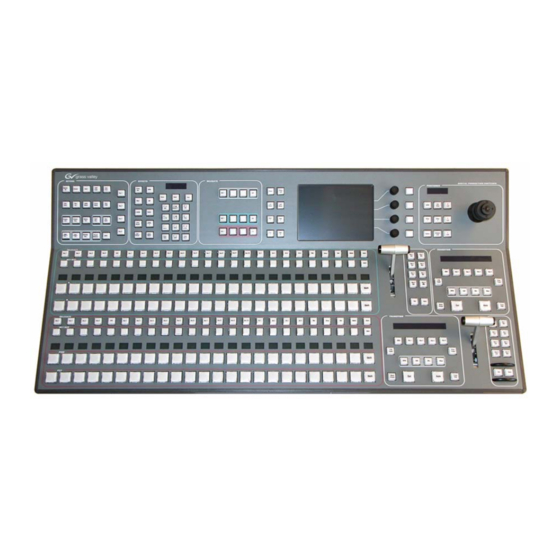
Section 1 — System Overview 1.5 and 2 M/E Control Panel Figure 3. Kayak 2 M/E Control Panel Positioner Subpanel Keyers Subpanel Delegation Subpanel Graphical Display Effect Subpanel Menu Navigation Buttons Digipots and Menu Buttons M/E1 M/E1 Transition Lever M/E1... -
Page 27: 2.5 And 3M/E Control Panel
System Components 2.5 and 3M/E Control Panel Figure 5. Kayak HD 250C, 250, and 300 Control Panel Figure 6. 3 M/E Control Panel, Rear View KAYAK DIGITAL PRODUCTION SWITCHER DC POWER IN RED. DC POWER IN RS 485 RS 232 48V/1.3A max. -
Page 28: Kayak Video Processor Frames
Section 1 — System Overview Kayak Video Processor Frames Kayak HD 4 RU Frame Figure 7. Kayak 4RU Frame, Front View with Door Removed Top M/E Slot Controller Flash Power Reset 2 USB Bottom M/E Slot M/E 0 (PP) (and 0.5 M/E) -
Page 29: Kayak Hd 8 Ru Frame
System Components Kayak HD 8 RU Frame Figure 8. Kayak 8RU Frame, Front View with Door Removed Fan Assembly Flash Power Reset RS-232 2 USB Air Fi Memory Switch Button Keyboard (unused) M/E 0 (PP) M/E 1 Controller (and 0.5 M/E) -
Page 30: Kdd-Psu Power Supply Option
KDD-PSU Power Supply Option The KDD-PSU option is a one-rack unit, wide range AC power supply pro- viding power for a remotely-mounted Kayak Control Panel or for each additional Control Panel connected to the same processor chassis. Power output is sufficient for two 1 M/E systems or one 2 M/E system. -
Page 31: Video Signal Flow
Video Signal Flow The basic video signal flow (Figure 11 on page 32) of the Kayak system has been designed for operational flexibility. For example, all the outputs from the M/E are routed back to the video crosspoint matrix, making all these signals accessible to the entire system. - Page 32 White Σ Float 2 Key Key Σ Σ & Analog HD Reference Digital Reference Float 2 Bkg Mixer Σ Σ Sync Generator Float 1 Mix Timing Analyzer Analog SD Reference Float 2 Mix Σ Timing Analyzer Kayak — User Manual...
- Page 33 Video Signal Flow Figure 12. KayakDD Vidoe Signal Flow Main Board RY 3910 ME: Single Mixer Effect (Plug-In Board) RY 3930 iDPM Video Proc PP: Single Mixer Effect (Plug-In Board) RY 3720 iDPM Video Proc Proc Kayak — User Manual...
- Page 34 Section 1 — System Overview Kayak — User Manual...
-
Page 35: Section 2 - Concepts
The Kayak Digital Production Switcher is designed for operational flexi- bility, and can be configured to fit various applications. Different Kayak systems can have different capabilities, or the same Kayak system can be re- configured to have different capabilities at different times. -
Page 36: Installation (Engineering Setups)
• Personality Setting (settings that give the operator the ability to cus- tomize his individual work surface to meet his personal preferences). All Kayak settings are non-volatile. Disk save and load operations are available via the Sidepanel Program that allows users to store configura- tion information on the hard disk of a PC or on a movable media for easy transport and for use as backup copies. -
Page 37: Personal Settings
Kayak HD Incoming video signals are connected to the Kayak HD system via BNC connectors on the rear of the Kayak HD Digital Processor frame. All inputs are serial digital (SMPTE 274M, SMPTE 296M, SMPTE RP211). Signals from external devices not operating in this standard will need to be converted. -
Page 38: Kayak Dd
Kayak HD system can control (Router, DPM, DDR). For a Kayak HD Digital Production Switcher, the term source refers to all the video signals and other attributes associated with a device. This is a funda- mental concept. The Kayak HD system is based on sources, not input signals or crosspoints. -
Page 39: Button Assignment (Source To Button Mapping)
For details on how to assign sources to buttons please refer to the Kayak Installation and Service Manual. Note E-MEM effects store Source IDs, not the source select buttons, so remapping sources does not change the appearance of recalled effects. - Page 40 For a Kayak system, the terms source button and source bus will be used. These terms better reflect a system operating philosophy that is source rather than crosspoint based.
-
Page 41: Shifted Sources
For example, on the Kayak HD-100 system, up to 28 sources can be mapped at one time, 14 to the unshifted source selection, and 14 to the shifted but- tons. -
Page 42: Mix/Effects (M/E) Stage
Section 2 — Concepts Mix/Effects (M/E) Stage Each M/E of the Kayak system can create a composite of two or more pic- tures. It includes multiple source selection buses and provides transition (mix and wipe) and keying capabilities on the selected signals. -
Page 43: Utility Bus
Mix/Effects (M/E) Stage The Kayak system M/E actually has four keyers, each handling a fill and a key signal, and it can accept three background sources (A, B, and Utility). Providing individual source selection rows for each bus is impractical, as the panel would become too large. -
Page 44: Kayak Hd Outputs
AUX Bus outputs may also be used for special purposes. Kayak HD AUX Busses and Output Assignments Kayak HD switchers provide 12 outputs per M/E. This means you can have up to 24 outputs in the compact frame and up to 48 in the large frame. -
Page 45: Resource Sharing And Point Of Use
However, changing the pattern shape affects both locations. Transition A transition is a change from one image to another. The Kayak system sup- ports three basic types of transitions: • Cut •... -
Page 46: Cut
Full Additive Mix Full Additive Mix (FAM) is a special mix transition that the Kayak system supports besides normal crossfade transitions. Picture elements in FAM transitions are composited differently through the time of the transition. -
Page 47: Wipes
(position, aspect ratios, edge attributes, etc.). Each Kayak M/E has two separate transition wipe systems, each of which can be assigned a different wipe pattern and be adjusted independently. These systems can each use one of the two available complex wipe pattern generators with advanced capabilities. -
Page 48: Transition Rate
It is also possible to manually control transitions using a lever arm. On the Kayak system, one transition rate can be assigned to the main tran- sition of the M/E. This type of transition can be controlled by that M/E’s lever arm. -
Page 49: Key Priority And Transitions
Key Priority and Transitions The four keyers on a Kayak M/E can be assigned priorities. This deter- mines the layering of the keys. The highest priority key appears on top, while keyers with lower priority may be partially or fully hidden behind those with higher key priorities. -
Page 50: Matte Fill Key Example
• Linear Key • Chroma Key • Preset Pattern The Kayak system also supports self keys and split keys. Matte Fill Key Example One of the earliest keying techniques was to use an art card and camera to perform a luminance key with a matte fill. This type of key is a good example for explaining basic keying principles because three separate and independent incoming signals are used. -
Page 51: Shaping Video
Video shaped with a different key cut signal will not key correctly. The appropriate key mode for this type of signal is the Linear key or Lumi- nance Key. Kayak — User Manual... -
Page 52: Key Control Signal Adjustment
Gain to suppress any imperfections in the incoming key signals. Setting Gain too high can cause ragged key edges. The Kayak system provides two methods for adjusting the key control signal, Clip and Gain, and Clip Hi and Clip Lo. Note that the same basic keying process is controlled by either of these methods. -
Page 53: High Gain, Low Gain, And Unity Gain
Low Gain Unity Gain On the Kayak system, Gain has a percentage value. A Gain value of 50% requires a luminance change of 50% of the distance between black and white to produce a keying signal ranging from transparent to opaque. A gain value of 100% (unity gain) uses the entire range between black and white for this transparent to opaque transition. -
Page 54: S-Shaped Key Signals
Low changes both Clip and Gain, not just Gain. S-Shaped Key Signals On the Kayak system, an S-shaping function is applied to the edges of lumi- nance keys. S-shaping smooths the sharp corners of a luminance key control signal, which helps prevent banding artifacts. S-shaping a signal minimally affects the key edges, and does not move key thresholds or affect the overall gain of the key. -
Page 55: Additional Keying Controls
(typically a key fill signal delivered via the Utility bus). With the Kayak RAM Recorder (Still Store), the mask signal can be a frozen page of video or a key fill. Complex mask shapes are often easier to draw by hand than to create with multiple wipe patterns. -
Page 56: Coring
(watermarks). The level of the key cut signal determines where and how deeply the hole will be cut into the background. The intended soft edge and translucency of the key can then be faithfully reproduced. Kayak — User Manual... - Page 57 The soft edges in the illustrations in this part of the manual are simulated. The key edges are actually gradients, which allows these edges to blend smoothly with the background. In the Kayak System the Linear Key is just a special parameter setup of the Luminance Key...
-
Page 58: Luminance Key And Self Key
(video only) Luminance Key Key Fill Clip and Gain (or Clip Hi/Lo) controls for luminance keys offer wide adjustment ranges. On the Kayak system, an S-shaping function is also applied to the edges of luminance keys. Kayak — User Manual... -
Page 59: Chroma Key
Background refers to the scene that will replace the backing color (same as a linear or luminance key) in the final picture. Background does not refer to the back- drop of the foreground scene. Kayak — User Manual... -
Page 60: Primary And Secondary Color Suppression
This is called an additive chroma key (used when the Kayak system Fore- ground Reshaping feature is off). When conditions do not permit adequate backing color suppression, the foreground with its backing color sup- pressed can be multiplied by the keying signal to prevent contaminating areas of the background outside the keyed area. -
Page 61: Preset Pattern
Pattern Key Cut Background with Preset Pattern Inserted Key Fill Split Key A split key uses an alternative key cut signal for keying. On the Kayak system, a key split is performed by holding down the button and Key Split selecting the desired key cut signal. -
Page 62: Properly And Improperly Shaped Video
Figure 27. Video and Key Signals from DPM When the shaping is done properly (using either shaped (Additive Key) or unshaped (Luminance Key) key fill) the desired output is the result (Figure 24 on page 58). Figure 28. Correctly Shaped DPM Key Example Kayak — User Manual... - Page 63 When the DPM provides an unshaped video output but the key is pro- cessed as though it were shaped, excessive luminance occurs where the key fill video and key hole edges overlap, producing a white halo around the key. Additive Key was used for unshaped key fill signal. Kayak — User Manual...
-
Page 64: Downstream Keyers (Half M/E And Dsk Option)
(as part of the Half M/E and DSK Upgrade). These DSKs can be coupled to any M/E in the system to operate downstream of that M/E. The DSKs do not support chroma keys or DPM effects. Kayak — User Manual... -
Page 65: Flexible Chroma Keyers
3-D Digital Effects Concepts The Kayak Digital Picture Manipulator options provide 3-D planar image translation and transformation from within each M/E of the Kayak system. Image translation has special basic concepts and terminology you should understand in order to get the most out of using the option. -
Page 66: Rotate
Scaling the X or Y components of the picture. X axis changes affect hori- zontal size, Y axis changes affect vertical size (Figure 35). Z axis changes affect both X and Y dimensions, and is the same as Size. Kayak — User Manual... -
Page 67: Skew
Axis Off Screen Center of Picture Center of Picture Source and Target Space The Kayak Digital Picture Manipulator uses source and target space frames of reference. • Source space for a control channel uses that channel’s coordinate system for reference. - Page 68 Section 2 — Concepts same transform may be difficult to understand and control. Kayak Digital Picture Manipulator effects can also employ both source and target space directed transforms simultaneously, which can create complex and beau- tiful effects. The simplest example for source and target space concerns a channel that has been rotated while the global channel remains unchanged.
-
Page 69: Post Transform Space
Figure 41. Post Transform Translation X Axis Translation X Axis Translation with Locate 3-D with Post Xform Kayak — User Manual... -
Page 70: Front And Back, Near And Far
This distinction can be important when, for example, different sources are being selected for different sides of an effect. The Kayak system uses a Near and Far convention to ease system opera- tion. Near is always the side of the picture that is visible (facing toward the viewer), and Far is the hidden side of the picture (facing away from the viewer). -
Page 71: Screen Coordinates
3-D Digital Effects Concepts Screen Coordinates The Kayak Digital Picture Manipulator accommodates two different aspect ratios, 4 x 3 and 16 x 9, selectable via the Video Standards menu. In 4 x 3 mode, the screen is six units high and eight units wide. In 16 x 9 mode, the screen is 18 units high and 32 units wide. -
Page 72: Size
Aspect Aspect values are in percentage of the original size, with 1.0 = 100%, 0.5 = 50%, etc. Perspective Perspective supports values from 0-100, with 0.06 as the default in 4x3 operation and 0.015 in 16x9. Kayak — User Manual... -
Page 73: Spin And Rotation Relationship
This nesting provides increased control of the effect dynamics. Source and Target space also affects the transform nesting order. Figure 44. Spin and Rotate Transform Nesting Spin Rotate Rotate Spin Source Source Target Target Kayak — User Manual... -
Page 74: Path Control
Kayak system interpolates parameter values between keyframes (in- betweening). The trajectory, or path, a manipulated picture travels between keyframes is determined by how these in-between values are interpolated. The Kayak system offers you several path controls (Figure 45 on page 74): •... -
Page 75: Tension, Continuity, And Bias Controls
The first keyframe (KF1) is the upper left square; the last keyframe (KF3) is the lower right square. The adjustments in these examples are applied to the middle keyframe only (KF2). Kayak — User Manual... -
Page 76: Path Vectors
The path through KF2 is parallel to an imaginary line drawn between KF1 and KF3. Figure 46. Path Vectors Tension Vector – Bias Vector – Continuity Vector Vector Values Path vector setting values of ± 1.0 are available, same as the Thomson Grass Valley Kaleidoscope DPM. Kayak — User Manual... -
Page 77: Tension Control
Tension vector is shortened to non-existence through KF2 (Figure 48). The path enters and leaves the middle keyframe in a straight line as it takes on an S-Linear motion; decelerating as it enters the middle keyframe and accelerating as it leaves. Kayak — User Manual... - Page 78 (Figure 49). The longer path will appear to make the image speed up through KF2 as it travels from KF1 to KF3. Figure 49. Tension Control Setting - 1.0 Tension Vector Tension = -1.0 Kayak — User Manual...
-
Page 79: Continuity Control
The effect of 1.0 continuity is that of motion dropping into and then out of the keyframe, similar to a bouncing ball (Figure 50 on page 79). Figure 51. Continuity Control Setting 1.0 Continuity Vector – Continuity = 1.0 Kayak — User Manual... - Page 80 With continuity set to -1.0, the paths between the keyframes become straight lines, accelerating into the keyframe and decelerating as it leaves the keyframe. Figure 52. Continuity Control Setting - 1.0 Continuity Vector – Continuity = -1.0 Kayak — User Manual...
-
Page 81: Bias Control
With the bias set to 1.0, the path is pulled towards the following keyframe. Entry into and exit from the keyframe is a straight line from the previous keyframe, and the path of the effect travels completely through KF2 before turning towards KF3. Kayak — User Manual... - Page 82 With the bias set to -1.0, the path is pulled towards the previous keyframe. Entry into and exit from the keyframe is a straight line to the following key- frame. Figure 55. Bias Control Setting - 1.0 Tension Exit Bias Vector Bias = -1.0 Kayak — User Manual...
-
Page 83: Sure Touch
The essential result is this: When an effect is recalled in a safe touch mode, only those values which underwent changes after the first key-frame of the original effect are touched, and only changes in values are applied. Kayak — User Manual... -
Page 84: Parallel Mode Example
Figure 56. Parallel Mode Example KF-1 KF-2 KF-1 KF-2 Now suppose that the image is centered and size = 30%. Next, effect 3 is recalled in sure touch “parallel” mode. The result would look like this: Kayak — User Manual... -
Page 85: Converge Mode Example
• Effect 2: Starts with the image centered and 30% size. Image is spun off screen to the right and down • Keyframe 1: size = 30% • Keyframe 2: locate X = 8.0, locate Y = -6.0, spin Z = 1.875. Figure 57. Converge Mode Example KF-1 KF-2 Kayak — User Manual... - Page 86 The effect converges towards the original effect over the dura- tion of the effect. The final keyframe of the effect would set the location and spin Z to exactly the same values as in the original effect. Figure 58. Converge Mode Example (continued) KF-1 KF-2 Kayak — User Manual...
-
Page 87: Comparing Parallel And Converge Modes
(red) and converge mode (green) is shown here. Figure 60. Comparing Parallel and Converge Modes (continued) KF-3 KF-1 KF-2 Obviously, there are ways to use sure touch which would create a bad result, as in the red case. Kayak — User Manual... - Page 88 Section 2 — Concepts Kayak — User Manual...
-
Page 89: Section 3 - Control Panels
• The positioner subpanel in the upper right provides easy positioning of DPM, wipes, and pattern keys. • The separate buttons in the bottom right section allow keyer Cut/Auto control independent from the transition section. Figure 61. Overview Kayak-100 Control Panel Graphical Display Positioner Subpanel Gra phical Display Positioner Digipots and... -
Page 90: Overview Kayak-200 Panel
• Transition control for M/1 and P/P are handled in the right sections of the panel. • The separate buttons on the right of the transition lever allow Cut/Auto keyer control independent from the transition section. Figure 62. Overview Kayak-200 Control Panel Effects Subpanel Delegation Menu Navigation Menu Digipots and... -
Page 91: Background Bus Selection
Shift shifted. If another selection is made without holding down the button, Shift the row returns to an unshifted state and the Shift button light goes off. Kayak — User Manual... -
Page 92: Button And Bus Indications
Blinking” is turned off. Turning off “Async Blinking” completely disables the indication of asynchronous sources via the Uncal lamps. For details refer to the section on Personal Settings Menus on page 195 Note Asynchronous picture signals are instantaneously switched through by the switcher. Kayak — User Manual... -
Page 93: Miscellaneous Bus Selection
For use of a separate key signal see the description in the Key Section. AUX1-AUX10 The AUX buses can be delegated in two groups, unshifted Aux1-Aux5, shifted Aux6-Aux10. Kayak — User Manual... -
Page 94: Utility
In this case a macro can be executed before the normal function (pre– macro); it can be executed after the normal function (post–macro) or both pre–macro and a post–macro can be activated. A macro can also replace the Kayak — User Manual... - Page 95 Both buttons can then be released. • Pre–macro and post–macro: First attach the pre–macro. Then proceed to attach the post–macro. Note During the process of attaching the macro and the button’s function will be executed. Kayak — User Manual...
-
Page 96: Transition Control
The transition control is performed in 3 sections. • Main Transition Subpanel with all main controls for transitions • Transition Lever Arm (Fader) for manual transition control • 2nd Transition Subpanel with separate cut/mix per keyer and fade to black Kayak — User Manual... -
Page 97: Main Transition Subpanel
Prior Trans (stack) of the keys will transition from the current stack to a new stack spec- ified by the operator. The new key priority stack is defined using the Keyers subpanel or via a menu. Kayak — User Manual... -
Page 98: Transition Types
Wipe pattern selections are made in the Wipe menu. Note Additive Mix transitions, intended to be selected with the Add button, are not supported in v6.8.6 software. The Add button will illuminate when pressed, but no change in operation results. Kayak — User Manual... -
Page 99: Performing Transitions
PGM and PST bus selections will go low tally. The second command transitions from black to the final stage, completing the preset black transition. The preset black function is canceled automatically at the end of the second transition. Kayak — User Manual... -
Page 100: Transition Preview
Main Transition Trans Rate Auto subpanel and the four buttons and the button in the 2nd Key 1-4 Mix Auto Transition Subpanel will flash and the Effects readout prompts for the rate to be set. Kayak — User Manual... -
Page 101: Other Transition Control Interactions
The lever arm will be resynced by recalculating the resting lever arm way to complete the transition in the direction of the arrow. Moving the lever arm in the opposite direction allows to resync the arm to an end position without affecting the output signal. Kayak — User Manual... -
Page 102: Dd Mode Keyer Subpanel
Auto Menu switch to the appropriate and sub-menu. Parameter adjustment is Key Menu performed by the menu digipots. Key Types Figure 67. Key Type Buttons Kayak — User Manual... -
Page 103: Add Key
Preset Pattern Key button selects Preset Pattern, which cuts the hole in the Preset Pattern background using an internal wipe pattern generator (or Utility Bus video), rather than a source’s key cut signal. Kayak — User Manual... -
Page 104: Key Sources
In Coupled key selection mode, the operator selects a Key Fill source on the Key Buses row and the switcher automatically selects the Key Source signal using the Coupled Key table. The Coupled Key table is defined in the menu. Kayak — User Manual... -
Page 105: Strategy For Manual Chroma Key Setup
8. Adjust Clip Lo/Hi. Adjust Clip Lo to make the foreground opacity and adjust clip Hi to suppress noise/shadows in the background. To help with this adjustment, turn on Show Key using the KEY PVW button. 9. If necessary, start tweaking as after and AUTO adjustment Kayak — User Manual... -
Page 106: Automatic Key Adjustment
If the result of the Auto Setup is not satisfactory, further fine tuning can be made in the chroma key menu as described below: 1. Adjust Selectivity to ensure that no foreground color is affected by the keying process Kayak — User Manual... -
Page 107: Border On
Key Over With each press of the button the priority is advanced by one. When top pri- ority is reached, the next press of the button set the key priority to the lowest level. Kayak — User Manual... -
Page 108: Key Invert
Button is used to freeze the selected key signal as a full frame Freeze Key freeze. DPM Button button allows the routing of the keyer’s Digital Picture Manipu- lator into the signal path of the keyer. Kayak — User Manual... -
Page 109: Default Mode Keyer Subpanel
Luminance Key applies an S-shaping function to the edges of the key control signal, Linear Key doesn’t (S-shaping smooths sharp corners). Fill sources are treated as unshaped when the corresponding Engineering Setup Shaped Video button is off. Kayak — User Manual... - Page 110 Video Key is on, the selected fill source is used as key source, when it is off, the key source from the key couple table is used. Note It is not required to have a key source assigned to a button. Kayak — User Manual...
-
Page 111: Positioner Subpanel
Operating the positioner subpanel involves delegating a resource and a set of associated parameters to the positioner. The positioner then provides control of the delegated parameter values. Kayak — User Manual... -
Page 112: Positioner
Section 3 — Control Panels Positioner The Kayak system positioner is a precision three-axis device. Moving the positioner towards or away from you controls the Y-axis, moving the joy- stick left and right controls the X-axis, and rotating the joystick controls the Z axis. -
Page 113: Dpm (Digital Picture Manipulator)
Positioner is moved, then only axis deflec- tion can be performed. Axis locking also applies to centering functions. button is used to apply the default (center) value to the delegated Center parameter. Kayak — User Manual... -
Page 114: Effects Subpanel
To perform the different tasks, the Effects Subpanel has 5 buttons: Delegation Store, edit, recall DPM effects Store, recall RAM Recorder stills, play RAM Recorder clips External machine control Store, edit, recall E-MEM registers E-MEM Record, play macros MaKe Kayak — User Manual... -
Page 115: Dpm (Digital Picture Manipulator)
Effects Subpanel DPM (Digital Picture Manipulator) In DPM Mode the Effects Subpanel serves for recalling and editing DPM effects. For general information on the DPM structure in the Kayak system please refer to DPM Menus on page 228 Recalling a Register... -
Page 116: Disabling Bank Mode
As above but Bank mode 0 with hotkey 5. ABCD EFGH Register 5 is selected. The register contains a effect with the name ABCDEFGH. The name can only be entered in the menu. ABCD EFGH As above but Bank mode 0 with hotkey 5. Kayak — User Manual... -
Page 117: Selecting A Register For Storing / Editing
Deleting a Register 1. Press Clear 2. Select other register (0 ... 99). Only if not already displayed. 3. Press Enter The buttons do not have a function in DPM Auto Recall, Undo, Auto/Abort mode. Kayak — User Manual... -
Page 118: Ram Recorder
When the Bank button is lit, Clip Mode is selected. In Clip Mode each digit button in the keypad represent a tape motion com- mand. The according command is indicated by a character or a graphical symbol on the respective numeric keypad. Kayak — User Manual... -
Page 119: Mp (Media Player)
6 > button allows you to enter a timecode for the GOTO Timecode Edit command. You can enter the timecode, using the button as delimiter. Undo/. The timecode entry has to be confirmed be the button. Enter Kayak — User Manual... -
Page 120: Hint
Edit mode cannot be made fully transparent, mainly because the number of buttons available in the E-MEM section of the Kayak panel is limited to provide numeric entry (register selection) and edit commands at the same time. -
Page 121: E-Mem - Dd Mode Of Operation
For Default Mode operating details refer to the section on E-MEM - Default Mode of Operation on page 133 E-MEM - DD Mode of Operation mode the Effects subpanel serves for storing and recalling E-MEM switcher statuses and processes. Figure 72. Subpanel Effects (DD Mode) Kayak — User Manual... -
Page 122: Definition Of Terms
0 ... 9 corresponds to the tens digit of the register number. When the units digit of the register number is entered, the corresponding snapshot or time- line is triggered immediately. buttons have different functions in the various oper- Store Bank Edit ations. Kayak — User Manual... -
Page 123: Display
KLMN OPQR Register 16 is selected. The register contains a timeline with the name “KLMNOPQR”. The name can only be entered in the menu. KLMN OPQR As above but in Bank Mode 1 with hotkey 6 Kayak — User Manual... -
Page 124: Enabling And Disabling Bank Mode
Errors can be deleted with Clear Note Should the register be assigned, the contents is overwritten when storing. Selecting a Register While Recalling When a snapshot or a timeline is recalled, there are several ways to select a corresponding register. Kayak — User Manual... -
Page 125: Storing A Snapshot
Cut or Hotkey in Bank mode Recall the snapshot Playing the timeline in the stored time. Note Timelines that contain an endless loop or that are waiting for an event (GPI, Time) can be recalled only with Cut. Kayak — User Manual... -
Page 126: Other Button Functions
• If the E-MEM is not playing a timeline and a timeline register is selected, starts playing the timeline in a fixed period of time. This Auto only works if the timeline has no endless loops or waits and a transition duration other than 0 has been selected. Kayak — User Manual... -
Page 127: Timeline Editing
(e.g. waits, triggers). Figure 73. Components of Timeline Keyframe 2 Keyframe n Keyframe 1 Keyframe 3 = Waiting or Hold Time = Transition Time The dissolve between the keyframes is set to linear for default. Kayak — User Manual... - Page 128 Step TMC step Due to a limited number of buttons only some of the objects described above can be inserted and edited by the Effects subpanel. For full timeline edit control please use the Sidepanel program. Kayak — User Manual...
- Page 129 The timeline is stored as a chain of keyframes, snapshots, and loops with related dissolves (transitions) between the keyframes. Note Modifications of an existing timeline always relate to the last timeline object indicated in the display. Kayak — User Manual...
- Page 130 The button Enter/NEXT enables to jump to the end of a timeline. While changing times etc. it Enter / NEXT serves always for confirmation. Auto No functionality during EDIT. Kayak — User Manual...
- Page 131 If the button LOOP is pressed before the end of the loop, the ELOOP object is moved to that position in the timeline. If the loop is an endless loop, the timeline ends with the end of the loop. Kayak — User Manual...
- Page 132 The related end or the begin of the loop is also deleted. Delete a Timeline object in an Existing Timeline The following procedure is used: 1. Shift the timeline object to delete at the end of the display (Buttons ) Press Kayak — User Manual...
-
Page 133: E-Mem - Default Mode Of Operation
Shift key ( ) combined with the appropriate button. Button Functionality Direct : Press a number to recall that register while remaining in the current bank. Use the Shift ( ) key to perform a 2-button recall (bank + register). Kayak — User Manual... - Page 134 • : Copy register 67 into the current register. Get – 6 – 7– Enter • : Clear the current register. Get – . – Enter Kayak — User Manual...
-
Page 135: The Digit Buttons In Tl Enable
Beg (Shift + Beg) frame of the current effect. 2 / View / This • Pressing acts just like the current implementation of the KayakDD, View that means when on, the hardware is driven. Kayak — User Manual... - Page 136 KayakDD, Next that means goto next keyframe. • Pressing causes the time cursor to jump to the last key- End (Shift + End) frame of the current effect. Kayak — User Manual...
-
Page 137: Make
FREE • If you wish to select a particular register, enter a one- or two-digit number with the numeric keypad. Errors can be deleted with Clear Note Should the register be assigned, the contents is overwritten Kayak — User Manual... -
Page 138: Recalling A Macro
43. To select another bank, hold down the button and press one of the digit buttons, e.g. pressing Bank digit button would switch to bank 2, giving direct access to the macros 20 through 29. Macro B47 MK47 Example: Kayak — User Manual... - Page 139 Miscellaneous Bus Section macros 16, the Make delegation of the Effects Subpanel gives you full access to all 96 macros. Note Buttons Edit, Auto Recall, Undo, Auto/Abor: No functionality in Make Mode. Kayak — User Manual...
-
Page 140: Menu Subpanel
Reduces the number of parameter adjustments to the most essential ones, allowing faster control with less selection steps. Last Menu Brings you back to the last menu, allowing to toggle between 2 Menus with one keystroke. Kayak — User Manual... -
Page 141: User 1 - User 4
The main restrictions are caused by missing hardware which is also the reason to call it “Half M/E” (also referred to as “MEH”). Half M/E is enabled for the following switcher types: • Kayak-HD-150C • Kayak-HD-250C • Kayak-HD-250 Kayak — User Manual... -
Page 142: Feature Set Of The Half M/E
Black Preset (no Utility Inputs) Transition Preview Luminance Key Memo (Master and M/E Memo) Transition Abort FTB Cancel Clean Feed Input and Bus Correction Key Preview Selecting Half M/E Figure 77. Selecting Half M/E Half M/E button Kayak — User Manual... - Page 143 Half M/E keyer transitions to a designated M/E. The control couple would be set by menu selection. The Half M/E would be assignable to the panel by the use of any M/E UPK. Kayak — User Manual...
-
Page 144: Operation Modes
• Control is only assigned when an M/E Half M/E button is on and to that M/E. Preview is as for a full M/E. Clean feed for 2 separate outputs each with selectable keyer combinations will be available. Kayak — User Manual... -
Page 145: Dsk Mode Description
DSKs. • Split faders, if an M/E other than the one set by the menu couple selec- tion will cause unwanted DSK appearances and this is to be docu- mented but not excluded. Kayak — User Manual... - Page 146 Section 3 — Control Panels Kayak — User Manual...
-
Page 147: Section 4 - Menu Overview
Section Menu Overview Introduction The Kayak Menu panel provides capabilities that complement the opera- tion of the Main panel. The Menu panel controls most system functions, and has additional controls not available on the Main panel (for example, wipe pattern selection, chroma key manual controls, and configuration menus). -
Page 148: Touch Screen
In these cases a line connects the soft knob to the con- trolled screen area. Figure 79. Soft Knobs (Digipots) Kayak — User Manual... -
Page 149: Menu Screen Organization And Components
Menu Panel Description Menu Screen Organization and Components Kayak system menus are context sensitive. They display different informa- tion and provide various types of controls depending on what area of the system is involved. Menus are organized into categories of related controls, which can be directly selected with touch buttons located at the bottom left of the screen. -
Page 150: Data Pads And Touch Buttons
149). Touching this data pad provides a link to the Wipe. Note that a single touch of a data pad will not change any Kayak system settings, but just brings up controls that permit changes. You can surely touch any data pad to explore that object’s parameters and settings. Actual changes are enacted on the screen with the touch buttons, by turning a soft knob, or by entering a value on a keypad. -
Page 151: Menu Title
Menu Panel Description Menu Title The menu title is identical in all the Kayak system menus. The left portion of the menu title identifies the name of the current menu. The selected sub- category or specific mode is also displayed when appropriate. -
Page 152: Menu Access Touch Button
For example, the Wipe Select & Adjust functions. Numeric Keypad Touching a soft knob pad or other single numeric parameter pad brings up a numeric keypad that can be used to enter exact values. Figure 81. Numeric Key Pad Kayak — User Manual... -
Page 153: Alphanumeric Keypad
Menu Panel Description Alphanumeric Keypad Touching the pad for a text parameter brings up an alphanumeric keypad. Figure 82. Alphanumeric Key Pad Kayak — User Manual... -
Page 154: Menu And Panel Interactions
Key 2, and changes made on the Main panel will affect only Key 1. When the delegation of either panel is changed to a new object, that object’s current status (which may have been changed since last shown) will be reflected on that panel. Kayak — User Manual... -
Page 155: Section 5 - Kayak Menu Summaries
Sidepanel application on a separate personal computer to access these advanced functions. Home Menu The Home menu is used to access the Kayak system menus. Touch the button of the desired menu type to go directly to that menu. For example, selecting the... -
Page 156: Mouse Access To Home Menu
Home panel. Mouse Access to Home Menu When controlling a Kayak menu with a mouse on the PS/2 connector, a right mouse click can be used to return to the menu. Home... -
Page 157: Recall Preset
- Recalls the factory preset. Factory Preset - Recalls the user-defined operation preset. See Install - E-Box Operation Preset Misc Menu on page 158 for more information. - Recalls the previous user settings before the last action. Undo Recall Kayak — User Manual... -
Page 158: Install Menus Overview
The Install Menus contain system setups, most of which are only used by engineering personnel during installation. Note In this Kayak User Manual only selected Install Menu functions commonly used by operating personnel will be described. Detailed information about the Install Menus is available in the separate Kayak Installation and Service Manual. -
Page 159: Dd Modes
Install Menus Overview DD Modes Selects the operating behavior of the Kayak’s Keyer and E-MEM systems. A default setting (button not illuminated) selects behavior that is closer to that of Kalypso/Zodiak switchers. If a DD Mode button is activated, the behavior of that system E-Mem becomes more like that of the KayakDD or XtenDD switcher systems. -
Page 160: Install - Panel Misc Menu
Section 5 — Kayak Menu Summaries Install - Panel Misc Menu Touching opens the Install E-Box Misc menu Home Install E-Box Misc (Figure 85). Figure 86. Install Panel Misc Menu Pgm/ Pst Pos Sets the operation of the Program Preset busses. -
Page 161: Load / Save Install Data
Figure 87. System Setup Dialog Software Versions The currently loaded software versions of the Kayak system devices is shown on the Device Control menu, accessed via Home – Install – System –... -
Page 162: Software Update
Software updates can be installed to Kayak system components by trans- ferring the software to a compatible USB flash drive that can be plugged into the switcher control panel. Refer to the Kayak Release Notes for a list of compatible flash drives. -
Page 163: Software Option Licenses
Install Menus Overview Software Option Licenses Kayak has a software option licensing system. You can see the number and type of possible licenses for your system by going to the menu Licenses under (Figure 89). Home | Install | System | Licenses The Licenses menu is used to add licenses to a system. -
Page 164: Installing Licenses
GUI keyboard available on the Licenses menu. With either method a Kayak system reboot is required to activate the licenses. Refer to the latest Kayak Release Notes for detailed license installa- tion procedures. -
Page 165: Config Menus
Application Control The application menu is designed to handle the use of applications within a Kayak system. Applications can be loaded from a USB flash drive and started, stopped, modified or created new. Note Please save your application data regularly on a USB flash drive. Application data are stored in the internal RAM and can be lost if the battery dies. - Page 166 - Saves the current application. Save - Saves the current application with a selectable file name. Save As - Loads the application files from the USB flash drive into the Kayak Load system. - Opens a dialog window to rename the selected application file.
-
Page 167: E-Box Configurations
E-Box Configurations After touching the button in the Config menu a new dialog displays E-Box with various configuration items (Figure 93). Figure 93. Config – E-Box Configuration Press a button to configure the different system properties. Kayak — User Manual... -
Page 168: Config - Gpi Menu
Config - GPI Menu General Purpose Interface Inputs (GPI Inputs) can be used by an external device to trigger an action on the Kayak system. See Installation Manual for pinout specifications. The Config-GPI menu allows programming up to 32 system GPI inputs (8 per M/E). -
Page 169: Config - Gpo / Tally Menu
Video Processor frame, and those relays control external tally lights. Tally is recalculated and refreshed every field. In addition, the GPO Output contact closures are used by the Kayak system for simple trigger control of external devices. About Tally Systems In general, a tally system identifies which sources to the switcher contribute to the final picture at a selected point in the video chain. - Page 170 Section 5 — Kayak Menu Summaries The On Air Tally (Red Tally) calculations are essential for switcher opera- tion. This tally calculation forms the basis for On Air indication (panel, camera tally lights, etc.), and other functions such as external device Auto Start, Off Air Advance, or router protections.
- Page 171 Config Menus Figure 96. Config - GPO Menu Touching the button calls a sub-menu. In this menu the tally mode of Modify the selected GPO channel 1 – 128 can be configured. Kayak — User Manual...
- Page 172 Section 5 — Kayak Menu Summaries Figure 97. Config - GPO / Tally Mode Selection No tally is selected None: On Air Tally is selected Red: Look Ahead Tally is selected Yellow: Isolated On Air Tally is selected Green: Kayak — User Manual...
-
Page 173: Config - Input Menu
The Long Name of a source appears in configuration menus, and can be XXX characters. Touch to bring up a keypad to enter that name Modify Name Modify Lng N for the selected source. Kayak — User Manual... - Page 174 Section 5 — Kayak Menu Summaries Coupling Keys Touching the button calls a sub-menu. In this menu the Key Modify Cpld Key to be coupled to the selected fill source can be selected (Figure 99). Figure 99. Config - Coupled Key Menu 1.
- Page 175 (e.g. areas for logos, subtitles, 4:3 raster). The digipots enable to adjust the title box or the center cross over the complete picture area. • Safe Title fades in a rectangular frame • Crosshair fades in a center cross Kayak — User Manual...
-
Page 176: Config - Aux Couple Menu
Section 5 — Kayak Menu Summaries Config - AUX Couple Menu Figure 101. Config - AUX Couple Menu The AUX Couple menu serves for coupling the AUX bus to other switcher buses (masters). If the source on the master is changed, the source on the coupled AUX bus follows automatically. -
Page 177: Config - M/E Menu
Config Menus Config - M/E Menu Figure 102. Config – M/E Menu menu serves to configure the cleanfeed layer. Config – M/E Figure 103. Config – Cleanfeed Layer Kayak — User Manual... -
Page 178: Config - M/E Couple Menu
Section 5 — Kayak Menu Summaries Config - M/E Couple Menu M/E Couple is used to support an additional transmission line output on a switcher whose main parts are identical to that of its main output, but differs in country specific video components (source and/or keyer substi- tution). - Page 179 After selection of the ME Couple Mode in the menu, the fol- Config - E-Box lowing M/E resources can be coupled: • PGM and PST bus (optionally by one substitution table) at ME crossbar. • CUT, AUTO and FADER at ME transition. Kayak — User Manual...
- Page 180 Section 5 — Kayak Menu Summaries By selecting in the ME Main menu, M/E Coupling can be acti- ME Couple vated or deactivated for each resource. • button: Key bus only Key Couple • button: complete ME. Comp Couple Figure 105. ME Main Menu E-MEM Handling M/E coupling works on command level.
-
Page 181: Config - Dpm Menu
Config Menus Config - DPM Menu Figure 106. Config – DPM Menu The production crop settings allow you to adjust an overall crop for the DPM channels. Additional cropping per channel is possible in the menu. DPM/Transform/Crop Kayak — User Manual... -
Page 182: Config - Substitution Tables Menu
Section 5 — Kayak Menu Summaries Config - Substitution Tables Menu Figure 107. Config – Substab Menu menu serves to configure up to 15 substitution tables. Config Substab These tables can be used by coupled AUX buses or coupled M/Es to exchange the source when the coupled AUX bus follows its master. -
Page 183: Config - Editor Menu
Config - Editor Menu Figure 108. Config – Editor Menu menu allows you to re-direct external editing system com- Config Editor mands to different Kayak system outputs. Use the button to select Delegation the desired editor, select the desired parameter, and then touch Modify select an alternative target setting for the editor command. -
Page 184: Config - H/V Blanking Menu
Section 5 — Kayak Menu Summaries Config - H/V Blanking Menu H/V blanking settings that used to only be accessible with the Sidepanel program are now available on a Kayak menu. Select to bring up the menu (Figure 109). Config... -
Page 185: Config Tally In Menu
With the button in Delegation pane the mode of the tally calculation can be selected: : Default Tally Overall : Prepared for multi-applications Tally 1..4 Touching the button activates/deactivates a selected Modify Red / Green / Blue output channel. Kayak — User Manual... -
Page 186: Config - Misc Menu
Section 5 — Kayak Menu Summaries Config - Misc Menu Figure 111. Config – Misc Menu AUX PVW (Preview) / Bus Auto AUX Preview button: On/Off: Enable or disable the Auto PVW mode. In the enabled condition, the key PVW, mask PVW, or the chroma key cursor signal of the respective mixing level, is switched on the PVW bus. - Page 187 Fill source approximately two seconds. The storing is confirmed by a short beep in the control panel. Format (SD switcher only) Select TV size standard 4:3 or 16:9. Kayak — User Manual...
- Page 188 Section 5 — Kayak Menu Summaries Half M/E Configuration Figure 112. Config – Half M/E - Select Coupled Mode Use the “Half M/E Mode” button to select the mode, and the “Coupled To” button to select the full M/E to couple the Half M/E to.
- Page 189 The Remote button group has to be used to enable the following functions: • Enables AUX control panels • Enables the VTR control • Enables Editor control • Enables GPI inputs channels • Enables GPO output channels Kayak — User Manual...
-
Page 190: Config - Flexible Licenses Menu
Section 5 — Kayak Menu Summaries Config - Flexible Licenses Menu The Flexible Licenses menu is used to assign Chroma Keys. Touch the button then select the desired keyer. Modify Figure 114. Config – Flexible Licenses Menu Figure 115. Config – Flexible Licenses Chroma Key Selection Menu... -
Page 191: Config - Scalar Menu
Config Menus Config - Scalar Menu Figure 116. Config – Scalar Menu The Config - E-Box - Scalar Menu is used to configure Scalar conversion. See Scalar Configuration on page 319 for more information. Kayak — User Manual... -
Page 192: Panel Assignment
Panel Assignment The Panel Assign menu serves to assign the hardware inputs and internal sources to the source buttons of the Kayak control panel. Figure 117. Config – Panel Assign Menu The legend of the first button on the left (... - Page 193 Config Menus Figure 118. Config – Panel Assignment - Bus Row Selection Menu Pressing opens an dialog with some pre-defined input Reset Assignment assignments (Figure 119). Figure 119. Config – Panel Assignment – Reset Kayak — User Manual...
- Page 194 Section 5 — Kayak Menu Summaries - Copies the input assignment from the Bgnd bus row into the key Like Bgnd bus row (only for key buses) - Copies the input assignment from the AUX All bus row into Like AUX All the selected bus row.
-
Page 195: Personal Settings Menus
- Digipot Speed. Sensitivity of the digipots can be adjusted to per- Digi Sp. sonal needs. XBar Tally Touching the button calls a sub-menu. In this menu the tally mode XBar Tally of crossbar buttons can be configured (Red Light / Bright Light). Kayak — User Manual... -
Page 196: Macro Attachment
Section 5 — Kayak Menu Summaries Macro Attachment Touching the button calls a sub-menu. In this Macro Attachment Play Mode menu the Play mode of the selected macro can be configured. • Function Only • Function & Macro • Macro Only... -
Page 197: Wipes Menus
Enclosed shapes, expanding from the picture’s center, combinations of hor- izontal, vertical, and diagonal edges and combinations of horizontal and vertical edges rotating about various center points (clock wipes) Stars +… Enclosed stars and shapes, expanding from the picture’s center, and zigzag moving various directions Kayak — User Manual... - Page 198 Matrix Wipes consisting of sequential revelation of picture squares (matrix wipes) In addition to providing standard patterns, the Kayak production switcher offers the possibility to prepare and store user-defined wipe patterns. button in the Transition subpanel is a DPOP (Double-Press Open) Wipe button;...
-
Page 199: Point Of Use
For operating simplicity, you may decide to use the Complex wipe genera- tors (Wipe1 and Wipe2) for main transitions, and the simpler Box and Keyer wipe pattern generators for the keyers. However, the Kayak system gives you the flexibility to use complex wipe generators with either main transitions or for keying and masking, and also the ability to use Utility bus video as the wipe pattern shape. -
Page 200: Wipe Pattern Number Code
Section 5 — Kayak Menu Summaries Wipe Pattern Number Code The available wipe patterns and their assigned codes are included in the figures below. Codes are named according to ANSI/SMPTE 258M. Code names in paren- thesis (xx) are GV pattern numbers. -
Page 201: Page 2 - Circle And Rotary
Wipes Menus Page 2 – Circle and Rotary Figure 125. Page 2 – Circle and Rotary Table 10. Page 2 - Circle and Rotary Respective Code Numbers (13) (28) (12) (22) (32) (14) (34) (16) Kayak — User Manual... -
Page 202: Page 3 - Stars And Zigzag
Section 5 — Kayak Menu Summaries Page 3 – Stars and ZigZag Figure 126. Page 3 – Stars and ZigZag Table 11. Page 3 – Stars and ZigZag Respective Code Numbers (40) (41) (27) (42) (43) (44) (59) (15) (18) -
Page 203: Page 4 - Matrix Wipes
Page 4 – Matrix Wipes Figure 127. Page 4 – Matrix Wipes Table 12. Page 4 – Matrix Wipes Respective Code Numbers (29) (52) (48) (51) (49) (19) (50) (47) (56) (57) (53) (55) (54) (38) (39) Kayak — User Manual... -
Page 204: Wipe Modifier
Section 5 — Kayak Menu Summaries Wipe Modifier Using the modifiers like the standard H/V Multi, Mix/Ratio/… Mod/Lock/… wipe patterns can be changed and new patterns can be created. In dependence of the chosen Modifier the menu changed. The soft knobs on the left of the screen are used to control the various parameters. - Page 205 Mix Type control data pad. The ratio may be chosen by touching the data pad to bring up the numeric keypad. Ratio The modifier rotation, split and aspect functions are controlled with the soft knobs on the right of the screen. Kayak — User Manual...
- Page 206 Section 5 — Kayak Menu Summaries Figure 130. Wipe Menu – Modifier 3 - Allows enabling and control of the modulation wipe Mod, Lock, Wave, … functions. Patterns may be modulated vertically or horizontally with four different waveforms (Square, Sine, Sawtooth and Triangle). Soft knobs on the right of the screen control amplitude and frequency of the H and V modulation.
-
Page 207: Keyer Menus
The Keyer menus allow to control the key generators for each of the full- function M/Es. The Keyer menus, like the Wipe menus, have a delegation area at upper left, which in this case contains the key generator selector. Kayak — User Manual... -
Page 208: Key Mode
Section 5 — Kayak Menu Summaries Key Mode Figure 132. Keyer Menu – Mode Selection (Default Mode) Figure 133. Keyer Menu – Mode Selection (DD Mode) Kayak — User Manual... - Page 209 Linear Key is just a shortcut for a special setting of the Luminance Key with Gain 100% and Clip 50%. Additive Key is used for key sources with a shaped fill signal. For an overview on key types and adjustments, refer to the section on Keying on page Kayak — User Manual...
-
Page 210: Keyer Priority Misc Menu
Section 5 — Kayak Menu Summaries Keyer Priority Misc Menu Touching the subcategory button takes you to the Priority menu Priority Misc (Figure 134). The Priority menu is used to change the stacking order of the keys. The parameter control area on the right has two columns, labeled Current . -
Page 211: Keyer Mask Menu
This function serves to adjust the mask. Note In Mask PVW mode, the mask is only represented as a 1-bit signal. If you want to precisely position a mask with softness, simply switch on the mask with the Mask On button. Kayak — User Manual... -
Page 212: Mask Sources
Mask Source Only one mask source can be selected at a time. Figure 136. Keyer Menu – Mask Source Note Utility Bus 2 is only available with Kayak HD. Kayak — User Manual... - Page 213 Keyer Menus When is selected as the mask source, you can adjust softness and opacity. The four edges of the box can be set separately. Figure 137. Keyer Menu – Box Mask Kayak — User Manual...
- Page 214 Section 5 — Kayak Menu Summaries Keyer Wipe A Keyer Wipe mask source allows selection of a wipe pattern from the ded- icated pattern generator for the keyer. Touch the button in the Patt. Sel/Adj menu to bring up the wipe pattern selections available (Figure 138).
- Page 215 When off, areas formerly masked will be visible, and previously visible areas will be masked. Masks are normally active in the center of the pattern. An inverted mask is active outside the pattern. Kayak — User Manual...
-
Page 216: Keyer Mattes Menu
Section 5 — Kayak Menu Summaries Keyer Mattes Menu The Matte menus give you control over matte color, type, and appearance. There are no local matte controls on the Main panel; all matte adjustments are made in the menus. The popup delegation button in the top left of the menu allows you to select the mattes of the different keyers. -
Page 217: Chroma Key
335 for more informa- tion on setting up a chroma key. For a concept overview of chroma keying, refer to the section on Chroma Key on page Figure 142. Keyers Mode Chroma Key Menu Kayak — User Manual... -
Page 218: Preset Pattern
Section 5 — Kayak Menu Summaries Preset Pattern A preset pattern uses a wipe pattern generator, rather than an incoming key cut signal to define the hole cut in the background. When Preset Pattern chosen as the keyer mode, the menu will appear as in Figure 143 below. -
Page 219: Background Mattes Menus
The popup delegation button in the top left of the menu allows you to del- egate the menu to Color BGD 1, Color BGD 2, Color BGD 3, and Test pat- terns. Figure 145. Background Matte Menu – Select Color BGD Kayak — User Manual... - Page 220 Section 5 — Kayak Menu Summaries If Test Pattern is selected, a new menu appears. The Patterns menu allows the selection of different video test patterns. The chosen test pattern will be displayed when the Test source is selected. Figure 146. Test Pattern Selection...
- Page 221 Background Mattes Menus Figure 147. Background Matte Menu - Wash Kayak — User Manual...
-
Page 222: M/E Menus
Section 5 — Kayak Menu Summaries M/E Menus The M/E menu controls are organized into two subcategories, each with different menu selection based on the type of transition. These menus are accessed by touching the button in the Home menu. Typical selections are Pattern Source, Pattern Direction, Border and Softness. - Page 223 M/E Menus Figure 149. M/E Menu – Border Matte Kayak — User Manual...
-
Page 224: Yuv Bus Correction Menus
Section 5 — Kayak Menu Summaries YUV Bus Correction Menus The YUV Correction menu serves to adjust brightness, contrast, saturation and color balance related to the bus. Figure 150. YUV Bus Correction Menu The correction can be made in the following buses: •... - Page 225 YUV Bus Correction Menus Color Off Switched the color on/off completely separate for each bus. Kayak — User Manual...
-
Page 226: Rgb Input Correction Menus
Section 5 — Kayak Menu Summaries RGB Input Correction Menus RGB Input Color Correction is a software enabled feature that converts the video signal on a particular video bus from color difference format to RGB (red, green, blue) color component format, applies separate offset, gain, and gamma to each RGB component, then converts from RGB back to color difference (Y, Cb, Cr) format. - Page 227 Blue's Gamma value will be Blue also apply to applied to Red's Gamma value. Note Changing from Blue to either Green or Red in the Color Corrector Transfer Function pane will cancel the attachment. Kayak — User Manual...
-
Page 228: Dpm Menus
DPM Menus The Kayak system supports one DPM (Digital Picture Manipulator) channel per keyer. A Kayak HD-100 and Kayak DD-1 may have up to 4 DPM channels and a Kayak HD-200 and Kayak DD-2 up to 8 DPM chan- nels. The DPM channel for the first keyer per M/E-bank is standard, the other 3 channels per M/E are options. -
Page 229: Misc Setup Menu
DPM effect. (Define memo is set in the E-MEM define memo menu.) When Off, a trigger has to be set to run the effect (in current software this is only possible via the Sidepanel program. Kayak — User Manual... - Page 230 Section 5 — Kayak Menu Summaries In the Key – Priority – Misc menu you can switch on DPM effect loop for the chosen keyers (Loop On) and select the flipside of an effect (Use Src). This information is not part of a DPM effect and should be set manually or recalled by an E-MEM recall (like the keyer parameter settings).
-
Page 231: Transform Menus
Inside the main group you can select the subgroup, e.g. Locate, Locate Axis, Target Rot., and Spin by pressing the appropriate button. Per Subgroup you can adjust the parameters for Source and for Target. For more information on this issue see chapter on Concepts. Kayak — User Manual... -
Page 232: Edit Gang
Section 5 — Kayak Menu Summaries Edit Gang button shows you for which channels parameters are adjusted Edit Gang in parallel. If more than one channel is selected, the values of the top channel are displayed. Figure 156. DPM – Edit Gang Selection You can select all Keyer channels which are included in this effect. -
Page 233: X, Y, Z Spin
Figure 159. DPM – Adjust Tension, Continuity, and Bias If Path Hold is selected, there will be no interpolation between the key- frames and the new value will be applied when the next keyframe is reached. Kayak — User Manual... -
Page 234: Crop
Section 5 — Kayak Menu Summaries Crop Figure 160. DPM – Key 1 – Transform - Crop The menu serves to trim the image. In addition the softness of the edges can be adjusted and the image can be mirrored horizontal and vertical with . -
Page 235: Timeline Menus
Figure 161. DPM – Timeline – Save/Recall Menu This menu gives you an overview of all 100 registers. You can select any register for recall, edit or modify. The green line indicates the current effect, the blue line is the cursor. Kayak — User Manual... -
Page 236: Save / Discard
Section 5 — Kayak Menu Summaries Save / Discard This button is only enabled when you have modified the current effect in the Timeline/ Edit menu. Once you have made changes the pop-up menu shown below allows you to either save the changes permanently or discard them. -
Page 237: Modify
DPM effect on a keyframe by keyframe base. If such a DPM-register is recalled by an E-MEM-register, the source information for the relevant keyer stored in the E-MEM-register will be ignored. Kayak — User Manual... -
Page 238: Loop
Section 5 — Kayak Menu Summaries Figure 164. DPM – Timeline – Video Sources Loop This function allows you to put the selected effect in an endless loop: Run from begin to end. Loop: Run begin to end, then reverse to begin, etc. -
Page 239: Show Timeline Menu
Figure 167. DPM – Timeline – Delegation Selection You can select all Keyer channels which are included in this effect. The last selected channel is the displayed one. Kayak — User Manual... -
Page 240: Sure Touch
Section 5 — Kayak Menu Summaries Sure Touch Sure Touch changes the way in which effects behave during recall and play- back, providing more control and flexibility. An effect can be safely recalled using two new modes which eliminate abrupt changes: hence the name Sure Touch is being used. -
Page 241: Cursor Control
Figure 168. DPM – Timeline – Direct Mode Buttons When Direct Mode is switched off, the direct edit buttons change into popup buttons: Figure 169. DPM – Timeline – Popup Buttons Kayak — User Manual... -
Page 242: Modify Keyframe
Section 5 — Kayak Menu Summaries Modify Keyframe Figure 170. DPM – Timeline – Modify Keyframe Note When the cursor is at a keyframe, the parameters of this keyframe will be modified to the current values, When the cursor is between keyframes, modify inserts a keyframe at the current position without adding any time. -
Page 243: Delete Keyframe
Figure 172. DPM – Timeline – Delete Buttons Note When deleting a keyframe its duration is also deleted causing effect duration to change. Keyframe Duration Figure 173. DPM – Timeline – Duration / Start Time Buttons Kayak — User Manual... -
Page 244: Constant Duration
Section 5 — Kayak Menu Summaries Note The Keyframe Duration button is not used to change the keyframe duration of the current keyframe. The time is used for the insert of a new keyframe when inserted while the cursor is on a keyframe (see Insert Keyframe). -
Page 245: Specfx Menu
If you wish to use more than one mode of Kurl effects simul- taneously on the same video (for example, size modulation of an effect), use multiple Digital Picture Manipulators with re-entry. Kayak — User Manual... - Page 246 Section 5 — Kayak Menu Summaries Figure 175. DPM – SpecFx – Kurl Menu (Off) Kayak — User Manual...
-
Page 247: Selecting The Kurl Mode
DPM Menus Selecting the Kurl Mode button allows you to select different operating modes. Kurl Mode Figure 176. DPM – SpecFx – Kurl Mode Selection Kayak — User Manual... -
Page 248: Page Turn / Roll Mode
Section 5 — Kayak Menu Summaries Page Turn / Roll Mode Figure 177. DPM – SpecFx – Kurl Menu (Page Turn Mode) Page Turn is a transition effect with the video being mapped to an original plane, a cylinder, and a final plane parallel to the original plane. Page Roll maps the video to an original plane and a cylinder. -
Page 249: Page Fold
When Back is Matte is selected, the back of the effect will be a matte color. The color of the matte can be changed by touching the Back Color data pad to bring up soft knob controls for , and Hue, Saturation Brightness Kayak — User Manual... -
Page 250: Pos / Size Mode
Section 5 — Kayak Menu Summaries Pos / Size Mode Figure 178. DPM – SpecFx – Kurl Menu (Pos/Size Mode) Position and Size Modulation are effects in which the source video is posi- tion- or size-modulated through an additive process with either a single wave train, or two wave trains with the second wave at a right angle to the first. - Page 251 V Mode follow H When is selected in the Mod Type pane, the CenterX/Y/Angle data Size pad in the is active. When this data pad is selected soft knob controls for , and are available CenterX, CenterY Angle Kayak — User Manual...
- Page 252 Section 5 — Kayak Menu Summaries Pattern Pane: The type of wave pattern to be applied to the selected axis and modulation type is selected in the Pattern pane. Figure 180. DPM – SpecFx – Kurl Menu (Pattern Selection) Figure 181. Available Wave Patterns...
- Page 253 When applying Cycle Limiting, only a portion of the video image may have the pattern applied. Pattern + Only Button acts like a rectifier and converts all wave excursions Pattern + Only to positive. Representative resulting wave shapes are shown in Figure 181 on page 252. Kayak — User Manual...
-
Page 254: Slits Mode
Section 5 — Kayak Menu Summaries Slits Mode Slits is an effect in which the source video is split into a number of parallel slits. The width of the slits may be uniform or random, and an angle may be specified. An offset function is provided which controls the amount of displacement of alternating slits in opposite directions (to cause a transition type effect). - Page 255 Determines the starting point or phase of the modulation for the center point. Random Defines the degree of randomization of slit width. Angle Defines the angle of the slits with respect to the source X and Y axes. Kayak — User Manual...
-
Page 256: Advanced Effect Options (Hd-Only)
Glow adds a soft edged variable opacity border around keys, leaving the original keyed image unmodified. Defocus blurs the actual keyed image. These features are available only when the respective license key has been activated. The Advanced Effect options are not available on Kayak DD sys- tems. Glow Effect Glow controls are available on the SpecFX - Glow menu. -
Page 257: Defocus Effect
Defocus controls are available on the DPM - SpecFX -Defocus menu. The Defocus controls on the menu affect the delegated keyer on the menu. If more than one keyer has Defocus Effect activated, they can be controlled with the Gang Settings. Kayak — User Manual... - Page 258 Section 5 — Kayak Menu Summaries Figure 186. DPM – SpecFX – Defocus Mode Defocus Mode Pane • Off — The Defocus effect is deactivated. • Defocus — The Defocus effect is applied to the original keyed image. • Defocus NAM + — The defocused image is compared to the original image on a pixel by pixel basis, and the lighter (higher luminance) pixel of the two is used in the final image.
-
Page 259: Drop Shadow
Different soft knob controls appear, depending on which data pad has been selected in that pane. The current parameter names and values are displayed on each data pad. Kayak — User Manual... - Page 260 Section 5 — Kayak Menu Summaries Figure 188. DPM – SpecFX– Drop Shadow 1 When is selected soft knobs for , and Opacity are Shadow X Offset, Y Offset, Size available (Figure 188). When is selected soft knobs for , and...
-
Page 261: Shadow Crop
Z axis controls the size of the drop shadow. Shadow Crop controls are used to adjust shadow cropping and edge soft- Shadow Crop ness. The current parameter names and values are displayed on the data pads. Kayak — User Manual... -
Page 262: Lighting Menu
Section 5 — Kayak Menu Summaries Figure 190. DPM – SpecFX– Shadow Crop When Use Image Crop is selected, crop values of the shadow match the crop values used for the primary image. Only shadow edge softness controls are active in this mode. -
Page 263: Source Pane
The Light Type pane is used to turn on or off the delegated light source and provides various other controls of that light source. Soft knobs are activated when appropriate to control the various lighting parameters. Turns off the light source. OFF — Kayak — User Manual... -
Page 264: Position
Section 5 — Kayak Menu Summaries simulates a spotlight type of lighting effect that radiates light evenly Point — in all directions. simulates lighting from a bar-shaped long, thin lighting source. Bar — simulates a parallel light striking the entire surface of the video. -
Page 265: Light Color / Flare Color
Note Use Page Turn/Roll Effects only if the desire is to have different video on the fold, as opposed to different video on the front. Each channel has separate lighting and must be adjusted separately. Kayak — User Manual... -
Page 266: Misc Menu
Section 5 — Kayak Menu Summaries Misc Menu Figure 192. DPM – Misc– Misc Selection Setup Select the included keyer and allow global control. See Misc Setup Menu page 229 for details. Set to Defaults To reset all Digital Picture Manipulator parameters or groups of them to default you can use the Set to Defaults menu which is accessible through the Misc selection in the button row. - Page 267 DPM Menus Figure 193. DPM – Set to Default Figure 194. DPM – Default Selection Figure 195. Kayak — User Manual...
-
Page 268: Digital Effects Library
This enables users to work live with the DPM recall area of the Kayak HD™ and also to integrate effects easily into E-MEM™ timelines. • All effects were built using V664.2 software. • The effects will not replay correctly, if at all, using earlier software ver- sions. -
Page 269: How To Load The Effects To Your Switcher
There are two folders; one is called C1fx, the other is called C4fx. In these are folders named te_eff0 and te_eff1. Highlight one of these folders and press the button in the folder toolbar. Copy To Kayak — User Manual... - Page 270 7. In the window that opens navigate to your USB flash drive and open the appli folder. In this navigate to the folder named as you named your copy of the active application on your Kayak HD™ and then to the MF1 folder.
- Page 271 DPM Menus Figure 198. Copy Items You do not have to copy both te_eff0 and te_eff1 to a 2 M/E Kayak HD™ unless you want both mix effect banks to have access to the effect library. You do not have to copy the same library (C1fx or C4fx), so you could use C1fx from te_eff0 and C4fx from te_eff1.
-
Page 272: Catalog Of Effects
Section 5 — Kayak Menu Summaries Catalog of Effects Naming Table 13. Effect Naming Conventions Type slide perspective slide linear motion bounce spir spiral multi position bounce swoop barrel roll in barrel roll out Positions in or out of frame... -
Page 273: C1Fx - For Channel 1 Only
Table 15. Corner slides and spin zoom with shadows. Effects are 1:00 second SpinZoom Out C1sl-TLC C1sl-TRC C1sl-BLC C1sl-BRC SpinZoom IN C1sl-CTL C1sl-CTR C1sl-CBL C1sl-CBR C1fx - Bank 02 Table 16. Perspective slides and spiral zoom C1spir-OUT C1ps-LC C1ps-RC C1ps-TC C1ps-BC C1spir-IN C1ps-CL C1ps-CR C1ps-CT C1ps-CB Kayak — User Manual... - Page 274 Section 5 — Kayak Menu Summaries C1fx - Bank 03 Table 17. Linear Bounce C1bncOUT C1lb-LC C1lb-RC C1lb-TC C1lb-BC C1bncIN C1lb-CL C1lb-CR C1lb-CT C1lb-CB C1fx - Bank 04 Table 18. Swoop IN/OUT C1sw-OUT C1sw-TLC C1sw-TRC C1sw-BLC C1sw-BRC C1sw-IN C1sw-CTL C1sw-CTR...
-
Page 275: C4Fx For Kayak Hd™ System
DPM Menus C4fx for Kayak HD™ System This Kayak HD system has 4 DPM Channels per M/E and the Advanced Effects Option: C4fx: Bank 00 Table 20. Push on/of QUAD-ON Brings all 4 channels in from corners C12sl-LR Slides C1 off screen, slides C2 on screen... - Page 276 Section 5 — Kayak Menu Summaries C4fx: Bank 03 Table 23. Page Rolls full size C1pgr-ON C2pgr-ON C3pgr-ON C4pgr-ON C1pgr-OFF C2pgr-OFF C3pgr-OFF C4pgr-OFF C1pgr-ON C2pgr-ON C4fx: Bank 04 Table 24. Double sided page turns and page rolls C12pgt-ON C34pgt-ON C12pgt-OFF...
-
Page 277: Notes
The effects in this library are built in 625/50 standard. The effects durations are stored internally in a format that allows the system to recalculate the duration for 525/60 standard. Effectively that means that effects do not need to be re-built for use in 525/60 standard. Kayak — User Manual... -
Page 278: Hd Ram Recorder Menus
Section 5 — Kayak Menu Summaries HD RAM Recorder Menus The HD RAM Recorder menu is accessed via the Home Menu. Figure 199. Home Menu Kayak — User Manual... -
Page 279: Stills Menu
Field 2 advances to field 1 of the next still. — Fields 1 & 2 are displayed in the normal order to show frame and Frame Previous Still/Next Still advances to field 1/2 of the next still. Kayak — User Manual... -
Page 280: Clip Select Menu
Section 5 — Kayak Menu Summaries Clip Select Menu Clips can be selected with the Clip Select Menu. Figure 201. RAM Recorder Clip Select Menu — Selects the clip to the output of the delegated channel. Load Clip — Renames the selected clip and makes automatic name Rename Clip changes for associated key signals. -
Page 281: Clip Play Menu
— Goes to stop, showing the input signal of the delegated E/E (E to E) channel. The signal is one frame delayed. — Play the clip in variable speed, depending on setting: Variable 1 = normal speed, 2 = double speed, 0.5 = half speed Kayak — User Manual... -
Page 282: Modify
Section 5 — Kayak Menu Summaries Modify allows you to modify the values displayed in the main display area. Modify After pressing the button a dialog appears to modify the play parameters. Figure 203. Clips Play Modify Dialog — Go to a timecode specified by the numeric popup panel Go to timecode —... -
Page 283: Clip Record Menu
Space left frames. shows the maximum duration of the current Space left w/crop cropped clip based on the free storage space in hours:min:sec:frames dependent of the selected channel. Kayak — User Manual... - Page 284 Section 5 — Kayak Menu Summaries Figure 204. Clip Record Menu —Starts recording a new clip. Clip position and clip name will be Record New created automatically. —Starts recording in an existing clip at the current position. The Record Edit system allows recording over the end of the current clip, which results in appending to the current clip.
-
Page 285: Tape Motion Commands (Tmc)
With the Active Area function the storage space of special clips (e.g. logos) can be reduced to the active picture size. The idea of the Playout Area/Playout Offset is that you could resize and reposition a recorded clip. Kayak — User Manual... -
Page 286: Hd Ram Recorder Live Mode Menu
Section 5 — Kayak Menu Summaries Figure 205. RAM Recorder Active Area Menu — Position and crop the a stored clip on the screen Enable Playout — Crop the area to record Record Area — Crop a portion of recorded clip to playback Playout Area —... -
Page 287: Stills Recall / Clips Recall
Figure 206. Live Mode Stills Recall Stills Recall / Clips Recall 1. Select the delegated RAM channel via the button Delegation 2. Select the delegated bank 0 to 23 via the button Bank 3. Select the group of stills, e.g. 0-19 Kayak — User Manual... -
Page 288: Setting The Hd Ram Recorder Ip Address
Section 5 — Kayak Menu Summaries Setting the HD RAM Recorder IP Address The IP address of the RAM Recorder will be set automatically by the system during installation. IP Address = Mainframe IP address + 1 The IP address can be set manually by using the Device Control menu. -
Page 289: E-Mem Menus
Edit mode cannot be made fully transparent, mainly because the number of buttons available in the E-MEM section of the Kayak panel is limited to provide numeric entry (register selection) and edit commands at the same time. -
Page 290: E-Mem Define Memo Menus
Section 5 — Kayak Menu Summaries E-MEM Define Memo Menus Figure 208. E-MEM – Define Memo PP The Define Memo menu serves to define the function groups of the Kayak HD switcher, which are be stored or recalled in an E-MEM snapshot or timeline. - Page 291 E-MEM Menus Page for selecting the ME1 switcher functions: Figure 209. E-MEM – Define Memo ME1 Page for selecting miscellaneous internal M/E switcher functions: Figure 210. E-MEM – Define Memo Misc Intern Kayak — User Manual...
- Page 292 Section 5 — Kayak Menu Summaries Page for selecting miscellaneous external switcher functions: Figure 211. E-MEM – Define Memo Misc Extern Kayak — User Manual...
-
Page 293: E-Mem Timeline Mode Menus
Up to seven waits/triggers can be dis- played at one location; if there are more, an eighth triangle with an ellipsis (“…”) is added on top to represent the waits/triggers that did not fit onto Kayak — User Manual... -
Page 294: Direct Mode And Digipots
Section 5 — Kayak Menu Summaries the screen. Wait objects of type “Wait number of frames” (i.e. hold) are drawn as a triangle with a following dotted line representing the hold time, similar to the hold time of keyframes. Loops are visualized with an arrow below the keyframes, pointing from the loop end to the loop begin. -
Page 295: Modify Popup
For example, replaces the keyframe’s content with the Modify Keyframe current state of the switcher, while allows to modify the loop Modify Loop count of the selected loop. Figure 214. E-MEM – Timeline – Modify Misc Kayak — User Manual... - Page 296 Section 5 — Kayak Menu Summaries Figure 215. E-MEM – Timeline – Modify Path Figure 216. E-MEM – Timeline – Modify All Kayak — User Manual...
- Page 297 E-MEM Menus Figure 217. E-MEM – Timeline – Keyframe Parameter Figure 218. E-MEM – Timeline – Insert Wait for … Kayak — User Manual...
-
Page 298: Insert Misc. Popup
Section 5 — Kayak Menu Summaries Insert Misc. Popup The Insert Misc. popup allows the user to insert various timeline objects: Keyframes, Snapshots and Timelines (other E-MEMs), Waits, Loops and Triggers (Figure 219) Figure 219. E-MEM – Timeline – Insert MiscI Figure 220. - Page 299 E-MEM Menus Figure 221. E-MEM – Timeline – Insert Wait Figure 222. E-MEM – Timeline – Insert Wait for GPI Kayak — User Manual...
- Page 300 Section 5 — Kayak Menu Summaries Figure 223. E-MEM – Timeline – Insert Loop Figure 224. E-MEM – Timeline – Insert Trigger Kayak — User Manual...
- Page 301 E-MEM Menus Figure 225. E-MEM – Timeline – Insert Trigger DVE Figure 226. E-MEM – Timeline – Insert Trigger DPM … Kayak — User Manual...
- Page 302 Section 5 — Kayak Menu Summaries Figure 227. E-MEM – Timeline – Insert Trigger DPM PP Figure 228. E-MEM – Timeline – Insert Trigger Media Player Kayak — User Manual...
- Page 303 E-MEM Menus Figure 229. E-MEM – Timeline – Insert Trigger Media Player 1 Functions Kayak — User Manual...
-
Page 304: Delete Popup
Section 5 — Kayak Menu Summaries Delete Popup This popup is used to either delete the currently selected object, or to delete all objects in a timeline. Figure 230. E-MEM – Timeline – Delete Misc Kayak — User Manual... -
Page 305: Duration Popup
E-MEM Menus Duration Popup This popup allows you to change duration and hold times of a keyframe. Figure 231. E-MEM – Timeline – Duration Misc Kayak — User Manual... -
Page 306: Save / Recall
Section 5 — Kayak Menu Summaries Save / Recall A central part of the menu is the Register List, which lists all Save / Recall E-MEM registers with their number, type (SN=snapshot, TL=timeline), name and lock status (“protect”). Grouped together with this list are the six buttons on the left of the list, which affect the selected register. - Page 307 E-MEM Menus Figure 233. E-MEM – Timeline – Save Recall - Modify Figure 234. E-MEM – Timeline – Save / Discard Kayak — User Manual...
- Page 308 Section 5 — Kayak Menu Summaries Figure 235. E-MEM – Timeline Kayak — User Manual...
-
Page 309: Media Player Menus
The Media Player menus serves to control external VTRs or other Media Servers. The Kayak offers a set of protocols that allow the user to connect and control virtually all video servers, disk recorders, and VTRs on the market. The protocols to select from are: •... -
Page 310: Clip Select Menu
Section 5 — Kayak Menu Summaries Several of the DDRs and servers listed offer more than one protocol, in many cases Odetics and VDCP. The set of implemented functions may differ. Please refer to the equipment manufacturer's documentation to find out which of those protocols is most suitable for your application. -
Page 311: Clips Play Menu
Media Player Menus Clips Play Menu menu allows the user to control the connected machine. Clips Play Figure 237. Media Player – Clips Play Kayak — User Manual... -
Page 312: Machine Delegation
Section 5 — Kayak Menu Summaries Machine Delegation The external machines can be selected with the delegation buttons. Gang mode is possible by selecting more than one button. Figure 238. Media Player – Delegation Kayak — User Manual... -
Page 313: Aux Menus
Permanent installed buses are displayed as gray. These buses cannot be selected from this menu. column shows AUX channels which are assigned for external Used as keyers (e.g. Video Send and Key Send to external DVE unit). Kayak — User Manual... -
Page 314: External Router Menu
Figure 240. Router Menu The Router menu shows in column Input Number and Name of the source which is currently connected to the External AUX Bus of the Kayak system. Note Input name 00 means that the External AUX Bus is not assigned to the external router output! To switch a source on the external router touch the Modify button. - Page 315 (Example: 03 - src3). The number of selectable sources depends on the configuration of the external router system. Note The maximum of source numbers is 96. On Encore and Pro-Bel router systems the source number 00 is obsolete and cannot be switched. Kayak — User Manual...
-
Page 316: Scalar Menu (Hd Only)
Scalar Menu (HD Only) The MatchDef™ dual video input source scalars software option allows the Kayak HD switcher to seamlessly match video sources of different line rates and aspect rations to the switcher’s production format. The Scalars work by converting inputs of different formats to the same format as that used by the switcher. -
Page 317: Selecting Scalar Menu
Scalers cannot be saved as E-MEMs. Scalars are saved within an application. The Scalars menu is accessed via the Home Menu. Figure 242. Home Menu 1. From the Home menu press the button in the lower row. MatchDef Scalars The Scalar Menu screen displays Kayak — User Manual... - Page 318 Section 5 — Kayak Menu Summaries Figure 243. Scaler Menu 2. Press the button in the upper left corner of the Scalar menu to Delegation open a window that allows you to select an Input / Scalar Figure 244. Select Scalar Menu...
-
Page 319: Scalar Configuration
16:9 to 16:9. Scalar Configuration 1. From the menu (Figure 245) press the button in the Config - E-Box Scalar lower right corner. Figure 245. E-Box Configuration Menu Screen Kayak — User Manual... - Page 320 Section 5 — Kayak Menu Summaries 2. The menu serves to configure each Scalar channel. Figure 246. E-Box Configuration Menu Screen • (Line Rate)—This sets the type of format to be used Modify Input Format with the video signal coming in from the Input you selected.
-
Page 321: Additional Notes
• Function as a frame sync whenever the input is not locked to reference • Add a frame of delay to the scaled/frame synced inputs • Be bypassed and the input used as any other input Kayak — User Manual... -
Page 322: P-Bus Menus
Section 5 — Kayak Menu Summaries P-Bus Menus Software release version 6.9.1 adds P-Bus (Peripheral Bus) functionality to the Kayak menus. Previously, this was only accessible via the Sidepanel PC. The P-Bus menu is accessed via the Home Menu. Figure 248. Home Menu... - Page 323 Only those machines that are activated in the menu, will Install/E-Box/P-Bus be triggered. The trigger will then be activated by the button with a similar name. It then reaches all machines with the trigger name listed below. Kayak — User Manual...
- Page 324 Section 5 — Kayak Menu Summaries Figure 250. P-Bus - Register Menu Registers are device-specific states. These registers can be read out or written in just as the trigger is for a defined number of machines. The defined machines are indicated in the field Trigger/Register where only can be selected.
-
Page 325: P-Bus Installation
Video input names (4 and 8 character) can additionally be set as installation data in menu. The default names are Install/E-Box/Input IN01,IN02, IN03, ... names can be modified by the operator and are stored within the environ- ment.ini file. Kayak — User Manual... -
Page 326: Usage Rules
Section 5 — Kayak Menu Summaries This new feature allows operators to decide whether or not and how to input names that are copied between switchers. • with config (application) data or • with installation (environment) data. Note In the previous software version, the source name could only be configured using the Config/E-Box/Input menu. -
Page 327: Compatibility
As the Kayak software is enhanced, additional menus, subcategories, and controls will become available. Once you understand the principles of Kayak system menu organization and operation, you will be able to quickly learn these new menus and use them effectively for your work. - Page 328 Section 5 — Kayak Menu Summaries Kayak — User Manual...
-
Page 329: Section 6 - System Operation
Section System Operation Introduction The basic Kayak system is operated using button and lever control on the control panel, and touch screen and knob controls on the Menu panel. Text and number entry is also possible via a popup keyboard. -
Page 330: Matte Menu Controls
Hue, Saturation Luminance page 331). • Touch the data pad to delegate the digipots on the right to Wash Color adjust , and of the wash fill color (See Figure 255 Hue, Saturation Brightness on page 331). Kayak — User Manual... - Page 331 Matte Menu Controls Figure 254. Matte Menu, Base Color Selected Figure 255. Matte Menu, Wash Control Kayak — User Manual...
-
Page 332: Keyer Priority
Only one key can be located over the other. The Kayak system has four keyers, so more complex stacking is possible. Keys can be placed between other keys, using key pri- ority. -
Page 333: To Transition Between Different Keyer Priorities
6. Set up the Next priority stacking order, selecting the keyers in the Next column and then using the , and buttons Top, Move Up, Move Down Bottom (Figure below). The new stack will be visible on the preview monitor. Kayak — User Manual... - Page 334 8. Move the lever arm or press the button in the Transition Auto Trans subpanel to perform the key priority transition. The transition is shown on the Program monitor. Kayak — User Manual...
-
Page 335: Chroma Key Operating Notes
Chroma Key Operating Notes Chroma Key Operating Notes The Kayak system features chroma keyers with powerful controls. These controls offer subtle adjustments to allow successful keying of difficult subject matter (fine hair, smoke, translucent objects, etc.), and to overcome some problems resulting from imperfect chroma key set coloring or lighting. -
Page 336: Chroma Key Using Auto Setup
6. Press the button on top of the Positioner. The chroma key will be set up automatically using the average of the colors selected by the cursor box. was off, fine edges of the key will be preserved. FGD Fade Kayak — User Manual... -
Page 337: Chroma Key Using Auto Setup With Fgd Fade
Chroma key set up procedures follow a recommended order, as indicated by the numbered steps displayed on the menu. However, requirements can vary depending on each individual scene. You may need to go back to Kayak — User Manual... -
Page 338: Primary Suppression
Data Pad 1 contains Luma / Chroma / Flare Suppression. Data Pad 2 contains Hue and Selectivity. Figure 260. Keyer Chroma Menu, Pri Suppress, Part1, Luma / Chroma / Flare S. 2. Adjust Hue, Selectivity, Chroma, and Luma primary suppression to eliminate the backing color. Kayak — User Manual... - Page 339 Flare Suppression adds a small amount of color to the entire foreground image to cancel the splash or flare. Typically less than 2% of the backing color is needed to neutralize the flare. Kayak — User Manual...
-
Page 340: Key Controls
If Clip Hi Clip is set too low (too far clockwise), much of the translucent areas will be forced to be fully opaque, hardening the key and darkening the transition area between background and foreground. Kayak — User Manual... -
Page 341: Fgd Fade
Size narrows the key signal and can remove much of the blue or green edge on the foreground subject. Position moves the key signal left and right, and can be used to reduce a color edge along only one side of the foreground. Kayak — User Manual... -
Page 342: Secondary Color Suppression
Sec Suppress Sec Suppr. activate this feature (Figure below). Data Pad 1 contains Luma / Chroma / Angle Data Pad 2 contains Hue and Selectivity Figure 262. Sec Suppress Controls Part1, Luma / Chroma / Angle Kayak — User Manual... - Page 343 Angle Chroma suppression may require repeating these adjustments. 7. Increase secondary suppression to balance lightness of the Luma translucent and opaque areas. 8. Repeat secondary suppression Angle Chroma suppression and Luma suppression for best results. Kayak — User Manual...
-
Page 344: Other Chroma Key Controls
Shadow Gain ground that produces a shadow. is an opacity control for the Shadow Density shadow and adjusts how much shadow is added to the background. Kayak — User Manual... -
Page 345: Pattern Mix
Pattern Mix Pattern Mix The Kayak system can combine the complex wipe pattern generators ( Wipe1 ), to create a wide variety of customized wipes. Wipe2 To Create a Pattern Mix 1. Double press the button in the Transition subpanel on the Main Wipe panel. - Page 346 Section 6 — System Operation Figure 264. Pattern Mix Menu Kayak — User Manual...
-
Page 347: Section 7 - Sidepanel Menu Summaries
Note In some menus of the Sidepanel you may find features which are not yet implemented in the Kayak HD system or will not be available at all, due to a different hardware structure Due to their logic structuring and application of standard elements, the menus are largely self-explaining. -
Page 348: Sidepanel Glossary
The menus are structured using mainly 3D effects to provide a clear and appealing user interface without using many colors. Colors are used to signal events or represent states. Kayak — User Manual... -
Page 349: Color Coding
On state in the case of On/Off buttons Light blue Marking of the active field in listboxes Yellow Attention Light gray Background Dark gray Inscription (inactive), shadow edges Black Inscription (active) White Bright edges White Background of delegated bar graphs Kayak — User Manual... -
Page 350: Fixed Softkeys
This button opens a button-overlay for direct selection of a similar hard- ware resource. Delegation Figure 266. Delegation Menu Note The overlay is displayed in default for approximately 5 seconds. The time can be changed in the menu Personality / Sidepanel. Kayak — User Manual... -
Page 351: Transfer
3. Select M/E1 Figure 268. Select ME1 Menu 4. Select Wipe1 Figure 269. Select Wipe1 Menu Lock Menu As long as this button is switched on, the Auto Menu function is inhibited. Figure 270. Menu Lock Button Kayak — User Manual... -
Page 352: Digits
Figure 271. Digits Button Previous Menu Recall the previous menu. Pushing again returns the operator Previous Menu to the menu they just left. Figure 272. Previous Menu Button Kayak — User Manual... -
Page 353: Bar Graphics
An non-delegated diagram is shown in black and an irrelevant diagram shows only the frame and the text in gray color. The column and the numerical values are not shown. Figure 273. Opacity Density Clnup Bar Graph Kayak — User Manual... -
Page 354: Digipot Designator
If the user turns the digipot slowly, it works in a linear mode. This means that the number of increments is proportional to the rotated speed of the digipot. If the user turns the digipot fast, the function will be nonlinear (e.g. quadratic). Figure 275. Clip Display Kayak — User Manual... -
Page 355: Selection Box
The Shape is non-delegated. A selection box can be controlled with the mouse or with a digipot if the box is delegated. When the user clicks to an unselected element the element is now selected. With the digipot the selection can moved up and down. Kayak — User Manual... -
Page 356: List Boxes And Index Cards
Menus with more than one listbox have only one set of control buttons. These buttons and the digipots will be delegated (with a cursor button) to the selected listbox. Figure 277. Sidepanel – List Box Kayak — User Manual... -
Page 357: Typewriter
Numeric keypad of the control panel will now be activated in the following cases: • Click on the EditField of a Slider • Click on the EditField of a Digipot, which is connected to a slider Kayak — User Manual... -
Page 358: Using A Mouse
Clicking with the right mouse button calls a pop-up menu which enables a change into the other menu groups. This function replaces the menu buttons arranged to the left of the display. Figure 279. Go To Menu Kayak — User Manual... -
Page 359: Dialog Title
M/E1 the M/E color coding. Clicking the mouse into the header selects the menu for the next associated hardware resource. For example, the control dialog of then changes to M/E1 M/E2 Figure 280. Dialog Title Selection Kayak — User Manual... -
Page 360: Menu Groups And Hierarchy
ChromaKey Main ChromaKey Suppression Wipe Wipe Adjust Select Remote Remote Remote GP-I/O P-Bus Montage Proc Not supported in Kayak HD Color Bgnd Color BGD Color BGD 1, 2, 3 Correction Correction Input RGB Input RBGB Bus Install Install Main E-Box... - Page 361 Menu group Top level menu Sub-menus DVE Extern DPM Main DPM EDit Media Player MP Status MP Clips Ram Recorder Ram Recorder Clips Stills Transfer Image Converter Personality Personality Main Auxiliary AUX Main Scalars Scalars Input Scalars Kayak — User Manual...
-
Page 362: Startup Menu
Section 7 — Sidepanel Menu Summaries Startup Menu After program start, the menu is shortly called with the Kayak logo Startup and then automatically the menu available last with all selected parame- ters. With initial startup, the menu is called in order to enable selection of Startup the mainframe, control panel and establishing the connection. -
Page 363: Selection Of The Mainframe
Panel nected to the mains are listed with IP Net Address. After selection of a panel, the buttons are activated. Attach Detach A corresponding selection connects or disconnects the connection. Figure 283. Panel Button Listbox Kayak — User Manual... -
Page 364: Close / Minimize / Shut Down
A click (button or mouse) minimizes the GUI on the screen to the Windows Task bar. A minimized state can be restored to its original size by pressing any key Shut Down A double-click (button or mouse) closes the Sidepanel application and shut down the control panel PC. Kayak — User Manual... -
Page 365: Status Menu
Press the associated dialog button to select the associated M/E Main menu which serves to modify the switcher parameters. Note The menu contents is depended from the connected mainframe. E.g. with Kayak HD-100 only PP, Kayak HD-200: M/E-1 and PP is available. Kayak — User Manual... -
Page 366: Enable / Disable The Faders
Press the associated button to enable or disable the panel fader of the indi- vidual mixing levels and the menu fader in the M/E Main menus. The active status is displayed in the button. In Kayak HD only PP is available. User Definable Presets User definable preset of the mainframe operational state is possible for a single M/E or the complete switcher. -
Page 367: Attached Macros
This button is only visible when there is at least one macro attachment. The button is gray or green, depending on the settings in the menu Personality / Panel / MaKE Memo Attachment Playmode Figure 286. Attached Macros Button Kayak — User Manual... -
Page 368: M/E Menu
The inner dialog area shows the status of the respective M/E stage. All transition functions (Cut, Auto, Trans PVW, and Trans Duration) can be controlled by trackball or mouse. Note The menu contents is depended from the selected M/E stage! Kayak — User Manual... -
Page 369: Select Trans Duration Time
372. Previous Menu Return to the previous menu. For details refer to the section Introduction page 347. Recall Preset Recall the single M/E Preset Figure 289. Dialog Buttons Factory Preset Recall the factory preset Kayak — User Manual... - Page 370 To select a fading mode, activate the button and then select a mode with the overlay button X-Fade, V-Fade1, V-Fade2, V-Fade3 V-Fade4 Figure 290. Black Preset Mode Note The system defaults back to X fade after transition is finished. Kayak — User Manual...
- Page 371 Limit set. If the transition is made with the fader, the yellow arrow to the left of the fader does not change the direction when the fader is moved to its end position, thus indicating that the transition is not completed. Kayak — User Manual...
-
Page 372: Auto Times Menu
Auto Times Menu Figure 293. Sidepanel – Auto Times Menu M/E The menu permits setting the auto transition times. Note The menu contents is depended from the selected M/E stage! Kayak — User Manual... -
Page 373: Function Buttons
Selecting the button displays the numeric keypad to enter the auto transi- tion times of the selected component. Only numbers are valid entries. Figure 294. Trans Dur Function Buttons Digits For details refer to the Introduction on page 347. Kayak — User Manual... -
Page 374: Color Background Menu
Section 7 — Sidepanel Menu Summaries Color Background Menu Figure 295. Sidepanel – Color Background Menu Kayak — User Manual... -
Page 375: Function Buttons
Wash button serves to reset the wash to: Angle-Vert, Pos-Mid and Soft- Wash Min and delegates the digipots to the wash parameters Angle, Pos, Soft. Figure 298. Wash Function Buttons Kayak — User Manual... - Page 376 With the Angle control, the transition angle can be rotated. Select Matte 1 or Matte 2 if you wish to adjust the matte with the Hue, Chroma, and Luminance controls. Select Wash (upper row) to adjust Softness, Position, and Angle. Kayak — User Manual...
-
Page 377: Keyers Menus
Keyers Menus Keyers Menus For operating details refer to Section 5-Kayak Menu Summaries—Keyers Menus on page 377 in this manual. Key Main Menu Figure 299. Sidepanel – Key Main Menu Kayak — User Manual... -
Page 378: Key Matte Menu
Section 7 — Sidepanel Menu Summaries Key Matte Menu Figure 300. Sidepanel – Key Matte Menu Kayak — User Manual... -
Page 379: Key Mask Menu
Keyers Menus Key Mask Menu Figure 301. Sidepanel – Key Mask Menu Kayak — User Manual... -
Page 380: Chroma Key Main Menu
Section 7 — Sidepanel Menu Summaries Chroma Key Main Menu Figure 302. Sidepanel – Chroma Key Main Menu Kayak — User Manual... -
Page 381: Chroma Key Suppression Menu
Keyers Menus Chroma Key Suppression Menu Figure 303. Sidepanel – Chroma Key Suppression Menu Kayak — User Manual... -
Page 382: Wipe Menus
Section 7 — Sidepanel Menu Summaries Wipe Menus For operating details refer to section Section 5-Kayak Menu Summaries— Wipe Menus on page 382 in this manual. Wipe Adjust Menu Figure 304. Sidepanel – Wipe Adjust Menu Kayak — User Manual... -
Page 383: Wipe Select Menu
Wipe Menus Wipe Select Menu Figure 305. Sidepanel – Wipe Select Menu Kayak — User Manual... -
Page 384: Color Background Menus
Section 7 — Sidepanel Menu Summaries Color Background Menus For operating details refer to section Section 5-Kayak Menu Summaries— Color Background Menus on page 384 in this manual. Figure 306. Sidepanel – Color Background Menu Kayak — User Manual... -
Page 385: Correction Menus
Correction Menus Correction Menus For operating details refer to section Section 5-Kayak Menu Summaries—Cor- rection Menus on page 385 in this manual. The following Corrections modes are available: • Bus Correction (Brightness, Contrast, Saturation, Balance) • Input Correction (Brightness, Contrast, Saturation, Balance) •... -
Page 386: Ram Recorder Menus
The menu allows to control the basic functions by clicking the respective fields and buttons. For operating details refer to Section 5-Kayak Menu Summaries—HD RAM Recorder Menus on page 278 in this manual. -
Page 387: Ram Recorder Clips Menu
RAM Recorder Menus RAM Recorder Clips Menu menu allows to select and modify stored video clips. Clips Figure 309. RAM Recorder -Clips The list of available clips is displayed from the harddisk directory path c:\Programme\DD35\ramrec Kayak — User Manual... -
Page 388: Ram Recorder Stills Menu
Section 7 — Sidepanel Menu Summaries RAM Recorder Stills Menu menu allows to select and modify stored video stills. Stills Figure 310. RAM Recorder -Stills Kayak — User Manual... -
Page 389: Ram Recorder Transfer Menu
• Stills to PC Note Depending on the clip size the transfer can take up to one hour. The clip and still storage is organized in 2400 addressable positions each. Figure 311. RAM Recorder - Transfer Kayak — User Manual... - Page 390 • Yellow: Clip position in RAM storage is used and „Skip“ is selected. Change target position number or change the transfer mode. Note Single transfer mode is also possible. Select a clip/still and press Start Import/Export. The clip can be renamed if necessary. Kayak — User Manual...
-
Page 391: Image Converter Menu
Note When converting, the associated filter is started and one single sequence is created from the individual files. The picture order in the sequence is deter- mined by the order of the selected files. Kayak — User Manual... -
Page 392: Select Destination Format
In general, the entered file name will be enlarged with a three-digit number to gen- erate different file names if a sequence will be converted to single images. Kayak — User Manual... -
Page 393: Source Pixel Format
If the dialog is canceled, an empty file will be generated. Source Pixel Format Touching the button opens a dialog window for detail adjustments. Convert The following Source Pixel formats can be adjusted: Figure 314. RAM Recorder – Image Converter – Source Pixel Format Kayak — User Manual... -
Page 394: Destination Pixel Format
Allow enlarge Allow shrink Keep aspect below enable adjusting and locating the desired picture section. If PC is selected as destination pixel format, only the “size” control (<<< xx% >>>) is active. Kayak — User Manual... -
Page 395: Untangle
(e.g. with GUI PC (Network Control Sta- tion). Figure 316. Sidepanel – AUX Menu Select the AUX bus with the cursor button and press . Then select the Modify desired AUX source in a popup menu. Kayak — User Manual... - Page 396 Section 7 — Sidepanel Menu Summaries Figure 317. Sidepanel – AUX Menu Sources (Example) Kayak — User Manual...
-
Page 397: Tim/E Memo Menus
Function Buttons Delegate If this button is pressed, the user can select another TiM/E Memo to go to. So it is possible to switch over to the PP, M/E1, M/E2, M/E3 or Master TiM/E Memo Select Menu. Kayak — User Manual... - Page 398 The define memo is changed after a snapshot recall / timeline play to that define memo which is implicitly stored within snapshots and timelines. Starts playing a selected timeline immediately. Kayak — User Manual...
- Page 399 Selecting the Edit menu and enabling the edit function for the register selected with the blue cursor frame. For details refer to the section on TiM/ E Edit Menu on page 403. Delete Deletes the register selected with the blue cursor frame. Kayak — User Manual...
- Page 400 Define Memo and adjust the mixer to the state where the border color is green. Then press Modify. The border color of this wipe now will be changed in the selected snapshot to green. Kayak — User Manual...
-
Page 401: Define Memo Menu
Cursor position Blue: Selectable switcher functions Yellow: Selected Switcher functions Green: Note Resource conflicts are possible. In the Define Memo menus of the M/E1..3 TiM/E Memo all resources not belonging to that M/E are “released” for default. Kayak — User Manual... - Page 402 If PGM is disabled during Recall, the PGM row of the selected M/E is not affected by the snapshot recall (or timeline). It is not recommended, to disable only one bus (PGM or PST) during Recall, in case of timelines that are including background transitions. Kayak — User Manual...
-
Page 403: Tim/E Edit Menu
: If the user is going to edit a timeline, then he will not see the results of his modifications and cursor movement in the video, i.e. the state of any object and the video will not be affected. Kayak — User Manual... -
Page 404: Selecting Of The Modify All Mode
Changes the parameters which can be adjusted with the digipots abso- lutely on the adjusted value, e.g. color, brightness, pattern size, clip level, etc. Buttons: Changes the state of values which can be adjusted with buttons, e.g. cross- points, key modes, wipe pattern, rotation on/off etc. Kayak — User Manual... - Page 405 The default value depends on whether View On or Off is selected. Store Keyframe [Yes] means that the keyframe data of the object are also stored when the listbox is closed with OK. I.e. there is a simple possibility to change the keyframe data. Kayak — User Manual...
- Page 406 If the trigger is changed for one machine, in general, the display of the other machines is also changed as well as the numeric value of the trigger. Kayak — User Manual...
-
Page 407: Object Overview And Parameter Entry
Object is always available. Cannot be erased or inserted. Transition: Is automatically inserted before keyframe or snapshot. Keyframe: When inserting, also the parameters of the associated transition can be indi- cated. Parameters: • Duration • Transition Type (linear, s-linear) • Holdtime Kayak — User Manual... - Page 408 The loop can be changed on the Loop Begin as well on the Loop End symbol - Loop count Parameter Wait User Parameter Wait TOD -Time of Day Parameter Trigger GPO GPIO Number Parameter - Trigger DVE Machine 1 Parameter - - Play, Stop, FFWD, FREW Commands Kayak — User Manual...
- Page 409 Machine 24 Trigger P-Bus Register - Register Number Parameter - Recall, No Recall Machine 1 - Recall, No Recall Machine 24 Trigger MaKE Memo - Memo Number Parameter Object is always available. Cannot be erased or inserted. Kayak — User Manual...
- Page 410 Section 7 — Sidepanel Menu Summaries Kayak — User Manual...
-
Page 411: Remote Menu
- Enables AUX Control Panels AUX CP - Enables the VTR control - Enables Editor control. Edit - Enables GPI inputs GP In Out Enable - Enables Editor control. P-Bus - Enables GPI outputs GP Out Kayak — User Manual... -
Page 412: Gpi-Out Menu
Section 7 — Sidepanel Menu Summaries GPI-Out Menu Figure 329. Sidepanel – GPI Menu Kayak — User Manual... -
Page 413: Function Buttons
347. Trigger Attached GPOs • P/P (in preparation) • M/E1 ... 3 (in preparation) Cursor Up/Down Moving the bar in the list box and select a GPO channels 1 to 32 Trigger Set a manual trigger Kayak — User Manual... -
Page 414: Remote P-Bus
P-Bus, which then reaches all machines for which in this case a trigger is adjusted. In the 1st line, the trigger number is present (can be used, but must not). In the other lines, this trigger number is adjusted for the respective machines. Kayak — User Manual... - Page 415 The concerned machines are indicated in the field Trigger/Reg- ister where only Recall / No Recall can be selected. Kayak — User Manual...
- Page 416 Section 7 — Sidepanel Menu Summaries Figure 332. Remote P-Bus Register Function Buttons Storing or recalling is performed with the buttons Save Register Recall Register Kayak — User Manual...
-
Page 417: Media Player Menus
Media Players defined in the Status menu. Install / E-Box / Machine Display: • Timecode • In mark • Out mark • VTR operation mode (Play, Stop, Rewind, ...) Kayak — User Manual... -
Page 418: Dialog Buttons
- Variable speed control with Digipot and Fader - Jogging control with Digipot and Trackball - Shuttle control with Digipot and Fader Shuttle Motion control buttons available Fast rewind, Play reverse, Stop, Pause, Play forward, Fast forward Kayak — User Manual... -
Page 419: Media Player Clip Menu
Function Buttons Start Clip Load the chosen clip from the Media Server Update Cliplist Update Clip list requests a table of contents of all clips of the Media Server. This procedure may take some time. Kayak — User Manual... - Page 420 Section 7 — Sidepanel Menu Summaries Autocue Selected machine jumps to the stored timecode value. Motion control buttons • Fast rewind • Play reverse • Stop • Pause • Play forward • Fast forward Kayak — User Manual...
-
Page 421: Dve Menus
The menu serves to control an external DVE unit and the internal DPM pro- cessor as well. DVE External The menu serves to control an external DVE unit connected to the switcher mainframe. Refer Installation Manual for details. Figure 335. Sidepanel – External DVE Menu Kayak — User Manual... -
Page 422: Dialog Buttons
Motion Controls in this menu. With the digipot DVE the DVE can be positioned to a fixed point in the timeline. Motion Control Figure 336. Motion Control Function Buttons OK / Digits For details refer to the Introduction on page 347. Kayak — User Manual... -
Page 423: Dpm Main
The Kayak HD system supports one DPM channel per keyer, that means a Kayak HD-100 may have up to 4 DPM channels, a Kayak HD-200 up to 8 DPM channels. For units currently shipping the DPM channel for the first keyer per M/E-bank is standard, the remaining 3 channels per M/E are options. -
Page 424: Inner Window
Input selection for the 4 channels, click on the corresponding fields for source selection. Effect Selection 30 buttons for DPM effect selection (in total 100 effects on 4 pages). In the bottom part per button you find an indication of the channels used in the corresponding effect. Kayak — User Manual... -
Page 425: Dialog Buttons
Menu serves to control an external DVE system. DPM Edit Menu Edit menu page to create new effects or edit existing ones. Function Buttons Delegate Delegating the menu to an M/E or P/P stage of the switcher. Kayak — User Manual... - Page 426 Use DPM Source Figure 338. DPM Channel Selection DPM Channel selection: You can select per local channel whether this channel should be affected by the global channel. Click the buttons with the mouse to select or deselect. Kayak — User Manual...
- Page 427 Define Memo will trigger DPM Eff. No an immediate run of the relevant DPM effect. (Define memo is set in the E- MEM define memo menu.) When Off, a trigger has to be set to run the effect. Kayak — User Manual...
-
Page 428: Dpm Edit Menu
Figure 340. Sidepanel – Cursor Modes Data entry of the parameters is possible by clicking into the respective parameter field (a numeric key pad appears) or by cursor movement inside the cursor pad. Different cursor modes are selectable: Kayak — User Manual... - Page 429 Right-click and drag your mouse to change analog values. When the mouse reaches the end of the detection area it is automatically positioned to the opposite border (wrap around). This mode is recommended for mouse con- trol. Kayak — User Manual...
- Page 430 Inside the white lines same behavior as standard mode. When the mouse is outside the white border the value will change with a constant speed. This mode is recommended for touch screen control. V Speed Figure 344. Sidepanel – Cursor Mode V Speed Kayak — User Manual...
- Page 431 – Insert current state as keyframe before ( ), or after ( ), or Insert Kf Before Kf After insert a after the last keyframe. Pause Figure 348. Editing Controls - Insert – Open the modify dialog Modify Kayak — User Manual...
- Page 432 If this keyframe is the only one, the values are set to factory default. • – Deletes the selected Pause. Pause • – Deletes all keyframes. One keyframe always remains with All Kf’s factory default values. Kayak — User Manual...
-
Page 433: Run Controls
Set effect to begin (first keyframe) Start Play effect in reverse direction Reverse Pause effect Pause Play effect in normal direction Play Set effect to end (last keyframe) Kayak — User Manual... -
Page 434: Setup
This menu is the start menu for building an effect. Channels that are not enabled will not be stored and will not be affected when the register is recalled. Figure 352. Sidepanel – DPM Edit – Setup Menu Kayak — User Manual... -
Page 435: Kurl-Ps-Modulation
Cursor Mode. The parameter “Warp Mode” is modified via a popup selection. Most of the menus work in this way. For detailed descriptions of the corresponding parameters please refer to the description in the chapters on Kayak Menu Summaries on page 155 Concepts—page 35... -
Page 436: Timeline
Via ”Modify / Selected” you can enter absolute timecode Set the duration for the total timeline. Eff–Dur Set the duration for the selected keyframe. KF–Dur Via ”Modify / Selected” you can enter absolute timecode Moves the current position (cursor) in the timeline. Eff.–Pos Kayak — User Manual... - Page 437 Set the start timecode for the display. Scroll Moves the current position (cursor) in the timeline (same Eff.–Pos as in ”page View”) With the left / right arrow at the bottom you step to the previous / next keyframe. Kayak — User Manual...
-
Page 438: Save / Recall
Register ”Rename” ”Delete” ”Recall” “Use Priority” ”Protect” ”Loop” : The DPM effect turns off the keyer priority of the cor- Use Priority responding M/E: The keyer priority is controlled in the transition section and via E-MEM. Kayak — User Manual... -
Page 439: Misc / Priority
: Effect runs endlessly, when the end is reached, it Bounce runs in reverse to the start, bouncing always between start and end. In the listbox per effect the involved keyers are listed. Misc / Priority Figure 356. Sidepanel – DPM Edit – Misc Menu Kayak — User Manual... - Page 440 This means: Channel 3 has the lowest priority, channel 1 and 2 are together in one group of z–priority, but this group has always a higher priority than channel 3 and a lower priority than channel 4. Kayak — User Manual...
-
Page 441: Installation Menus
Installation Menus Installation Menus For installation details refer to the Kayak HD Installation Manual and Section 5-Kayak Menu Summaries—Installation Menus on page 441 in this manual. Install Main Menu Figure 357. Sidepanel – Install Main Menu The Install main menu shows the current control panel and mainframe port assignment. -
Page 442: Selecting Default /Dd Mode
Selecting Default /DD Mode - If activated the operating mode of the Keyer will changed to DD Mode Keyer XtenDD philosophy. - If activated the operating mode of the Emem system will DD Mode Emen changed to XtenDD philosophy. Kayak — User Manual... -
Page 443: Install E-Box Menu
With the softkey Copy it is possible to store or load the files ENVIRON.INI and License.txt (E-Box) or ENVIR_CP.INI (panel) from a USB Flash Memory or hard disk. CAUTION After loading the environment file, the switcher will reset. Kayak — User Manual... -
Page 444: Timing Index Card
Section 7 — Sidepanel Menu Summaries Timing Index Card Index card for setting the timing/genlock parameters and reference input of the switcher system. Figure 359. Sidepanel – Index Card Input Kayak — User Manual... -
Page 445: Input Index Card
With the buttons Reset Patch Panel Patch Panel On/Off settings can be activated or resetted. Select the router output channel Router Output: Select the level of the routing system (e.g. Prosan router Router Level: in preparation Event Preroll: Kayak — User Manual... - Page 446 Config / Panel / SubstTab The substitution tables are used for Simulcast mode. This entry in this index card can only be modified if in the sidepanel PC‘s registry the value “USERINTERFACE / INPUT_SUBSTAB_SELECTABLE is set to “1”. Kayak — User Manual...
-
Page 447: Gpi Index Card
A GPI is considered Active when current flows through the LED of the opto-coupler at the GPI input. When no current flows the GPI is Inactive. Hence a Rising edge is the transition from Inactive to Active, and a Falling edge is the transition from Active to Inactive. Kayak — User Manual... -
Page 448: Gpo Index Card
Select Modify to change the parameters: Pulse / Static Shape: Open / Closed Idle State: Enter the preroll time in frames (max 255 frames) Pulse Duration: Assign a fixed video source to the 32 GPI channel Attached to: Kayak — User Manual... -
Page 449: Ext. Dve Index Card
Index card for selecting and modifying the parameters of an external DVE unit. Figure 363. Sidepanel – Index Card Ext. DVE For details refer to the section on Digital Video Effect System Integration in the Installation and Service Manual. Kayak — User Manual... -
Page 450: Router Index Card
Name transfer from the external router to the switcher Mnemonic control. Transfer: Control protocol for the external AUX buses. Crosspoint Control: Control protocol for Audio follow Video, e.g. Audio follow “esam2_V308” Video: Control protocol for Automatic control system protocol, Automatic Control: e.g. “acos_V300” Kayak — User Manual... -
Page 451: Aux Bus Index Card
AUX Bus Index Card Index card for installation the AUX Bus parameters. Figure 365. Sidepanel – Index Card AUX Buses All 10 AUX buses of the Kayak HD are generally phased. Output coding and Permanent Input can be selected by pressing the button. -
Page 452: Tally Index Card
Within a tally channel (Red, Green, Yellow) same box addresses may be used. However, a box address cannot be used in different colors. For details refer to the section on Tally Signaling in the Installation and Service Manual. Kayak — User Manual... - Page 453 Changed the assignment Modify: Reset the channels to Default or None Reset Assign: Copied assignment from channel to channel Copy Assign: A modified state of each channel will be displayed in the headline of the assignment table. Kayak — User Manual...
-
Page 454: Aux Cp Index Card
The port must be different to the ports used for DVEs, Editors, ext. DSKs, etc. Opens the typewriter pop-up window. The physical MPK Address: MPK address of the AUX-CP must be entered. Refer the label at the rear of the panel modules (e.g. CP-3020: e0002d43). Kayak — User Manual... -
Page 455: Ext Aux Index Card
Router Level the number 1 then it corresponds to the specification that External AUX Bus 1 is connected with the router output 6 at level 1. The number of the levels and router outputs depends of the router control pro- tocol. Kayak — User Manual... -
Page 456: Umd Index Card
Index card for installation the Under Monitor Displays and set the tally mode. Figure 370. Sidepanel – Index Card UMD For details refer to the section on Under Monitor Displays in the Installation and Service Manual. Kayak — User Manual... -
Page 457: Machine Index Card
Index card for installation the machine parameters (e.g. VTR) for Machine Control and VTR Emulation. Figure 371. Sidepanel – Index Card Machine The setting can be changed by navigating the parameter and pressing the button. Modify Kayak — User Manual... -
Page 458: Editor Index Card
Section 7 — Sidepanel Menu Summaries Editor Index Card Index card for installation the Editor parameters. Figure 372. Sidepanel – Index Card Editor For details refer to the section on Editor Control in the Installation and Service Manual. Kayak — User Manual... -
Page 459: P-Bus Index Card
The list of trigger names consist of a fixed-programmed part and a freely definable part. The freely definable part – 16 names – can be adjusted in the sub-dialog Edit Names. Kayak — User Manual... - Page 460 Section 7 — Sidepanel Menu Summaries For controlling the machines refer to the section on Remote P-Bus / Trigger on page 414 Kayak — User Manual...
-
Page 461: Install Panel Menu
The installation menu is designed by using index cards. Each card contains all settings belonging to the control panel installation functions. Figure 374. Sidepanel – Install Panel Menu Dialog Buttons Install Selecting Install main menu. E-Box Selecting Install E–Box menu. System Selecting System menu. Kayak — User Manual... -
Page 462: Function Buttons / Index Cards
Return to the previous menu. For details refer to the Introduction page 347. Function Buttons / Index Cards Menu Lock For details refer to the Introduction on page 347. Cursor Up/Down/Left/Right The cursor buttons are used to navigate within the table. Kayak — User Manual... -
Page 463: Aux Cp Index Card
DSKs, and similar devices. Opens the typewriter pop-up window. The physical MPK Address: MPK address of the AUX-CP must be entered. Refer to the label at the rear of the panel modules (e.g. CP-3020: e0002d43). Kayak — User Manual... -
Page 464: Misc Index Card
Move all faders to the upper position and press OK. 3. Move all faders to the lower end-position and select the entry in the pop–up menu. Move all faders to the lower position and press OK. The automatic adjustment is finished. Kayak — User Manual... -
Page 465: Upk (User-Programmable Keys/Buttons) Index Card
The functions are individual for each button. Select the desired function with pressing the button. Modify Figure 377. Sidepanel – Index Card UPK Note The number of buttons is dependent on its panel type. Kayak — User Manual... -
Page 466: Umd Index Card
UMD Index Card Index card for installation the Under Monitor Displays and set the tally mode. Figure 378. Sidepanel – Index Card UMD For details refer to the section Under Monitor Displays in the Installation and Service Manual. Kayak — User Manual... -
Page 467: Me-Delegation Index Card
Installation Menus ME-Delegation Index Card Index card for the M/E delegation. Figure 379. Sidepanel – Index Card M/E Delegation Kayak — User Manual... -
Page 468: Gpi Index Card
Index card for installation the control panel GPIs. Note This index card ia available only, if a XtenDD panel is connected! Figure 380. Sidepanel – Index Card Sat Panel For details refer to the section GPI in the Installation and Service Manual. Kayak — User Manual... -
Page 469: Gpo Index Card
Index card for installation the control panel GPOs. Note This index card ia available only, if a XtenDD panel is connected! Figure 381. Sidepanel – Index Card GPO For details refer to the section GPO in the Installation and Service Manual. Kayak — User Manual... -
Page 470: Sat Panel Index Card
Index card for installation the Satellite Panel RSAT. Note This index card ia available only, if a XtenDD panel is connected! Figure 382. Sidepanel – Index Card Sat Panel Select to set the port number and protocol type. Modify Kayak — User Manual... -
Page 471: Install System Menu
The installation menu is designed by using index cards. Each card contains all settings belonging to the general system settings. Hardware Option Index Card Index card shows the available hardware options. Figure 383. Sidepanel – System Index Card HW Options Kayak — User Manual... -
Page 472: Software Option Index Card
Section 7 — Sidepanel Menu Summaries Software Option Index Card Index card shows the available software options and gives the possibility to load license files. Figure 384. Sidepanel – System Index Card SW Options Kayak — User Manual... -
Page 473: Temporary License Index Card
Installation Menus Temporary License Index Card Index card shows the available temporary licenses with expiration date. Figure 385. Sidepanel – System Index Temp Lic Kayak — User Manual... -
Page 474: Drives Index Card
Path to the application directory Path: If Yes, it can be read in again in the Copy Config dialogs Refresh: by means of the button. Refresh If Yes, the drive is displayed in the Copy Config dialogs. Active: Kayak — User Manual... -
Page 475: Devices Index Card
Devices Index Card Index card shows the name and IP address of the connected devices. Figure 387. Sidepanel – Index Card Devices The Device name of control panel and mainframe can be renamed by using button. Modify Kayak — User Manual... -
Page 476: Diagnosis Menu
Figure 388. Sidepanel – Diagnosis Menu enables/disables the diagnosis in the attached control panel Diagnose Enable and in the connected mainframe. includes/excludes the option redundant power supply of Redundant Power control panel and mainframe in the diagnosis. Kayak — User Manual... -
Page 477: Configuration Menus
”Running Applications” and a list of stored applications on the local hard disk ”Available Applications.” If the menu is entered the cursor should be on ”Running Applications” and on the application the local sidepanel belongs to. Kayak — User Manual... -
Page 478: Function Buttons
Running Applications list box. Clear Content button is used to delete the selected registers (MaKE Clear Content memos, TiM/E memos) in the attached panel and connected mainframe. Figure 390. Sidepanel – Clear Content Kayak — User Manual... - Page 479 Creates a new application. The button is relevant if the cursor points to a free application entry in ”Running Application” (online), or on any posi- tion at ”Available Applications” (offline). Kayak — User Manual...
- Page 480 1. Select the new menu in the Config menu: Figure 392. Sidepanel – Copy Config 2. You can then choose to store complete applications, or choose Simple to store single files. Detailed Kayak — User Manual...
-
Page 481: Config Copy Simple
Internal hard disk and floppy drive are shown in the two selection areas. There are all drives listed, which are activated in the Install / System / Drivers menu Show Application The applications of the selected drive are listed in the two selection areas. Kayak — User Manual... - Page 482 Deletes the selected application files from the drive. User Wipe - Wipe Pattern - MaKE Memo - TiM/E Memo - Key Memory Operation State - DVx Effects Buttons act as a filter for the shown application. Only the selected file types are copied. Kayak — User Manual...
-
Page 483: Config Copy Detailed Menu
In the destination list, the same directory level must be selected. Press the button to copy the selected file. Copy Figure 394. Sidepanel – Copy Config Detailed Menu Kayak — User Manual... - Page 484 Changing the copy direction from the left to the right and vice versa. Refresh Reads the drive. Level +/– Changing the directory level. Select / Deselect Selects the blue marked file or file type for copying. Kayak — User Manual...
-
Page 485: Config E-Box Menu
Dialog Buttons Allocate Resource Selecting Allocate Resource menu. Allocate Panel Selecting Allocate Panel menu. Function Buttons Cursor Up/Down/Left/Right All cursor softkeys and cursor digipots are used to navigate the cursor. The complete cursor control is always relevant. Kayak — User Manual... -
Page 486: Audio Index Card
The respec- Add Source Delete Source tive internal audio channel is marked green for this purpose. To each video input can be assigned an internal audio channel. This is indicated in the third list box. Kayak — User Manual... - Page 487 Enables you to control the two buses as EXT AUX PGM/PST BUSES. When switching on these and simultaneously on the corresponding video crossbar, the last button pressed takes precedence. With the ESAM2 protocol, transition with the fader is not possible. Kayak — User Manual...
-
Page 488: Misc Index Card
Modify 4:3 or 16:9. An M/E specific TV format selection is pos- Format: sible in the respective M/E menu. button can be used to switch over between Modify Field Dominance: Any, Field1 and Field2. Kayak — User Manual... - Page 489 The storing is confirmed by a short beep in the control panel. Selects the Half-ME mode: Normal ME or DSK mode Half ME Mode Delegates the keyer to ME1, ME2, ME3 or PP Half ME Keyers coupled to Kayak — User Manual...
- Page 490 H-gap is replaced by BLACK and the DD35- internal sync frame is added. In transparent position the information contained in the V-gap (VITS, videotext etc.) are kept. This function can be selected for each output and AUX buses separately Kayak — User Manual...
-
Page 491: Input Index Card
In the on-state, all input sources are displayed. In the off- Show All: state only the own (green marked) inputs are displayed. Set all coupled keys to Default (=self) or White. Coupled Key: Kayak — User Manual... -
Page 492: Gpi Index Card
GPI works as a ”static” input. i.e. actions take place after a change in the GPI state but the value depends on the GPI’s state after the change. Also does not need to be On for these functions. GPI Enable Kayak — User Manual... - Page 493 For entry, a special syntax has to be considered. It is possible to add pre- defined parameters to the command, the available commands are listed in these files. For editing, it is best to copy and match existing entries. In any case, the command set is required. DD35/XtenDD Kayak — User Manual...
-
Page 494: Gpo Index Card
Figure 401. Sidepanel – Index Card GPO Double-click or pressing the button calls a pop-up menu and in some Modify cases pop–up lists. Assign a GPO name, select a source and select the Tally mode for each GPO channel. Kayak — User Manual... -
Page 495: Aux Cp Index Card
AUX CP Index Card Index card for configuration the AUX Control Panels connected to the mainframe. Figure 402. Sidepanel – Index Card AUX CP opens a pop-up window with the functions that can be programmed. Modify Kayak — User Manual... - Page 496 When the AUX Control Panel is used for crosspoint selection of internal buses, the sources can be assigned freely to the source selection buttons of the AUX-CP. To do this, Assign changes the contents of the index card. (See Figure 404.) Kayak — User Manual...
- Page 497 AUX ALL (control panel only) Button Insert Position: Insert the selected input at the current cursor position and moves the pre- vious inputs downwards to the end. At the end of the levels, the last assign- ment get lost. Kayak — User Manual...
- Page 498 Section 7 — Sidepanel Menu Summaries Button Delete Position: Deletes the selected input at the current cursor position and moves the all the next inputs upwards. At the end of the levels, a None will be inserted. Kayak — User Manual...
-
Page 499: M/E Index Card
Black Preset Abort (Enable/Disable): When another program source is selected a currently running transition with BLK PST on will be aborted, the button lamp turns off and the BLK PST selected source is taken as program. Kayak — User Manual... - Page 500 In On state, a Auto Transition can not stopped by pressing the button Auto again. Key Drop ...: The selected keys will be dropped, i.e. cutout, when another program source is selected. Mainly used for DSKs. Kayak — User Manual...
-
Page 501: Editor Index Card
Configuration Menus Editor Index Card Index card for editor settings. Figure 407. Sidepanel – Index Card Editor For details refer to the Installation and Service Manual. Kayak — User Manual... -
Page 502: Router Index Card
AUX bus. Router control protocols with a name transfer do not need the setting here. These protocols are able to grab the name from the external control unit, e.g. Prosan. Kayak — User Manual... -
Page 503: Aux Couple Index Card
AUX bus is possible. Exclusive: In coupled mode, additional selection of sources on the AUX bus is not possible. Select the desired substitution table. Refer to the Subst Subst. Table: Table index card below. Kayak — User Manual... -
Page 504: Subst. Table Index Card
Sets all substituted inputs to a selectable input, to white All Subst: or delete all. Enter a new substitution pair in the selected table. Add Subst: Remove a substitution pair from the selected table. Remove Subst: Kayak — User Manual... - Page 505 Configuration Menus Modify the selected table. Modify Subst: Kayak — User Manual...
-
Page 506: Extern Dve Index Card
DVE) each time the DVE Fill source is changed at the AUX bus selection. The coupled key source is set on the cor- responding DVE Key bus. This coupling can be activated or deactivated with the parameter Key Bus Coupled On/Off. Kayak — User Manual... -
Page 507: Dpm Index Card
Configuration Menus DPM Index Card Index card for DPM production crop settings. Figure 412. Sidepanel – Index Card DPM Settings Kayak — User Manual... -
Page 508: Aux Bus Index Card
4:3 raster). The digipots enable to adjust the title box or the center cross over the complete picture area. Centers the selected auxiliary line in the picture center Center: Fades in a rectangular frame Title: Fades in a center cross Cross: Kayak — User Manual... -
Page 509: Tally In Index Card
Configuration Menus Tally In Index Card Index card for tally in settings. Figure 414. Sidepanel – Index Card Tally In Kayak — User Manual... -
Page 510: Config Panel Menu
Make Memo TiM/E Memo Make stores commands and sequences of commands. Memo For recall the stored macros the PP source selection panel is used. The MaKE button delegates the PP keyer bus to the Make Memo function. Kayak — User Manual... -
Page 511: How To Store A Macro
Type in the desired Key No. and confirm with Copy Enter Macros can also be swapped by selecting in the Modify overlay. Swap To delete a macro select the macro in the list, push and select Modify Delete Kayak — User Manual... - Page 512 Make e.g. AUX buses. Select and push from the overlay the bus Key All Modify Select you want to assign to these buttons. Transfer Key Transfer the selected macro from one button to another. Kayak — User Manual...
-
Page 513: Macro Editor
Pressing the button saves the actual changes made in the End Edit & Save: macro editor and returns to the MaKE dialog. Pressing the button discards changes made in the macro Cancel Edit: editor and returns to the MaKE dialog. Kayak — User Manual... - Page 514 Pressing the button toggles the display between normal Show Hex Values text mode and technical mode showing the command in hexadecimal code: Figure 419. Macro Editor – Normal Text Mode Figure 420. Macro Editor – Hexadecimal Mode Kayak — User Manual...
- Page 515 Creating/Changing commands with Modify: When you press the button, a sequence of pop-up windows appears Modify allowing you to create the command you want. Example for a pop-up selection: Kayak — User Manual...
- Page 516 When you execute this macro, the result depends on the Toggle up actual state: When Angle > Speed When Speed > Coupled When Coupled > Coupled some parameters allow wrap- around. In this case Coupled would change to Angle. parameters always allow wrap-around. On/Off Kayak — User Manual...
- Page 517 Analog commands can only be created directly in the command editor. Via the control panel you can not learn analog macros. An interesting analog macro might be similar to the following: Kayak — User Manual...
- Page 518 A macro learned on the control panel with instead will toggle the Auto state of the DSK. Event (e.g. Transition Cut): Figure 426. Macro Editor – Event Example For this type there is only one selection possible: to Trigger trigger the event Kayak — User Manual...
-
Page 519: Assign Index Card
Pre-selects the panel’s bus rows for which the Input Box Bus Rows: Assignment should be changed. Selectable are: ALL (= all bus rows on the panel) P/P-Bgnd + Fill P/P-Key AUX All AUX 1 ... AUX 10 Kayak — User Manual... - Page 520 At the end of the levels, the last assignment get lost. Deletes the selected input at the current cursor position Delete Position: and moves the all the next inputs upwards. At the end of the levels, a None will be inserted. Kayak — User Manual...
- Page 521 Makes a default assignment with input Black on the Black Right button farthest to the right. Assigns no input to all buttons of selected bus row. All None Moves the cursor in the right table downwards. Assign None Moves both cursors downwards. Assign Kayak — User Manual...
-
Page 522: Aux Cp Index Card
For details refer to the section on Config E-Box Menu Modify: page 485. AUX-CP Enable: In menu Remote, the AUX-CPs can be enabled or disabled. In disabled state, the AUX-CP performs no function. Local delegation is still possible. Kayak — User Manual... -
Page 523: Me-Delegation Index Card
Configuration Menus ME-Delegation Index Card Index card allows panel delegation to mainframe‘s ME stages. Figure 430. Sidepanel – Index Card ME-Del Kayak — User Manual... -
Page 524: Mp-Delegation Index Card
MP-Delegation Index Card Note MP-Del index card is available if a XtenDD/DD35 control panel is connected to the Kayak mainframe. Index card allows the delegation of the panels MR buttons to different operating modes. Figure 431. Sidepanel – Index Card MP-Del... - Page 525 Page 4 Page 1 Page 2 Page 2 Page 3 Page 4 Page 1 Master Time Memo Page 3 Page 2 Page 3 Page 4 Page 1 Page 4 Page 1 Page 2 Page 3 Page 4 Kayak — User Manual...
-
Page 526: Gpi Index Card
GPI works as a ”static” input. i.e. actions take place after a change in the GPI state but the value depends on the GPI’s state after the change. Also does not need to be On for these functions. GPI Enable Kayak — User Manual... -
Page 527: Me-Delegation Index Card
Configuration Menus ME-Delegation Index Card Index card for panel GPO settings. Note GPO index card is available if a XtenDD/DD35 control panel is connected to the Kayak mainframe. Figure 433. Sidepanel – Index Card ME-Del Kayak — User Manual... -
Page 528: Misc Index Card
Section 7 — Sidepanel Menu Summaries Misc Index Card Index card for miscellaneous settings. Note GPO index card is available if a XtenDD/DD35 control panel is connected to the Kayak mainframe. Figure 434. Sidepanel – Index Card ME-Del Kayak — User Manual... -
Page 529: Satpanel Index Card
Index card for external Satellite Panels (RSAT 1, RSAT 2) settings. Note SatPanel index card is available if a XtenDD/DD35 control panel is connected to the Kayak mainframe. Figure 435. Sidepanel – Index Card Sat Panel Refer details in your RSAT 1 and RSAT 2 User Manual. -
Page 530: Attached Macros Menu
This button is only visible when there is at least one macro attachment. The button is gray or green, depending on the settings in the menu Personality / Panel / MaKE Memo Attachment Playmode Kayak — User Manual... -
Page 531: Principles Of Macro Attachment
“not decoded macros” for panel type B. Available panel types: Automatically selects the connected panel type. Figure 438. Macro Attachment Available Panel Types Note The buttons are dependent to the connected panel type (Kayak panel types, XtenDD/DD35 panel types)! Kayak — User Manual... - Page 532 “info popup window” is only shown as long as you hold down the left mouse button on the corresponding button. The 4 digipots also allow to scroll the display and to move the cursor (blue crosshair). Kayak — User Manual...
- Page 533 (or click on it) to open the “info popup window”. Here you will see for which delegations and which pages pre– and/or post–macros are attached with the name and the number of the macro. Figure 439. Sidepanel – Attachment Display (Example: XtenDD/DD35 panel type) Kayak — User Manual...
-
Page 534: Personality Menu
Cliff please all a real cross-reference! Panel Index Card Figure 440. Sidepanel – Personality Menu With the button, the settings can be saved (Export) on a diskette or Transfer loaded (Import) from a diskette. Figure 441. Personality Menu – Transfer Button Kayak — User Manual... - Page 535 Personality Menu Use the button to set your settings. Modify Kayak — User Manual...
-
Page 536: Side Panel Index Card
Section 7 — Sidepanel Menu Summaries Side Panel Index Card Index card for sidepanel settings. Figure 442. Sidepanel – Index Card SidePanel Use the button to set your settings. Modify Kayak — User Manual... - Page 537 Kayak — User Manual...
- Page 538 Section 7 — Sidepanel Menu Summaries Kayak — User Manual...
-
Page 539: Glossary
A transition having a predefined duration A rectangular wipe pattern. For masking, the generally initiated by pressing a control pan- Kayak HD system provides a special box el button. wipe pattern generator allowing indepen- dent control of the placement of each side of Aspect the box. - Page 540 Switching circuitry allows cuts only during the vertical interval of the video sig- E-MEM Effects Memory nal to prevent disruption of the picture. A feature that permits control panel setups to be stored for later recall. Kayak — User Manual...
-
Page 541: System Operation
Glossary Engineering Setups (Installation) Gain On the Kayak HD system, a collection of set- An amplification factor applied to a key con- tings that establishes an essential baseline for trol signal by a keyer that determines how system operation and integrates the Kayak much, if any, of the background and key fill HD system into a facility. - Page 542 Key Mask necting the input signal to another piece of equipment. On Kayak HD, only the analog A key mode which allows use of a wipe pat- reference input is loop though.
- Page 543 Internally-generated color video which can Profile be adjusted for luminance, hue, and chroma. Matte can be used to fill areas of keys and Model name of a Thomson Grass Valley Vid- borders. eo Disk Recorder. Matte Fill Point of Use...
- Page 544 An E-MEM with only one keyframe. still video image or in some cases motion Soft Border video clips. On the Kayak system the RAM Recorder option can capture still images, mo- A wipe pattern border which is mixed on the tion video, and animation for playback.
- Page 545 For example, a wash matte can have one color that mixes gradually across the screen to another color. Wipe A transition between two video signals that occurs in the shape of a selected pattern. Kayak — User Manual...
- Page 546 Glossary Kayak — User Manual...
-
Page 547: Index
Utility Button YUV Correction Menus Keyers Setup Buses Alternate Auto Time Buses and Crosspoints Menu Flip Flop Background Busses Auto Times Menu Function Buttons Button Automatic Assignment, Source to Button Chroma Key Adjustment Auto Key Adjustment Kayak — User Manual... - Page 548 Color Bias Color Background Menu Continuity Color Coding Tension Primary and Secondary Color Suppression Converge Mode Color Background Menu Comparison with Parallel Mode Function Buttons Example Comparing Parallel and Converge Modes Converting Size, Positioning, and Preview Kayak — User Manual...
- Page 549 Buttons, Mask Drop Shadow Group Machine DSK / Auto Keyers Delete DSK Mode Description Keyframe Popup Duration Snapshots Popup Timelines Deleting External Register Menus Destination Pixel Format DVE External Dialog Buttons Devices Function Buttons Diagnosis Menu Kayak — User Manual...
- Page 550 High Gain Hint Fade to Black Home Faders Menu Subpanel Disable Home Menu Enable access with mouse FAQ database Feature Set of the Half M/E FGD Fade 107, Fill Image Converter Menu Matte Improperly Shaped Video Kayak — User Manual...
- Page 551 Keyer Priority Documentation Changing Introduction Transition Switcher Models Keyer Subpanel System Configuration Overview DD Mode Video Signal Flow Keyers Kayak HD-100 Auto Panel Overview Kayak HD-200 Flexible Panel Overview Keyframe KDD-PSU Power Supply Option Delete Duration Kayak — User Manual...
- Page 552 Memory Luminance Key Menu Access Touch Button Attached Macros Auto Time Half Main Menu AUX Menu Menus Background Mattes Stage Category Selection Clip Select M/E Couple Menu Clips Play Config Color Background M/E Menu Config Config Kayak — User Manual...
- Page 553 Misc Setup Menu M/E Main Miscellaneous Bus Selection M/E Main, Selecting Matte Controls Full Additive Media Player 309, Pattern Media Player Status Mix/Effects Stage Misc MP Status Mode Selection Other Modify Overview, Introduction Keyframe Panel Assignment Kayak — User Manual...
- Page 554 Post Transform Space System Configuration Power Transition Control KDD-PSU Power Supply Option Preset Black Store 441, Page 1 – Basic Pattern Preset Pattern Page 2 – Circle and Rotary Preset Pattern Key Page 3 – Stars and ZigZag Kayak — User Manual...
- Page 555 RGB Input Correction Menus Setup 266, Chroma Key, Manual Rotate Setups Rotation Engineeering, Installation Rotation and Spin Relationship Shadow Routing Chroma Key Shadow Generator Signal Drop Shadow Run Controls Shadow Crop Shaping Video Shifted Sources Save Show Timeline Menu Kayak — User Manual...
- Page 556 Config Menu Spin Spin and Rotation Relationship Target Space X, Y, Z Tension Split Key Control Controls Split/Couple Key Button TiM/E Memo S-Shaped Key Signals TiM/E Memo Menu Standard Documentation Set TiM/E Memo Select Menu Standard Features Kayak — User Manual...
- Page 557 Translation Typewriter X, Y, Z Spin XBar Tally Uncal / Asynchronous Sources Unity High YUV Bus Correction Menus Unshifted Sources Untangle USB flash drive Video Sources Use Priority User 1 – User 4 User Definable Presets Kayak — User Manual...
- Page 558 Index Kayak — User Manual...
Need help?
Do you have a question about the Kayak and is the answer not in the manual?
Questions and answers