Table of Contents
Advertisement
Quality Refrigeration
®
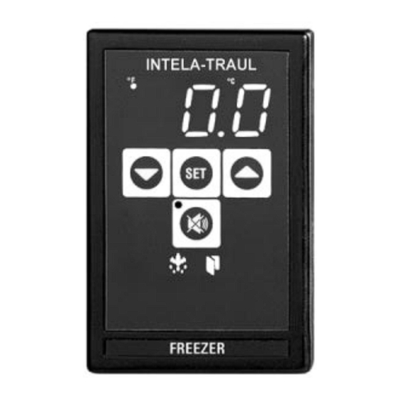
INTELA-TRAUL
MASTER SERVICE MANUAL
For All Full Size Undercounter, G-Series and
R&A Series Refrigerator, Freezer, Dual-Temp
and Hot Food Unit Controllers
Traulsen
4401 Blue Mound Road - Fort Worth, Texas 76106
Phone: (800) 825-8220 or (817) 625-9671
Fax-Service (817) 740-6757
Form Number TR35705, revised 10/04
Advertisement
Table of Contents
Troubleshooting

Summary of Contents for Traulsen INTELA-TRAUL
- Page 1 Quality Refrigeration ® INTELA-TRAUL MASTER SERVICE MANUAL For All Full Size Undercounter, G-Series and R&A Series Refrigerator, Freezer, Dual-Temp and Hot Food Unit Controllers Traulsen 4401 Blue Mound Road - Fort Worth, Texas 76106 Phone: (800) 825-8220 or (817) 625-9671...
-
Page 2: Table Of Contents
TABLE OF CONTENTS I. General Information a) How To Use This Manual Page 2 b) About INTELA-TRAUL Page 2 c) Operating The Controller Page 2 II. Basic Service Procedures a) Adjusting The Temperature Page 3 b) Starting A Manual Defrost Cycle (R & A Series) -
Page 3: General Information
These microprocessor controls both monitor a cabinet air sensor and a coil sensor. The INTELA-TRAUL on the R & A Series also includes a discharge line sensor and a relative humidity sensor (H1 versions only). In conjuction with the... -
Page 4: Basic Service Procedures
II. BASIC SERVICE PROCEDURES The Display II. a - ADJUSTING THE TEMPERATURE: Will Read Step 1: Press . Display will read “CUS.” Step 2: Press . Display will read “000” with the left digit flashing. Step 3: Press . Display will read “000” with the center digit flashing. Step 4: Press until the center digit changes to an “A”. -
Page 5: B) Starting A Manual Defrost Cycle (R & A Series)
NOTE: The controller will automatically revert back to normal operation after a delay of approximately 20-30 seconds. NOTE: Traulsen R & A Series refrigerator models also include an off- cycle defrost feature, which occurs once an hour. This is indicated by the control display, is time or temperature... -
Page 6: C) Starting A Manual Defrost Cycle (G-Series)
This is indicated by the control display, is time terminated, and is generally of 3 - 10 minutes in duration. The defrost cycle on Traulsen G-Series freezer models can be either time or temperature terminated. -
Page 7: Troubleshooting
III. TROUBLESHOOTING The Display III. a - CHECKING FOR DEFECTIVE SENSORS: Will Read Step 1: Press . Display will read “CUS.” Step 2: Press . Display will read “000” with the left digit flashing. Step 3: Press . Display will read “000” with the center digit flashing. Step 4: Press until the center digit changes to an “A”. -
Page 8: B) Checking For Failed Relays
III. TROUBLESHOOTING III. b - CHECKING FOR FAILED RELAYS: Checking For A Failed Internal Controller Relay: 1. Gain access to Controller compressor relay (see REMOVAL INSTRUCTIONS within this service manual for the specific type of controller your are servicing). 2. Locate the connector with the black/blue/purple wires and unplug it. Refer to the schematic on the side of the controller, or refer to the appropriate wiring diagram (to obtain this please contact the factory, referencing the serial numberof the unit involved). -
Page 9: C) Checking For Other Failed Components
III. TROUBLESHOOTING III. c - CHECKING FOR OTHER FAILED COMPONENTS: Checking For A Failed Door Switch: 1. Remove the door(s) from the unit involved. 2. Locate the door switch, which is located behind the top door hinge(s). 3. Remove the switch from the cabinet. 4. -
Page 10: D) Checking For Iced Evaporator Coil
III. TROUBLESHOOTING III. d - CHECKING FOR ICED EVAPORATOR COIL: With evaporator Check evaporator NOT OK Replace clear of ice is blower motor for evaporator there proper proper operation. blower motor. air-flow? Check DEF settings in Reset Evap’r controller parameters. NOT OK control or ducting... -
Page 11: E) Proper Sensor Placement
III. TROUBLESHOOTING III. e - PROPER SENSOR PLACEMENT: Coil Sensor: Correct Sensor The coil sensor should be inserted into Location the return air side of the evaporator coil. On freezer models only this sensor should be centered approximately 2” (two inches) from the top (horizontally through coil - centered in coil). -
Page 12: Control Architecture
IV. CONTROL ARCHITECTURE IV. a - R & A SERIES REFRIGERATOR & FREEZER VERTICAL CONTROLLER: NOTES: IRDA not included on equipment manufactured with the MIT II control version. See parts assembly on pages 12-13. -11-... - Page 13 IV. CONTROL ARCHITECTURE HOLDER CLIP P/N 337-60038-00 H1 CONTROLLER DEFROST COMPRESSOR RELAY POWER LINE IN 2 DOOR RELAY EVAP BLOWER RELAY POWER LINE IN 1 TRANSFORMER/ RS485 HORN DISCHARGE LINE DOOR RELAY CABINET RH/AMBIENT EVAP HOLDER CLIP 1= Set of two (can be ordered separately). COIL P/N 337-60038-00 2= Requires unit model number and serial...
- Page 14 IV. CONTROL ARCHITECTURE IV. b - R & A SERIES REFRIGERATOR & FREEZER VERTICAL CONTROLLER: Parts assembly for H1 thru MIT control versions only CABINET SENSOR - 337-60069-02 COIL SENSOR - 337-60071-02 DISCHARGE SENSOR - 337-60072-00 TO TRANSFORMER (not included for MIT II versions) HOLDER CLIP CONTROL CABLE 337-60038-00...
- Page 15 IV. CONTROL ARCHITECTURE IV. c - UC & UL (UNDERCOUNTER) HORIZONTAL CONTROLLER: DEFROST COMPRESSOR 1= Set of two (can be ordered separately). 2= Requires unit model number and serial RELAY POWER LINE IN 2 number to place order. DOOR HEATER EVAP HOLDER CLIP BLOWER RELAY P/N 337-60038-00...
-
Page 16: B) Undercounter Refrigerator & Freezer Horizontal Controllers
IV. CONTROL ARCHITECTURE IV. c - UC & UL (UNDERCOUNTER) HORIZONTAL CONTROLLER: Parts assembly for MIT control version only CABINET SENSOR - 337-60069-02 COIL SENSOR - 337-60071-02 DISCHARGE SENSOR - 337-60072-00 TO TRANSFORMER (not included for MIT II versions) HOLDER CLIP CONTROL CABLE 337-60038-00 333-60228-00... -
Page 17: C) G-Series Refrigerator & Freezer Vertical Controllers
IV. CONTROL ARCHITECTURE IV. d - G-SERIES REFRIGERATOR & FREEZER VERTICAL CONTROLLER: -16-... - Page 18 IV. CONTROL ARCHITECTURE IV. d - G-SERIES REFRIGERATOR & FREEZER VERTICAL CONTROLLER: -17-...
-
Page 19: D) R & A Series Heated Cabinet Vertical Controllers
IV. CONTROL ARCHITECTURE IV. e - R-SERIES HEATED CABINET VERTICAL CONTROLLER: NOTES: IRDA not included on equipment manufactured with MIT II control version. See parts assembly on pages 17-18. HOT FOOD CABINET START-UP (pre-MIT version): When power is first applied to the unit, you must set the temperature by pressing the “SET”... - Page 20 IV. CONTROL ARCHITECTURE IV. e - R-SERIES HEATED CABINET VERTICAL CONTROLLER: Parts assembly for H1 control versions only 1= Set of two (can be ordered separately). 2= Requires unit model number and serial number to place order. HORN 337-60070-00 -19-...
- Page 21 IV. CONTROL ARCHITECTURE IV. e - R-SERIES HEATED CABINET VERTICAL CONTROLLER: Parts assembly for MIT control versions only CABINET SENSOR - 337-60069-02 UNUSED UNUSED TO TRANSFORMER (not included for MIT II versions) HOLDER CLIP CONTROL CABLE 337-60038-00 333-60228-00 (set of two) RELAY BOX 337-60171-02 HORN...
-
Page 22: Removal/Installation
V. REMOVAL/INSTALLATION V. a - ALL VERTICAL CONTROLLERS: To remove INTELA-TRAUL ® (p/n’s 337-60090-00, 337-60091-00 and 337-60092-00) and G-Series (p/n’s 337-60093-00, 337-60094-00 and 337-60095-00) Vertical Controller from the unit in which it is installed, proceed as follows (If unable to access the unit from the rear perform steps 1 through 3, otherwise, proceed to step 4): 1. - Page 23 V. REMOVAL/INSTALLATION WARNING: DISCONNECT ALL POWER BEFORE PROCEEDING 4. At the top of the junction box, JUNCTION (3) PHILLIPS remove three (3) Phillips head HEAD SCREWS screws. Set screws aside. 5. Locate one (1) Phillips head screw at bottom of junction box, and remove.
-
Page 24: B) All Horizontal Controllers
V. REMOVAL/INSTALLATION V. a - ALL HORIZONTAL CONTROLLERS: ® To remove INTELA-TRAUL (p/n’s 337-60096-00 and 337-60097-00) Horizontal Controller from the unit in which it is installed, proceed as follows: WARNING: DISCONNECT ALL POWER BEFORE PROCEEDING 1. Check to make sure that the... -
Page 25: Problem Diagnosis
VI. PROBLEM DIAGNOSIS VI. a - HOW TO USE THE TROUBLESHOOTING TREES: The troubleshooting trees on the following pages were developed as an aid to the service technician in determining the exact solution to a certain problem or mal- function. When used as designed, the troubleshooting trees can lead you from a general symptom to the most likely component to suspect as the cause of the problem. -
Page 26: B) Hi-Temp Alarm (All Ht/Ri & Lt/If Models)
VI. b- HIGH TEMPERATURE ALARM Door(s) open longer than 5 Close minutes? door(s). Excessive amount of hot Reduce product placed volume of in unit? hot product. Is evaporator Defrost coil frozen up? evaporator coil. IS NOT OK Check compressor refrigerant. for low refrigerant. -
Page 27: C) Lo-Temp Alarm (All Ht/Ri & Lt/If Models)
VI. c- LOW TEMPERATURE ALARM Is temperature setting for unit Increase too low? operating temperature. Is there food product in the product unit? to the unit. Check for failed Replace IS NOT OK compressor relay. failed controller or slave relay. IS OK Check that sensor IS NOT OK... -
Page 28: D) Door Open Alarm (All Ht/Ri, Lt/If Hf/Ih Models)
VI. d- DOOR OPEN ALARM Door(s) open Close longer than 5 door(s). minutes? IS NOT OK Replace Checkfor a failed door/ failed light relay. relay. IS OK Is there water Replace in the door door switch? switch. IS NOT OK Replace Check for mis-wired door... -
Page 29: E) Power Loss Alarm (All Ht/Ri, Lt/If Hf/Ih Models)
VI. e- POWER LOSS ALARM Is unit Plug plugged unit in. Has unit Full suffered a loss operation of power due to will return bad weather? when service is restored. Is unit receiving low Contact voltage input? local utility provider. IS NOT OK Replace Check for failed... -
Page 30: F) System Leak Alarm (All Ht/Ri & Lt/If Models)
VI. f- SYSTEM LEAK ALARM Does discharge temp rise 45°F within 5 min. of a ref’n. cycle start? IS NOT OK Check compressor for low refrigerant. refrigerant. IS OK IS NOT OK Check discharge Replace line sensor. failed sensor. Are sensor probes properly Connect connected? -
Page 31: G) Condenserclean Alarm (All Ht/Ri & Lt/If Models)
VI. g - CONDENSERCLEAN ALARM condenser Clean coil dirty? condenser coil. condenser fan Properly disconnected? conenct fan. IS NOT OK Check forfailed condenser fan. Replace fan. Are there any obstructions Remove at top or rear obstructions. of unit? Is the room Lower temperature the room... -
Page 32: Accessing The Engineering Level
VII. ACCESSING THE ENGINEERING LEVEL VII. a - ACCESSING THE ENGINEERING LEVEL: Not all control parameters can be adjusted at the customers level of access. To adjust these other parameters it is first necessary to gain access to the ENGINEERING LEVEL. Please follow the below procedure in order to enter this level. -
Page 33: Control Parameters
VIII. CONTROL PARAMETERS VIII. a - PARAMETER DESCRIPTIONS: 3-digit code which identifies the .hex file loaded at the factory. Device address for NAFEM networks. Communications rate when connected into a NAFEM network. Allow the control to communicate with a NAFEM network. High value of desired cabinet temperature range. - Page 34 VIII. CONTROL PARAMETERS VIII. a - PARAMETER DESCRIPTIONS (continued): The amount of time, in seconds, that a visual alarm text will be displayed. Alarm temperature delay. Allows the customer to set the type of audible alarm style, either Blast, OFF or Continuous.
-
Page 35: B) Parameter Access & Units Of Measurement
VIII. CONTROL PARAMETERS VIII. b - PARAMETER ACCCESS & UNITS OF MEASUREMENT: H1, MIT I & MIT II CONTROL VERSIONS ONLY Control Unit of Parameter Description Access Measure ADR* Device Address BAU* Comm. Baud Rate in K KBaud NAF* NAFEM Communications Enable On/Off Temperature Set-Point High Degree... -
Page 36: C) G-Series Parameter Settings
VIII. CONTROL PARAMETERS VIII. c - G-SERIES PARAMETER SETTINGS (MIT II Control Version): Control Freezer Models Refrigerator Models Parameter GF1 ADR* BAU* NAF* -5.2 38.1 39.2 39.2 26.1 -3.1 -3.1 30.2 39.2 39.2 -5.2 -6.2 -6.2 26.1 35.2 -18.4 -10 30.2 30.2 30.2... -
Page 37: D) R-Series Parameter Settings - Refrigerator Models
VIII. CONTROL PARAMETERS VIII. d - R-SERIES PARAMETER SETTINGS (MIT II Control Version): Control Refrigerator Models Parameter RA1 39.2 39.2 39.2 39.2 38.1 38.1 39.2 39.2 39.2 39.2 39.2 39.2 39.2 39.2 30.2 30.2 30.2 30.2 30.2 30.2 30.2 30.2 45.1 45.1 45.1... -
Page 38: E) R-Series Parameter Settings - Freezer Models
VIII. CONTROL PARAMETERS VIII. e - R-SERIES PARAMETER SETTINGS (MIT II Control Version): Control Freezer Models Parameter RF1 -15.4 -10 -5.2 -20.2 -15.4 -15.4 -13.6 -2.2 -2.2 -5.2 -20.2 -20.2 -6.2 -6.2 -15.4 -25.6 -25.6 -17.8 Starts a new defrost cycle at any time or stops a current defrost cycle. 220.1 220.1 220.1 220.1 220.1 Set the hours and minutes in military time. -
Page 39: F) Undercounter Parameter Settings
VIII. CONTROL PARAMETERS VIII. f - UNDERCOUNTER PARAMETER SETTINGS (MIT II Control Version): Control Parameter UF1 38.1 38.1 38.1 33.8 33.8 33.8 -0.31 36 -6.2 30.2 30.2 30.2 GAS GAS 45.1 45.1 Starts a new defrost cycle at any time or stops a current defrost cycle. 220.1 220.1 220.1 Set the hours and minutes in military time. - Page 40 HOURS OF OPERATION: Monday thru Friday 7:30 am - 4:30 pm CST Traulsen 4401 Blue Mound Road Fort Worth, TX 76106 Phone: (800) 825-8220 Fax-Svce: (817) 740-6757 Quality Refrigeration Website: www.traulsen.com...
Need help?
Do you have a question about the INTELA-TRAUL and is the answer not in the manual?
Questions and answers