Advertisement
Table of Contents
- 1 Table of Contents
- 2 Safety Considerations
- 3 Introduction
- 4 Operation
- 5 Removing the Existing Motor from Pump
- 6 Topside Interface Overview
- 7 Single Speed Connection with Timer
- 8 Two Speed Connections with Timer
- 9 Automation Controller Signal Line Connection
- 10 Automatic Reduced Speed Selection
- 11 Software Error Code Matrix
- 12 Troubleshooting Guide
- Download this manual
Advertisement
Table of Contents

Summary of Contents for imPower RB003
- Page 1 Installation Guide www.imPowerDealer.com...
- Page 2 Marathon Electric offers a full line of motors for the pool, spa and bath markets. Poolside contractors prefer our pool and spa motors for their quick installation, long life and easy serviceability. Marathon designs motors for a variety of pool and spa applications, including above-ground pool, in-ground pool, commercial pool, variable-speed, heat pumps and all other standard applications.
-
Page 3: Table Of Contents
Table of Contents Safety Considerations Introduction Operation Removing the Existing Motor from Pump Topside Interface Overview Single Speed Connection with Timer Two Speed Connections with Timer Automation Controller Signal Line Connection Automatic Reduced Speed Selection Software Error Code Matrix Troubleshooting Guide Please read the entire instruction manual before starting the installation. -
Page 4: Safety Considerations
Evergreen IM motor and in this manual. Please read and observe all Evergreen IM motor and in this manual. Please read and observe all of these safety concerns. The following definitions are used as safety considerations on the imPower motor of these safety concerns. of these safety concerns. - Page 5 Evergreen IM motor and in this manual. Please read and observe all Evergreen IM motor and in this manual. Please read and observe all The following definitions are used as safety considerations on the imPower motor Installation and service of this motor should be attempted only by of these safety concerns.
-
Page 6: Introduction
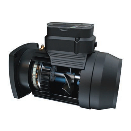
The PMAC machine is inherently more efficiency than its induction counterpart, resulting in energy consumption savings of up to 85%. This imPower motor is designed to safely replace existing full-rated pool filter pump motors rated at 3/4 HP 1.65SF or up-rated motors at 1.0HP 1.25SF. This motor also features three selectable speeds either through the use of the patent pending auto speed switch feature, top panel push buttons, external multi-speed timers, or through external automation controls. -
Page 7: Operation
This is critical to its effectiveness with all existing line-power cutoff timers and automation controllers. -
Page 8: Removing The Existing Motor From Pump
Step 4: To remove the impeller lock the shaft by placing a wrench or a flathead screwdriver at the opening in the rear. Note: Do not reuse the seal from the existing motor when installing the imPower motor. Remove the screws holding the seal plate onto the motor. Step 5: Remove the pump motor by removing the four bolts holding the motor to the seal plate of the pump. -
Page 9: Topside Interface Overview
Topside Interface Overview The topside interface on the imPower motor provides functionality to change amongst three distinct preset speeds via either a button press or by a remote timer / automation controller. Green display LED’s will light to indicate the currently selected speed as well as to indicate power is applied to the motor. -
Page 10: Single Speed Connection With Timer
Always disconnect the main power from the unit prior to servicing the pool pump filter motor. It is also good practice to confirm the power is off with a voltage meter These steps as outlined below are for connection of the imPower motor to a single speed timer. Step 1: Remove the three screws holding the top control enclosure onto the motor. - Page 11 Step 7: Carefully fold the extra wires inside the terminal box and place the top control panel back on top of the terminal box. Step 8: Tighten the three screws into the terminal box while applying light pressure to the top control enclosure. Step 9: Replace and tighten the screws to mount the seal plate onto the motor.
- Page 12 The standard operation identified in Note 1 can be resumed if the power is turned off at the timer and turned back on. Extended Functionality The imPower motor also has the ability to operate on high speed for only the mandatory two-minute pump priming cycle before changing to low speed until power is removed.
-
Page 13: Two Speed Connections With Timer
Installation and service of this motor should be attempted only by trained service technicians familiar with the Evergreen instructions and training manual. This motor should be installed in accordance with accepted practices and installation instructions, and in compliance with all national and local codes. - Page 14 Step 5: Remove the three screws holding the top control enclosure onto the motor. Carefully lift the top panel and turn it over to expose the inside of the terminal box. Step Run the High Speed Black, Low Speed Red, L2, and Ground wires from the conduit cable through the opening on the right side of the motor. Step 7: Connect the wire for Circuit 1 from the timer to the opening directly across from the BLACK wire on the terminal block (refer to Figure 10).
- Page 15 Step 16: Replace the impeller. Make sure that the impeller can spin freely in the housing. Step 17: Replace the diffuser. Step 18: Replace and tighten the bolts that retain the motor/seal plate assembly to the pump. Step 19: Connect the appropriately sized ground conductor to the supplied grounding/bonding lug.
-
Page 16: Automation Controller Signal Line Connection
Always disconnect the main power from the unit prior to servicing the pool pump filter motor. It is also good practice to confirm the power is off with a voltage meter. The steps as outlined below are for connection of the imPower motor to an auto- mation controller. The optional low voltage cable connection kit P/N 391-200-01 (15’ cord) or P/N 391-200-02 (25’ cord) will be required. - Page 17 Figure 13 Figure 14 Step Plug the connector end of the low voltage cable (P/N 391-200-01 or P/N 391-200-02) into the connector on the underside of the top control enclosure as seen in Figure 13. Step 10: Carefully fold the extra wires inside the terminal box and place the top control panel back on top of the terminal box and tighten the three topside enclosure screws. Step 11: Carefully pull the low voltage cable to reduce the amount of excess cable inside the connection box.
- Page 18 Step 13: Wire the low voltage cable to the automation controller. The speed connections and their corresponding lead colors are shown in Figure 17. The (+) marking denotes the positive side controller connection and the (-) denotes the negative side controller connection. High Speed: BLACK (+) WHITE (-) Medium Speed: BROWN (+) BLUE (-) Low Speed:...
- Page 19 Notes: The automation controller allows for the programmable operation of all three speeds. The motor will start on high speed for each speed selection and operate through its two-minute prime cycle before reacting to any controller inputs. The on time and speeds should be set so that the pool can meet the total number of turns as required by local/ state regulations.
-
Page 20: Automatic Reduced Speed Selection
Automatic Reduced Speed Selection The imPower motor has been programmed with a feature called the Automatic Reduced Speed Selection function that allows for the maximum energy savings via multi-speed operation despite using a standard single-speed timer. This feature also applies to a multi-speed timer where the Circuit 2 speed can either be assigned to medium or low speed. - Page 21 Default Reduced Speed Operation: 1. For a standard single speed timer connection, the motor will run high speed for the duration of the two hour initial operation. After this time period, the speed will convert to the new default speed. 2. For a modified single speed timer connection, the motor will run high speed for the duration of the two-minute initial operation. After this time period, the speed will convert to the new default speed.
-
Page 22: Software Error Code Matrix
Software Error Code Matrix The imPower control panel has a red error display LED to indicate operation issues. Normal operation is indicated by a single flash of this LED upon startup. Any subsequent blink sequence of this LED indicates that a fault has been registered by the motor control, with the explanation of these faults given in the below table. - Page 23 Blinks Faults Software Cause Action Output shaft Motor failed to start. - Manually rotate the shaft seized Motor was stopped. via the shaft access in the fan cover - Inspect all equipment in-line with the pump for obstructions or locked pump parts.
-
Page 24: Troubleshooting Guide
Action: Assuming this issue was not pre-existing, the programmed low speed on the imPower likely does not provide sufficient flow / pressure to pump the water up to the solar heating units. Change the speed to medium and determine if this solves the issue. If it does, change the default reduced... - Page 25 Action: Assuming this issue was not pre-existing, the programmed low speed on the imPower likely does not provide sufficient flow / pressure to de- velop the necessary suction / pressure required of the pool cleaner. Change the speed to medium and determine if this solves the issue. If it does not, change the speed to high.
- Page 26 Notes:...
- Page 27 Notes:...
- Page 28 Need Additional imPower Help? Contractor Hotline: 800-683-9144 imPower Website: www.imPowerDealer.com Rev 1.4 06/11 A Regal Beloit Company 7032M/06-11/BH...
Need help?
Do you have a question about the RB003 and is the answer not in the manual?
Questions and answers