
Subscribe to Our Youtube Channel
Related Manuals for AirPlus KRT2

Summary of Contents for AirPlus KRT2
- Page 1 User & Installation manual Doc.-Nr: DE-3000-800100e VHF- Communication Transceiver Revision 5.0 KRT2 & KRT 2A Software >5.00 KRT2 VHF Communication Transceiver P/N 100-( )-( ) Operation and Installation Manual - 1 - of 46...
- Page 2 Doc.-Nr: User & Installation manual DE-3000-800100e VHF- Communication Transceiver Revision 5.0 KRT2 & KRT 2A Software >5.00 Record of Revisions Revision Date Subject 06 Juni 2010 Erstausgabe 20 Sep 2010 Revision Stecker / Redaktionelle Änderungen 05 Feb 2011 Editorial update...
-
Page 3: Table Of Contents
GENERAL ........................... 5 1.1. Symbols ..........................5 1.2. Abbreviations........................6 1.3. Customer Service ......................7 1.4. KRT2 Transceiver properties ................... 7 CONTROL general ......................8 2.1. Control Elements Overview ..................... 8 2.2. Display ..........................10 OPERATION ........................12 3.1. General ..........................12 3.2. - Page 4 User & Installation manual Doc.-Nr: DE-3000-800100e VHF- Communication Transceiver Revision 5.0 KRT2 & KRT 2A Software >5.00 5.6.3. External Audio Input ....................31 5.7. Finally Audio-Setup ....................... 32 5.7.1. For gliders ....................... 32 5.7.2. For motor gliders ..................... 32 5.7.3.
-
Page 5: General
Software >5.00 GENERAL This manual contains information about the physical, mechanical and electrical properties as well as a description for the operation and installation of the VHF airborne transceiver KRT2. 1.1. Symbols WARNING Non compliance may cause personnel injury due to radiation or fire. -
Page 6: Abbreviations
User & Installation manual Doc.-Nr: DE-3000-800100e VHF- Communication Transceiver Revision 5.0 KRT2 & KRT 2A Software >5.00 1.2. Abbreviations Abb Description Definition PTT Push to Talk Transmitter activation VOX Voice operated intercom Voice level setting fort he activation of the intercom... -
Page 7: Customer Service
1.3. Customer Service In order to process returned units most expeditiously, please fill in the form xxxxxxxxxxxxxxxxxxx to be found under AIRplus Service at www.airplus24.com. Suggestions which will improve this manual are very much appreciated at: www.airplus24.com Information concerning software updates are available under AIRplus Avionics at www.airplus24.com... -
Page 8: Control General
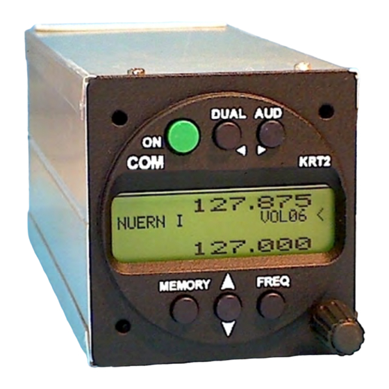
Doc.-Nr: User & Installation manual DE-3000-800100e VHF- Communication Transceiver Revision 5.0 KRT2 & KRT 2A Software >5.00 CONTROL general 2.1. Control Elements Overview 8 of 46... - Page 9 Doc.-Nr: User & Installation manual DE-3000-800100e VHF- Communication Transceiver Revision 5.0 KRT2 & KRT 2A Software >5.00 ON / OFF Self-locking switch 1. Scanning between the Active and Standby frequencies DUAL 2. Positioning cursor to the left when WATCH programming the station designator 1.
-
Page 10: Display
Doc.-Nr: User & Installation manual DE-3000-800100e VHF- Communication Transceiver Revision 5.0 KRT2 & KRT 2A Software >5.00 2.2. Display Indication Meaning Remarks Reception RX is displayed during reception with a squelch value of 02 or more Transmission Transmitter operates normally... -
Page 11: Menu Functions
Doc.-Nr: User & Installation manual DE-3000-800100e VHF- Communication Transceiver Revision 5.0 KRT2 & KRT 2A Software >5.00 Display Meaning Remark DUAL Active frequency AND DUAL function is deactivated by frequency Standby Frequency are change or by pressing the monitored simultaneously... -
Page 12: Operation
Doc.-Nr: User & Installation manual DE-3000-800100e VHF- Communication Transceiver Revision 5.0 KRT2 & KRT 2A Software >5.00 OPERATION 3.1. General There is a normal operating mode in which the turning knob always is connected to the volume (VOL). The normal operating mode can be left by pressing the AUD, FREQ or MEMORY button. -
Page 13: Direct Frequency Selection
User & Installation manual Doc.-Nr: DE-3000-800100e VHF- Communication Transceiver Revision 5.0 KRT2 & KRT 2A Software >5.00 • Selection from the favourite list (index 0-99) 3.3.1. Direct Frequency Selection The Standby-Frequency is set with the tuning knob in 3 different ranges. The selected range is highlighted and can be changed with the FREQ button. -
Page 14: Storing And Editing Favourites
Doc.-Nr: DE-3000-800100e VHF- Communication Transceiver Revision 5.0 KRT2 & KRT 2A Software >5.00 Exchanges the Active and Standby frequencies. The selection procedure can be terminated with either the AUD or FREQ buttons. Without pressing any of these buttons the unit will return to its normal operating mode after 20 seconds. - Page 15 Doc.-Nr: DE-3000-800100e VHF- Communication Transceiver Revision 5.0 KRT2 & KRT 2A Software >5.00 for editing he designator if required Pressing MEMORY again terminates editing and SAVE? will show up. SAVE? is available for 20 seconds and must be acknowledged by the button.
-
Page 16: Aud - Audio Menu
Doc.-Nr: User & Installation manual DE-3000-800100e VHF- Communication Transceiver Revision 5.0 KRT2 & KRT 2A Software >5.00 3.4. AUD – Audio Menu Any action in the Audio Menu requires the pointer (<) to be next to the Audio menu window (see picture). -
Page 17: Vox - Intercom Voice Trigger Level Setting
User & Installation manual DE-3000-800100e VHF- Communication Transceiver Revision 5.0 KRT2 & KRT 2A Software >5.00 The Squelch setting is depending on several factors. For engine driven airplanes an initial setting of 05-08 is recommended. Gliders may need a lower setting. The lower the Squelch level value the higher is the input sensitivity. -
Page 18: Int - Intercom Volume
Doc.-Nr: User & Installation manual DE-3000-800100e VHF- Communication Transceiver Revision 5.0 KRT2 & KRT 2A Software >5.00 3.4.5. – Intercom Volume Pressing the AUD button four times enables the turning knob to set the intercom volume. Range: 01 - 10 INTnn 3.4.6. -
Page 19: Mic - Setup
Doc.-Nr: User & Installation manual DE-3000-800100e VHF- Communication Transceiver Revision 5.0 KRT2 & KRT 2A Software >5.00 3.4.10. MIC – Setup Each of the two microphone inputs channels can be configured individually, which enables different microphone types to be used. - Page 20 User & Installation manual DE-3000-800100e VHF- Communication Transceiver Revision 5.0 KRT2 & KRT 2A Software >5.00 MIC levels 10 and 11 are special settings for low microphone levels like dynamic micro-phones often used in gliders. 10 is used for non-amplified Electret microphones with a 8 volt supply voltage.
-
Page 21: Dual Watch
Software >5.00 DUAL 3.5. Watch Because the communication transceiver KRT2 contains only one receiver, DUAL watch is achieved by alternating between the Active and Standby frequencies. The DUAL button activates and deactivates the dual watch function. Deactivation also can take place by pressing either the FREQ or MEMORY buttons. - Page 22 Doc.-Nr: User & Installation manual DE-3000-800100e VHF- Communication Transceiver Revision 5.0 KRT2 & KRT 2A Software >5.00 Standby and Active frequencies can be exchanged when in the DUAL mode. The transmitter operates on the Active frequency only. Summary: Select the Standby frequency to be watched additionally.
-
Page 23: Transmitter Operation
Doc.-Nr: User & Installation manual DE-3000-800100e VHF- Communication Transceiver Revision 5.0 KRT2 & KRT 2A Software >5.00 3.6. Transmitter Operation The unit transmits on the active frequency (upper line) as long as a PTT (press to talk) switch is pressed. -
Page 24: Self Test Monitor
Doc.-Nr: User & Installation manual DE-3000-800100e VHF- Communication Transceiver Revision 5.0 KRT2 & KRT 2A Software >5.00 3.7. Self test monitor There is a permanent back ground test system active. The field for battery status & error (see Control Elements Overview) is used to indicate warnings and in case of hardware failure, different error reports. -
Page 25: Resetting To Factory Settings
Doc.-Nr: User & Installation manual DE-3000-800100e VHF- Communication Transceiver Revision 5.0 KRT2 & KRT 2A Software >5.00 3.8. Resetting to factory settings Returning to the factory settings can only be initiated during power-up. During power-up the MEMORY and DUAL buttons must be pressed simultaneously and the display will show “SET DEFAULTS”. -
Page 26: Set Up - Menu
Doc.-Nr: User & Installation manual DE-3000-800100e VHF- Communication Transceiver Revision 5.0 KRT2 & KRT 2A Software >5.00 3.9. SET UP - Menu During power-up the MEMORY buttons must be pressed There are two functions within the Set-up menu: • ERASE – Erasing of the favourites (frequency and designator) •... -
Page 27: Channel Spacing
The error message disappears when a valid command or a new frequency has been input, latest however after 5 seconds. Remote control unit errors do not interfere with the KRT2 transceiver operation. Data transmissions between the transceiver KRT2 and the remote control unit is checked once every minute. -
Page 28: Installation
5.3. Scope of delivery Part Number Description KRT2 KRT2 - VHF Transceiver ZUB2 (3 pcs) Mounting screw KRT2 - for panels up to SSKRT2 Connector (when no cable set was ordered) …………………… Operation and Installation Manual EASA Form 1 28 of 46... -
Page 29: Unpacking And Inspecting The Equipment
Doc.-Nr: User & Installation manual DE-3000-800100e VHF- Communication Transceiver Revision 5.0 KRT2 & KRT 2A Software >5.00 5.4. Unpacking and Inspecting the Equipment Carefully unpack the equipment. Damages due to transportation must immediately be reported to the shipping company. Save the shipping container and all packing material to substantiate your claim. -
Page 30: Electrical Connections
Motor gliders should have a toggle switch installed to differentiate between motor less flight with dynamic microphones and powered flight with headsets. When the AUTO mode is selected in the MIC-Setup menu the KRT2 automatically recognizes to which microphone type has been switched and acts accordingly. -
Page 31: Earphone Connection
Doc.-Nr: User & Installation manual DE-3000-800100e VHF- Communication Transceiver Revision 5.0 KRT2 & KRT 2A Software >5.00 Because the 8V supply voltage is switched off when dynamic microphones are used during glider flight the second (copilot) headset microphone is disabled. -
Page 32: Finally Audio-Setup
Doc.-Nr: User & Installation manual DE-3000-800100e VHF- Communication Transceiver Revision 5.0 KRT2 & KRT 2A Software >5.00 5.7. Finally Audio-Setup This is an overview for a correct audio set up depending on the usage. 5.7.1. For gliders Press button AUD 3x for VOX: Set to VOX 10 (turn off). -
Page 33: Wiring
Doc.-Nr: User & Installation manual DE-3000-800100e VHF- Communication Transceiver Revision 5.0 KRT2 & KRT 2A Software >5.00 5.8. Wiring 5.8.1. Wire Gauges Supply lines (Power, GND): AWG18 (0,96 mm²) Control lines: AWG22 (0,38 mm²) All wires must be aviation certified. -
Page 34: Wiring Diagram
Doc.-Nr: User & Installation manual DE-3000-800100e VHF- Communication Transceiver Revision 5.0 KRT2 & KRT 2A Software >5.00 5.8.3. Wiring Diagram 34 of 46... - Page 35 Doc.-Nr: User & Installation manual DE-3000-800100e VHF- Communication Transceiver Revision 5.0 KRT2 & KRT 2A Software >5.00 35 of 46...
-
Page 36: Connection Support
Doc.-Nr: User & Installation manual DE-3000-800100e VHF- Communication Transceiver Revision 5.0 KRT2 & KRT 2A Software >5.00 5.8.4. Connection support In order to connect shields of all cables at a single point and to avoid ground loops an adapter board as shown is recommended. -
Page 37: Antenna
Doc.-Nr: User & Installation manual DE-3000-800100e VHF- Communication Transceiver Revision 5.0 KRT2 & KRT 2A Software >5.00 5.9. Antenna 5.9.1. Antenna Selection • A 50 Ohms impedance VHF-COM-antenna is required. • The antenna must be approved in respect to aircraft type and installation location. -
Page 38: Microphone General
Communication with the VOX system requires pin 12 to be connected to GND by means of one or two intercom switches. The KRT2 unit transmits only when a PTT switch is pressed. Cockpit noise suppression is only possible with differential microphones used in modern headsets. -
Page 39: Starting Up
User & Installation manual DE-3000-800100e VHF- Communication Transceiver Revision 5.0 KRT2 & KRT 2A Software >5.00 A test flight is recommended to verify proper transceiver operation. The following items should be checked: • Check transceiver operation with a radio station at least 50 km away when at 2000ft or above. - Page 40 Doc.-Nr: User & Installation manual DE-3000-800100e VHF- Communication Transceiver Revision 5.0 KRT2 & KRT 2A Software >5.00 40 of 46...
-
Page 41: Drawings
Doc.-Nr: User & Installation manual DE-3000-800100e VHF- Communication Transceiver Revision 5.0 KRT2 & KRT 2A Software >5.00 5.14. Drawings 5.14.1. Dimensions 41 of 46... -
Page 42: Installation Directions
Doc.-Nr: User & Installation manual DE-3000-800100e VHF- Communication Transceiver Revision 5.0 KRT2 & KRT 2A Software >5.00 5.14.2. Installation Directions Connection Area Panel Cut-out 42 of 46... -
Page 43: Annex
Doc.-Nr: User & Installation manual DE-3000-800100e VHF- Communication Transceiver Revision 5.0 KRT2 & KRT 2A Software >5.00 ANNEX 6.1. Frequency / Channel- schedule The following table contains the operating and displayed frequencies between 118.000 and... 118.100 MHz. The table can be continued up to 136.975 MHz following the same principle. -
Page 44: Technical Data
Doc.-Nr: User & Installation manual DE-3000-800100e VHF- Communication Transceiver Revision 5.0 KRT2 & KRT 2A Software >5.00 6.2. Technical Data GENERAL ETSO-2C169a, ED-23B Class 4 Compliance ED-23B Class C Standards TSO-C169a,Class 6 TSO-C169a, Class H1 & H2 EUROCAE ED-23B Standards... - Page 45 Doc.-Nr: User & Installation manual DE-3000-800100e VHF- Communication Transceiver Revision 5.0 KRT2 & KRT 2A Software >5.00 TRANSMITTER POWER OUTPUT 6 W (nominal) 4 W (minimal) HARMONIC DISTORTION <10 % at 70 % modulation SIDETONE OUTPUT >0,5W an 300 (head set output) MICROPHONE INPUTS 2 x standard (50mV…2V) into 100...
- Page 46 Doc.-Nr: User & Installation manual DE-3000-800100e VHF- Communication Transceiver Revision 5.0 KRT2 & KRT 2A Software >5.00 46 of 46...
Need help?
Do you have a question about the KRT2 and is the answer not in the manual?
Questions and answers