Advertisement
Mart Cart
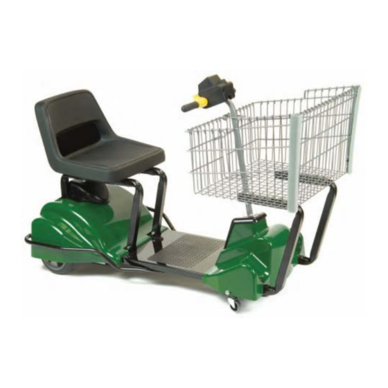
Model 3563
Technical Overview
This document is a technical overview of the Mart Cart model 3563. Its
purpose is to describe the major components of units that are currently being
produced. Some components may be updated from previous versions of this
model. Some optional components may not be discussed in this document.
For more detailed information, please contact our Service Department at
800-548-3373 or email techservice@assembledproducts.com.
Go to the Table of Contents
Advertisement
Table of Contents

Related Manuals for Mart Cart 3563


Summary of Contents for Mart Cart 3563
- Page 1 Model 3563 Technical Overview This document is a technical overview of the Mart Cart model 3563. Its purpose is to describe the major components of units that are currently being produced. Some components may be updated from previous versions of this model.
-
Page 2: Table Of Contents
Table of Contents • Major Parts Overview • Potentiometer/PWM Relationship • Calibrate PWM • Parts List • Wiring Diagram • Tools • Safety Check • Warranty • Serial Number Label Click on one of the subjects above to jump directly to the document page. -
Page 3: Major Parts Overview
Major Parts Overview • Battery/Circuit Breaker • Charger • Wire Harness • • Control Box • Hub Motor Return to Table of Contents... - Page 4 Battery/Circuit Breaker 280-1214 The battery is a 12 volt, AGM (Absorbent Glass Mat), 35 Amp Hour, Sealed Lead Acid (SLA) battery. The “quick change” battery cover houses the 15 amp circuit breaker, 5 amp fuse, and main wire harness. 280-1712 260-1228 280-1799 (Mini Fuse)
- Page 5 Charger The charger is a 12 volt, 7amp charger with Intelli-Charge™ functionality. Intelli-Charge monitors the charge capacity of the battery. The charger shuts down when then battery is completely charged. This feature allows the battery to be plugged into a wall socket for any length of time without concern about over-charging.
-
Page 6: Wire Harness
Wire Harness Steering – includes 6-pin, 3-pin, and 10-pin Main – part of the quick- PWM-to-Motor - includes 4-pin connectors, clamps change battery cover connector. and 18 inch loom assembly. Contains (not shown). 15 amp circuit breaker 280-1646 and 5 amp mini fuse. 280-1202 280-1712 280-1626... - Page 7 The PWM (Pulse Width Modulator) monitors multiple electronic functions and is the central processor for the cart’s electronics. The PWM (in conjunction with the potentiometer) controls the speed and direction of the motor hub. A 10-pin terminal is designed to monitor the cart’s functions through the control box, charger, and motor.
- Page 8 Control Box The control box houses the potentiometer and rocker switch (Power Off/On, Horn, LED light). The potentiometer is connected to the control throttle and regulates the resistance on pins 1, 2, and 3 of the PWM. This, in turn, controls the speed and direction of the motor. The rocker switch has an imbedded LED that indicates the battery charge process when the charger is plugged in and indicates the battery charge level while the cart is in service.
- Page 9 Hub Motor The hub motor is a direct current, brushed disc, 12 (or 24) volt brake, geared motor. The motor is powered through a positive (red) and a negative (black) wire lead protruding from the axle. 280-1600 The brakes are powered by two black wire leads protruding from the opposite axle.
-
Page 10: Potentiometer/Pwm Relationship
Potentiometer/PWM Relationship The potentiometer (pot) along with the PWM regulates the speed and direction of the motor. The PWM monitors the change in resistance on pins 1, 2, and 3 of the 10-pin connector which are connected to the pot (pins 1, 2, and 3 respectively) through the steering wire harness. The pot is located in the control box and is physically connected to the throttle control on the cart’s handlebars. - Page 11 Potentiometer/PWM Relationship Over the life of the cart, several things may happen to disrupt the normal resistance between the pot and the PWM…subsequently sending false readings to the PWM. They are: • The resistance material in the pot becomes damaged (extremely rare). •...
-
Page 12: Calibrate Pwm
Calibrate PWM On occasion, the cart may function erratically. As the last step in troubleshooting a problem, the PWM can be “calibrated” to the neutral position of the potentiometer. Be certain that the battery is charged above 10.5 volts and the horn and the seat switch... - Page 13 Calibrate PWM – Check Brake Leads When attempting to calibrate the PWM one might hear 3 short chirps. This indicates that the PWM did not recognized a brake circuit. The PWM will still function but the brakes will not release causing undesired performance from the motor.
-
Page 14: Parts List
Parts List Item Part# Description 280-1818 Main Frame (contains Bumper/hardware) 280-1840 Bumper Only (with hardware) 280-1268 Rear Wheels – Poly-U, 8” 000-1224 Bushing – 5/8” (1 on each wheel) 280-1335 Grommet – 5/8” (1 on each wheel) 000-1075 Retaining Ring “E” Type (1 on each wheel) 280-1214 Battery –... - Page 15 Parts List – Steering Column Steering Column and Control Box Parts List Item Parts# Description 280-1178 Control Box Bottom Cover 280-1177 Control Box Top Cover 280-1184 Control Box Divider 280-1187 Potentiometer Assembly 200-1640 Key Switch (Optional) 280-1405 Rocker Switch 280-1863 Overlay –...
-
Page 16: Wiring Diagram
Wiring Diagram 6-pin connector – 3-pin connector 1 – Black Pin 1 on pot (Neg) 2 – Yellow – Pin 2 on pot (wiper) 3 – Blue – Pin 3 on pot (terminal) 4 – Green – LED 5 – Orange – LED 6 –... -
Page 17: Tools
Tools The suggested tool kit should contain: Screwdrivers: #2 Phillips Sockets: 5/16” T15 Star 1/4” #2 Flat Head 7/16” 1/2” Deep Well Wrenches: 3/4” Open End 1/2” 1/2” Open End 10mm 1/2” Box End 10mm Open End Pliers: Needle Nose Torque Regular Wire Snips... -
Page 18: Safety Check
Safety Check This checklist is designed for service technicians to use as a guideline when servicing electrical Mart Cart shopping carts. The list covers common system safety features that should be checked for proper installation and functionality. While they may not be presented on this list, all parts and components of the cart should be checked for proper functionality and either fixed or reported to authorized facility personnel. -
Page 19: Warranty
Warranty The warranty period is calculated from the month and year of manufacture. The month and year of manufacture is determined by the punch-out positions on the serial number label. In a standard, 2-year warranty period, a cart would be out of warranty in 2 years on the month following the month punched out. -
Page 20: Serial Number Label
Serial Number Label The serial number label is located underneath the rear cover. The manufacture date is represented by the year and month “punch-out” as shown below (review the previous page for warranty period information. Lift the spring loaded seat latch (hidden below the cover) and push forward on the seat to reveal the label. - Page 21 Mart Cart Technical Overview...
Need help?
Do you have a question about the 3563 and is the answer not in the manual?
Questions and answers