
Related Manuals for LifeSOS LS-30

Summary of Contents for LifeSOS LS-30
- Page 1 THE ADVANCED SECURITY & AUTOMATION SYSTEM FOR YOUR HOME & BUSINESS Model LS-30 OPERATION MANUAL V5.20...
-
Page 2: Table Of Contents
A-4, Connection Diagram for X-10 Power Line Interface A-5, Terminal Board Connection A-6, Connection Diagram for GSM Module A-7, Using the Same Telephone Line to Connect LS-30, Fax Machine and Telephone Answering Machine A-8, Partial Arm for Group Numbers “91” to “99”... -
Page 3: Introduction & Installation
INTRODUCTION & INSTALLATION... - Page 4 GUI (Graphic User Interface) HyperSecureLink through the Internet, from all over the world. The LS-30 is not only a security system but also an automation controller that allows you to set as many as 15 programmable switches to execute daily commands throughout a whole week.
-
Page 5: Base Unit
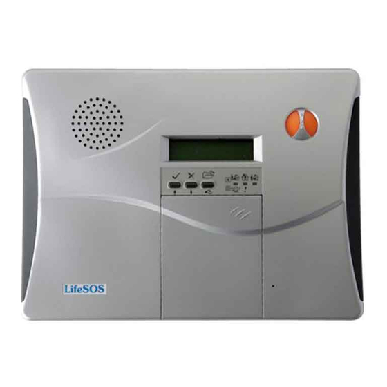
BASE UNIT Front Panel Side Panel Emergency Buttons Speaker To trigger the Emergency help, press both buttons simultaneously. Key Board LCD Display Speaker Volume Control LED status Microphone Rear Panel 3.COM1 5.AUX. Audio 4.COM2 Telephone Line I/P Power adaptor I/P Wire Duct Phone Set Connector 1.ALARM OUT SELECTOR... -
Page 6: Status Indicators
STATUS INDICATORS There are three LED indicators in green, yellow and red colors on the front panel. They represent the system operation mode and alarm/ warning status as listed in the following table. State Yellow Green DISARM Flash AWAY HOME DISARM HOME Flash... -
Page 7: Electrical Installation
Battery 2 (optional) Battery Switch Battery 1 The LS-30 Base Unit can accommodate 2 rechargeable battery packs. Battery pack 1 is 9.6V/800mA(built-in) and Battery pack 2 (optional) is 9.6V/600mA, providing 15-26 hours back up time. 2. Plug in the power adaptor. -
Page 8: Mechanical Installation
MECHANICAL INSTALLATION Placement of the Base Unit It is important for the Base Unit to have a good reception quality for the RF signals transmitted from all the sensors and controllers. Place the Base Unit around the central area at your home or business if possible. ... -
Page 9: User Operation
USER OPERATION... - Page 10 The LS-30 will dial the Latchkey Number (Refer to (4-2-1) Set Telephone Number- Latchkey Number) when these users arm or disarm the system. *Duress Code (User 11,default “8862”): Using this code to operate the system, the LS-30 will send a duress signal to the CMS.
-
Page 11: Start Operation
START OPERATION When you apply the power to the LS-30 for the first time, the LCD display shows “System Reset” & time information. This informs the user about the time of system power on. User can key in “0000DC” to clear the display and entering the Initial State. -
Page 12: Telephone Number Check
(2) System Check Event Check Check By Sequence Check By Date Telephone Number Check (2-1) Voice Check (2-2) Device Check (2-3) Event Check: The Base Unit can store 512 event records in its memory. These events can be checked by time sequence or by entering the date information. - Page 13 (2-1) Telephone Number Check Common 1 Number Common 2 Number Common 3 Number Common 4 Number Panic Number Burglar Number Fire Number Medical Number Special Number Latchkey Number Pager Number Pager Data Show the telephone numbers stored in the memory and their answering types. (refer to (4-2-1) Set Telephone Number to check the usage of different telephone numbers).
- Page 14 (2-2) Voice Check All Voice Common Segment Panic Segment Burglar Segment Fire Segment Medical Segment Special Segment Latchkey Disarm Segment Latchkey Away Segment Playback the pre-recorded voice messages. (refer to (4-3) Set Sound to check the usage of different segments of the voice messages).
-
Page 15: Master Mode
Master Mode Set Bell Door Bell On Device Test Door Bell Off Set Monitor Mode Monitor Mode (Only can be entered in Disarm Mode) Set Partial ARM Disarm Mode COM1 Control COM1 On/Off Need Password? Set Entry Delay (Refer to (4-1) Set Timer- Set Entry Delay.) Set Exit Delay (Refer to (4-1) Set Timer- Set Exit Delay.) Set Clock... - Page 16 Auto Operation will not affected by this setting.) Set Password: Latchkey User: User 9 and User 10 are also called Latchkey Users. The LS-30 will dial the Latchkey Number (Refer to (4-2-1) Set Telephone Number- Latchkey Number) when these users arm or disarm the system.
-
Page 17: Operation Modes Of Ls-30
Enter HOME Mode Note: When you place the LS-30 in Home Mode, the Base Unit will check the status of the Door Magnet sensors. If any of the sensors is still open (for example, you forgot to close the back door), the Base Unit will issue a warning message and show the zone number of the sensor on the LCD display for you to check. -
Page 18: Reaction Of Ls-30 To Different Alarms
REACTION OF LS-30 TO DIFFERENT ALARMS The response of the LS-30 to various alarms and abnormalities is shown below. Burglar alarms can only be issued when the system is in AWAY or HOME mode, while Fire, Panic, Medical and Special alarms can be triggered anytime, regardless of the system operation mode. - Page 19 When you receive a call from the LS-30, you can follow the procedures below to communicate with the system. When you pick up the phone, your voice on the line will trigger the appropriate message from the LS-30 (For the telephone number assigned as voice acknowledgement).
-
Page 20: Dial-In Control
DIAL-IN CONTROL User can control and check with your LS-30 from a phone anywhere in the world by enabling the auto-answer function (refer to (4-2) Set Telephone – Set Auto Answer) and set the ring count number. Notes: 1. If you connect a fax machine or auto-answering machine on the same telephone line, you might need to refer to their manuals and Appendix A-7 to avoid any disoperation. -
Page 21: Installer & Cms Settings
INSTALLER & CMS SETTINGS... -
Page 22: Installer Mode
The Installer Mode is for the installer to set up the system. Enter Installer Password (4) Installer Mode Set Timer (4-1) Set Telephone (4-2) Set Sound (4-3) Set Device (4-4) Set Siren (4-5) Set Misc. (4-6) Set GSM (4-7) (4-1) Set Timer Set Entry Delay Set Exit Delay Set Inner Siren Time... - Page 23 Sensor Supervise Time: 0-24 Hours (default, 12 Hours) The LS-30 is a supervised RF wireless system, meaning supervised sensors send “heartbeat” RF signals to the Base Unit at a certain time interval. If the Base Unit does not receive the RF check signal from a supervised sensor within the Sensor Supervise Time, the LS-30 considers this sensor to be missing and issues a warning message.
-
Page 24: Set Telephone Number
Note: The Ring Count Number is only valid for the Dial-in from the PSTN (land line), if the dial-in is from GSM Module then LS-30 will answer the call immediately. Auto Answer OFF: The Base Unit will not answer the incoming call. - Page 25 (default, Permanent OFF) The LS-30 checks the telephone line voltage and if the line voltage is abnormal, the siren will go off (the Inner Siren should be switched on) to alert the user. (refer to (4-5) Set Siren - Inner Siren.) Permanent OFF: Never check the telephone line state.
- Page 26 5 specific numbers each for different alarms: These will be dialed only when the LS-30 is triggered by the specified alarm. For example, the fire number will be dialed only in a fire alarm. Latchkey number /Power status report number:...
- Page 27 PABX extension number. Each pause is equivalent to a 3-second break. Answering status: Voice /Tone (default, Voice). After dialing, the LS-30 needs an acknowledgement from the called party, either by voice like “Hello” or by a DTMF key tone to ensure the call is connected successfully. With no acknowledgement, the call will be deemed to be failed and will be redialed in the next loop.
-
Page 28: Set Sound
Delay Beep On/OFF Alarm Warning Alarm Warning On/ Off Record Voice: After an alarm call connects successfully, the LS-30 will play the prerecorded voice message that corresponds to the alarm type. The messages should be recorded in their specified segments. - Page 29 Entry Delay Beep: ON/OFF (default, OFF ) Entry Delay Beep ON: The Base Unit will generate beeps during the Entry Delay interval and the beeping speed will get faster until the end of the delay time. (Refer to (4-1) Set Timer-Entry Delay) Entry Delay Beep OFF: No beeps during the Entry Delay interval.
-
Page 30: Set Device
Select Type (4-4-1) Enable State Enroll Device: The LS-30 uses smart code technology. The Base Unit identifies its sensors by their unique IDs, so the Base Unit has to learn all the sensors’ ID code in the initial system setup. (Each sensor has a unique ID that is preset at the factory.) - Page 31 (4-4-1) Change Device Setting Controller Change Burglar Sensor Change Enter Zone Number Fire Sensor Change Enable State Medical Button Change Zone Number Special Sensor Change Switch Control Enable state of devices: Device On Duty/Bypass (default, On Duty): (For all devices) Device On Duty: This sensor is working in the system currently.
- Page 32 by this device. Bell ON/OFF (default, Bell OFF): (For Burglar sensor) Bell ON: In Disarm Mode, the Base Unit will issue a doorbell chime when receiving a trigger signal from this sensor if the Bell status is set to ON in Master Mode (refer to (3) Master Mode - Bell Check - Door Bell.) Bell OFF: Doorbell chime will not sound when receiving a trigger signal from this sensor.
-
Page 33: Set Siren
(4-5) Set Siren Set Inner Siren Inner Siren On/OFF Set Mode Change Chirp Mode Chirp On/OFF Set Tamper Siren In Disarm Siren On/OFF Siren/Relay Test Start Test Inner Siren: ON/OFF (default, ON) Inner Siren On: Enable the Inner Siren. Inner Siren Off: Switch off the Inner Siren. (The Siren keeps silent in alarm and warning states.) The conditions for the Inner Siren to go off when alarm trips: 1. -
Page 34: Set Misc
(4-6) Set Misc. Set RF Jamming Warning Check ROM Version Reset To Factory Default Enter to Reconfirm Emergency Button Assignment Set Inactivity Inactivity ON Inactivity Time Set Password Inactivity OFF Set Modem Ring Count= 1~30 Set SW #16 Arm/Disarm =ON RF Jamming Warning: (default, OFF) Enable or disable the RF jamming warning. -
Page 35: Set Gsm
(4-7) This setting is only valid for the system equipped with a GSM Module (Refer to the Appendix A-6. Connection Diagram for GSM Modem.) Set GSM Display RSSI Set GSM Number GSM Number 1(Mobile phone number) GSM Number 5 (Mobile phone number) GSM ID Note: The PIN code function of the SIM card must be disabled before insert into the GSM Module SIM card slot. -
Page 36: Cms Mode
For PSTN/GSM) Auto Link Check On: The LS-30 will send a check signal to the CMS periodically. Loopback Test: (For PSTN/GSM) The LS-30 will send a link check signal to the CMS immediately. 2 Way Audio: ON/OFF (default=OFF, For PSTN/GSM) 2 Way Audio ON: The Base Unit will enter into 2-way voice communication mode after sending the alarm report to the CMS. -
Page 37: Specifications
SPECIFICATIONS Base Unit Input Power: 12VDC/300mA unregulated or 15VDC/800mA regulated. Standby Current: 50mA. RF : (Follows local regulations, other frequencies as requested) Frequency: 426, 433 and 868MHz Data Modulation: Narrow-band FM or OOK. Power: less than 10mW. Range: about 100m to 300m or more @open field, 25℃ (Depends on sensors and Hardware version). Receiver Type: super heterodyne. -
Page 38: Appendix
APPENDIX A-1. In-coming Message Display. A user or a CMS can send messages to the LS-30 if the Base Unit has been connected to the Internet through the Ethernet Adaptor (optional) by using the HyperSecureLink program. The LCD display will show “Messages Come In” and issue a warning sound periodically to remind the user if any new message has been received by the LS-30 Base Unit. -
Page 39: A-5, Terminal Board Connection
A-5. Terminal Board Connection Wire Arm LED Wire Wire Wire Siren Sensor 3 Indicator Sensor 2 Sensor 1 +12V DC: This terminal provides +12V~15V/300mA output for the customers to connect their own devices. (Note: The output voltage depends on the power adaptor and will be shut down if the external power fails.) ALARM OUT: These two terminals are the Alarm Relay Outputs. -
Page 40: Remote Controller
LS-30 ring count> Fax ring count >TAM ring count. Ex. If the ring count of the LS-30 is 8, the ring count of the Fax should be 6 and ring count of TAM should be 4. 2. Set the operation mode of the Fax machine in TAM mode. (Please refer to the manual of the Fax machine.) - Page 41 Device List Item Device Name Zone No. Location Initial Date of (xx-xx) (User Name) Battery...
Need help?
Do you have a question about the LS-30 and is the answer not in the manual?
Questions and answers