Table of Contents
Advertisement
Quick Links
Advertisement
Table of Contents

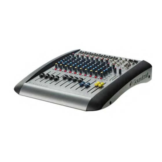
Summary of Contents for GRADAV SoundCraft E8
- Page 1 Soundcraft E8 Mixer...
- Page 3 AFETY GUIDE Safety Symbol Guide Approvals and Notice Warranty Important Safety Instructions Cautions Warnings...
- Page 4 SER G IDE afety ymbol Guide AUTIONS Must be followed carefully to avoid bodily injury. WARNINGS Must be observed to avoid damage to your equipment. NOTES ontain important information and useful tips on the operation of your equipment.
- Page 5 MPORTANT Please read this manual carefully before connecting your mixer to the mains for the first time.
- Page 6 SER G IDE arranty...
- Page 7 MPORTANT SAFETY NSTRUCT ONS AUTIONS • • • • • • •...
- Page 8 SER G IDE • • • • • • • • • ARNINGS • • • • • • •...
- Page 9 ONTENTS Overview The 10 Second Tutor Introduction Advice for Those Who ush the Boundaries Installation & Safety recautions Wiring Up Mono Input Channels Stereo Input Channels Master Section Using Your Spirit ES Console Fitting Rackmount Ears Application 1 Live Sound Reinforcement Application 2 Broadcast Application 3 Recording Application 4 Keyboard SubMixer Application 5 Linking Two Spirit ES Consoles Glossary Typical Specifications Dimensions System Block Diagram Typical Connecting Leads Control osition Markup Sheet...
- Page 10 SER G IDE verview...
- Page 11 HE 10 SECOND U OR MIC INPUT (XLR) WARNING: LINE INPUT (¼” Jack) INSERT POINT (¼” Jack) GAIN CONTROL EQ STAGE AUX SENDS PAN/BAL CONTROL MUTE SWITCH SOLO PEAK LED INPUT CHANNEL FADER MIX OUTPUTS (XLR) MIX INSERTS (¼” Jack) MONITOR O/Ps (¼” Jack) MASTER FADERS MAIN METERS MONITOR CONTROL...
- Page 12 SER G IDE NTRODUCT ON DVICE FOR THOSE WHO PUSH THE BOUND RIES...
- Page 13 NSTALLAT ON AND SAFETY PRECAUT ONS BOUT THIS M NU L NSTALL NG THE M XER • • • • AFETY PRECAUTION he console must only be connected to the Mains Voltage indicated on the rear panel. o avoid the risk of fire, replace the mains fuse only with the correct value fuse, as indicated on the rear panel. eneral Precautions...
- Page 14 SER G IDE IRING UP ic Inputs 1-4 O NOT use UNBALANCE sources with the phantom power switched on. The voltage on pins 2 & 3 of the XLR connector may cause serious damage. BALANCE dynamic mics may normally be used with phantom power switched on (contact your microphone manufacturer for guidance) WARNING ! Start with the input GAIN knob turned fully anticlockwise when plugging high level sources into the LINE input to avoid overloading the input channel or giving you a very loud surprise! ine Input nsert Point...
- Page 15 tereo Inputs 1-10 ix Inserts ix Outputs...
- Page 16 SER G IDE ux Outputs eadphones olarity ( hase) rounding and Shielding • • • • ARNING! Under NO circumstances must the AC power mains earth be disconnected from the mains lead.
- Page 17 ROBLEM SOLVING • • • • • • • • RODUCTS UNDER WARRANTY UT- F-WARRANTY PR DUCTS...
- Page 18 SER G IDE ONO INPUT CHANNELS Mic Input NLY connect condenser microphones with the +48V powering FF, and NLY turn the +48V powering on or off with all output faders D WN, to prevent damage to the mixer or external devices. Line Input Inser t Point...
- Page 19 Equaliser HF EQ MID EQ LF EQ Aux Sends...
- Page 20 SER G IDE MUTE INPUT CHANNEL FADER SOLO PEAK LED...
- Page 21 TEREO INPUT CHANNEL INPUTS STEREO RCA Phono Connectors 3-pole ‘A’ gauge (TRS) sockets...
- Page 22 SER G IDE Mono GAIN QUALIS R HF EQ MF EQ LF EQ AUX SENDS BALANCE MUTE...
- Page 23 FADER SOLO CHANNEL PEAK LED...
- Page 24 SER G IDE aster Section PHANTOM POWER POWER INDICATOR MASTER FADERS MIX OUTPUTS & INSERTS BARGRAPH METERS RECORD OUTPUTS...
- Page 25 PLAYBACK IN PLAYBACK TO MIX MONITOR PLAYBACK MONITOR LEVEL MONITOR OUTPUTS PHONES LEVEL HEADPHONES JACK AUX OUTPUTS (1 & 2) AUX PRE/POST SWITCHES...
- Page 26 SER G IDE SING YO R SPIRIT ES CONSOLE ICROPHONE PLACE ENT N T AL SETUP he front panel drawing on page 8 shows typical initial control positions which is a useful guide to setting up the mixer for the first time. • • • • • Note:...
- Page 27 Note:...
- Page 28 SER G IDE ITTING RACKMOUNT EARS...
- Page 29 PPLIC TIONS PPLIC TION 1 - LIVE SOUND REINFORCEMENT Using Delay in REINFORCEMENT SYS- TEMS...
- Page 30 SER G IDE PPLIC TION 2 - BRO DC ST PPLIC TION 3 - RECORDING...
- Page 31 PPLIC TION 4 - KEYBO RD SUBMIXER PPLIC TION 5 - LINKING TWO SPIRIT ES CONSOLES...
- Page 32 SER G IDE lossary...
- Page 34 SER G IDE YPICAL SPECIFICA IONS oise (22Hz-22kHz measurement bandwidth) Mic EIN @ max gain, 150 W source impedance ................-128dBu Mix @max, faders down ........................ <-85dBu rosstalk (typ. @ 1kHz) Channel mute ...........................>96dB Fader cut-off (rel +10 mark) ......................>96dB Aux send pot offness ........................>86dB requency response Mic/Line input to any output ................
- Page 35 EIGHT ES ..........................7.75 kg (17.09 lbs) VER GE POWER CONSUMPTION (QUIESCENT) ES ............................. 15.5 Watts IN / AX OPERATING TE PERATURE (E SERIES FA ILY) Centigrade / Farenheit ..................0°C - 50°C / 32°F - 122°F...
- Page 36 SER G IDE S Dimensions...
- Page 37 Y TEM BLOCK DIAGRAM...
- Page 38 SER G IDE YPICAL CONNEC ING LEADS...
- Page 40 SER G IDE CONTROL POSITION MARK-UP SHEET...
- Page 42 See our catalogue for details of these and more Dirty Rigger products Gradav Hire and Sales Ltd The Power House Elstree Film Studios Shenley Road Borehamwood WD6 1JG Phone 020 8324 2100 FAX 020 8324 2933 email office@gradav.co.uk Web www.gradav.co.uk...
Need help?
Do you have a question about the SoundCraft E8 and is the answer not in the manual?
Questions and answers