
Related Manuals for GIGA GSP01

Summary of Contents for GIGA GSP01
-
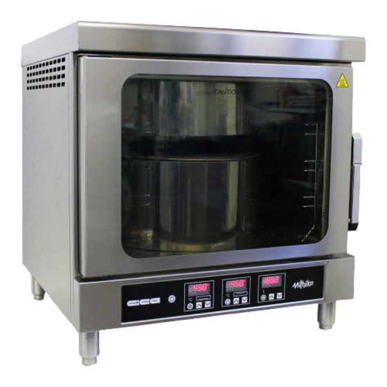
Page 1: Electric Oven
0878_GB_99 Instructions for installation, use e maintenance ELECTRIC OVEN GSP01 941-000-00 01/2012... - Page 2 CHARACTERISTICS Supplied by: Date: Customer Service: e-mail 0878_GB_99 - ELECTRIC OVEN 01/2012 2 · 16...
-
Page 3: Table Of Contents
INDEX Diagram Features of the appliances Technical data 4 Installation instructions 4.1 Safety rules 4.2 Structure, framework and safety 4.3 Assembly 4.3.1 Installation premises 4.3.2 Statutory regulations and technical requirements 4.3.3 Installation 4.3.4 Positioning 4.3.5 Electrical connection and equipotential bonding Operation preparation 5.1 Preparation and Start-up 5.1.1 Start-up... -
Page 4: Diagram
1 - DIAGRAM 607.5 Data plate Equipotential 0878_GB_99 - ELECTRIC OVEN 01/2012 4 · 16... -
Page 5: Technical Data
THE APPLIANCE MUST BE INSTALLED BY QUALIFIED PERSONNEL. 3 - TECHNICAL DATA Model Dimensions in mm. (WxDxH) Voltage rating / Absorption Power Lead wire section GSP01 650x620x626/656 230 V / 12,72 A 2,926 kW 3 x 2.5 mm 0878_GB_99 - ELECTRIC OVEN 01/2012... -
Page 6: Installation Instructions
4 - INSTALLATION INSTRUCTIONS 4.1 Safety rules 4.2 Structure, equipment and safety devices of the unit • Carefully read the safety instructions in this booklet, as they will give you important information about how to install, maintain, Load-bearing structure of stainless steel with 4 feet adjustable in and use the appliance safely. -
Page 7: Installation
4 - INSTALLATION INSTRUCTIONS 4.3.3 Installation illustrated in fig. 1. Caution! Only qualified staff are authorized to install, maintain and put the appliance into service. 4.3.5 Electrical connection and equipotential bonding Caution! Before beginning any electrical connection work, check Caution! The appliance is designed for connection to a volta- that the appliance can support the technical characteristics of the ge supply with the characteristics shown on the technical power supply, by comparing them with the specifications on the... -
Page 8: Instructions For Use
6 - INSTRUCTIONS FOR USE 6.1 Safety, cleaning and repair rulese automatically, this guarantees a long life to all the internal compo- nents and avoid the block of the safety thermostat The three turned on led (2 green and 1 orange) on the display 13 •... -
Page 9: Interior Light
6 - INSTRUCTIONS FOR USE The countdown starts again by pressing button 8. unscrewing the 4 fastening bolts 2 (fig. 3A) inserting the key in the hole, slide the guard forward (movement A) to release the screw When the time counting is on pause the value can be modified by head, remove the guard by lifting it (movement B). - Page 10 6 - INSTRUCTIONS FOR USE 6.4.1 The 2002/96/EC (WEEE) Directive: information to users This informational note is meant only for owners of equipment marked with the symbol shown in fig. A on the adhesive label featuring the technical specifica- tions applied on the actual product (the label also giving the serial number).
-
Page 11: Reserved For Technical Support
7 - RESERVED FOR TECHNICAL SUPPORT 7.1 Parameters configuration 7.2 Lack of voltage when the board is on OFF press contemporaneously buttons 3 and 4. If there’s a lack of voltage, at the next “power up” the board will On the display 11 will come up the written PA, use buttons 6 and 7 be at the same status it was before the lack of voltage. -
Page 12: Replacement Of Spare Parts
7 - RESERVED FOR TECHNICAL SUPPORT 7.3 Signals and emergency alarms In succession the list of the alarms is. Initial Display Cause Result Deactivation of the first adjusting heat and buzzer DISP1 Damaged regulating probe 1 sound Deactivation of the second adjusting heat and buzzer DISP2 Damaged regulating probe 2 sound... - Page 13 7 - RESERVED FOR TECHNICAL SUPPORT 1 2 3 4 5 6 7 8 9 10 11 12 13 14 15 16 17 23 24 25 26 27 28 29 30 31 32 33 Line input terminal board Electronic card Lower temperature sensor Upper temperature sensor Lower heating element 1600W...
- Page 14 NOTES 0878_GB_99 - ELECTRIC OVEN 01/2012 14 · 16...
- Page 15 NOTES 0878_GB_99 - ELECTRIC OVEN 01/2012 15 · 16...
- Page 16 IF THE INSTRUCTIONS CONTAINED IN THIS MANUAL ARE NOT OBSERVED. GIGA GRANDI CUCINE S.r.l. - Via Pisana, 336 - Loc. Olmo - 50018 SCANDICCI (FI) - ITALY Tel. +39 055 722 33 (11 linee r.a.) - Fax +39 055 7310 056 www.gigagrandicucine.it...
Need help?
Do you have a question about the GSP01 and is the answer not in the manual?
Questions and answers