Table of Contents
Advertisement
Quick Links
Advertisement
Table of Contents

Related Manuals for Keysight N6900 Series

Summary of Contents for Keysight N6900 Series
- Page 1 Keysight Advanced Power System N6900/N7900 Series Operating and Service Guide...
-
Page 2: Preliminary Information
Welcome Welcome This document includes user, service, and programming information for the Keysight Advanced Power System (APS) Family. If you have feedback on this document, please contact Keysight at www.keysight.com/find/APS-docfeedback. Preliminary Information Legal and Safety Information Model Features and Options... -
Page 3: Contact Keysight Technologies
Welcome Contact Keysight Technologies You can contact Keysight Technologies for warranty, service, or technical support. In the United States: 800 829 4844 In Europe: 31 20 547 9999 In Japan: 81 426 56 7832 www.keysight.com/find/assist for information on contacting Keysight worldwide, or contact your Keysight Technologies Representative. -
Page 4: Legal And Safety Information
No part of this manual may be reproduced in any form or by any means (including electronic storage and retrieval or translation into a foreign language) without prior agreement and written consent from Keysight Technologies as governed by United States and international copyright laws. - Page 5 Keysight shall not be liable for errors or for incidental or consequential damages in connection with the furnishing, use, or performance of this document or of any information contained herein.
-
Page 6: Safety Notices
Keysight Technologies assumes no liability of the customer’s failure to comply with the requirements. -
Page 7: Safety Symbols
This text indicates that the instrument is an Industrial Scientific and Medical Group 1 Class A product (CISPER 11, Clause 4). ICES/NMB- This text indicates product compliance with the Canadian Interference- Causing Equipment Standard (ICES-001). Keysight N6900/N7900 Series Operating and Service Guide... -
Page 8: Model Features And Options
• • measurements Adjustable sample rate • • Array readback • • External data logging • • Parallel operation • • • • Signal routing • • • • Output lists • • Keysight N6900/N7900 Series Operating and Service Guide... - Page 9 Disconnect relays - no polarity reverse. When installed, appears as option 761 in the "About" screen and on the unit label. This option is included on N7950A and N7970A models. Keysight 14585A Control and Analysis Software Keysight N6900/N7900 Series Operating and Service Guide...
-
Page 10: Specifications And Characteristics
Specifications - Keysight N7900 Series Specifications - Keysight N6900/N7900 High Voltage Series Supplemental Characteristics - Keysight N6900 Series Supplemental Characteristics - Keysight N7900 Series Supplemental Characteristics - Keysight N6900/N7900 High Voltage Series Common Characteristics Output Impedance Graphs Inductive Load Boundary... - Page 11 6 Load lead drop applies to each load lead 7 Time to recover to within the settling band following a load change from 50% to 100% of full load (10 µs rise time) Keysight N6900/N7900 Series Operating and Service Guide...
- Page 12 0.03% +1.4 mV 0.03% +3 mV 0.03% +5.9mV 0.03% +9 mV 0.03% +12mV Current programming & 0.04% +30 mA 0.04% +15 mA 0.04% +8 mA 0.04% +5 mA 0.04% +4 mA measurement accuracy 4 Keysight N6900/N7900 Series Operating and Service Guide...
- Page 13 6 Load lead drop applies to each load lead 7 Time to recover to within the settling band following a load change from 50% to 100% of full load (10 µs rise time) Specifications - Keysight N6900/N7900 High Voltage Series 2 kW Specifications...
- Page 14 Specifications and Characteristics Supplemental Characteristics - Keysight N6900 Series 1 kW Characteristics N6950A N6951A N6952A N6953A N6954A Minimum compliance limits Voltage priority: 100 mA 50 mA 25 mA 16 mA 13 mA Current priority: 9 mV 20 mV 40 mV...
- Page 15 72 V 96 V Accuracy: 0.03% +1.5 mV 0.03% +3 mV 0.03% +6 mV 0.03% +9 mV 0.03% +12 mV Response time: 3 <30 µs <30 µs <30 µs <30 µs <30 µs Keysight N6900/N7900 Series Operating and Service Guide...
- Page 16 6 From start of voltage change to within 0.1% of final full scale value 7 With full resistive load and a current transition from 0.1% to 100% or 100% to 0.1% of rated output 8 Line regulation is guaranteed by design Keysight N6900/N7900 Series Operating and Service Guide...
- Page 17 (peak) Current measurement low 30 mA 17 mA 7 mA 4 mA 2 mA range noise (peak) Output current noise 15 mA 15 mA 15 mA 15 mA 15 mA CC rms: Keysight N6900/N7900 Series Operating and Service Guide...
- Page 18 -112.5 to 112.5A -74.9 to 74.9 A -56.2 to 56.2 A High range -22 to 22 A -11 to 11 A -5.5 to 5.5 A -3.67 to 3.67 A -2.75 to 2.75 A Low range Keysight N6900/N7900 Series Operating and Service Guide...
- Page 19 1 ms Voltage down- programming time 5 90% to 10%: 0.35 ms Settling time: 6 0.8 ms Current up- and down- programming time 7 10% to 90%: 2.5 ms 90% to 10%: 2.5 ms Keysight N6900/N7900 Series Operating and Service Guide...
- Page 20 7 With full resistive load and a current transition from 0.1% to 100% or 100% to 0.1% of rated output 8 Line regulation is guaranteed by design 9 With High Bandwidth setting, no load condition (see Voltage Programming Response) 10 With resistive load condition Supplemental Characteristics - Keysight N6900/N7900 High Voltage Series 2 kW Characteristics N6976A N6977A N7976A N7977A...
- Page 21 with relay on: 38 ms Current priority: 14 ms 14 ms with relay on: 46 ms Line regulation 8 Voltage: < 10 µV < 10 µV Current: < 10 µA < 10 µA Keysight N6900/N7900 Series Operating and Service Guide...
-
Page 22: Common Characteristics
Pin 8 is common (internally connected to chassis ground) Computer Interfaces LXI Core 2011 10/100 Base-T Ethernet (Sockets, VXI-11 protocol, Web user interface) USB USB 2.0 (USB-TMC488 protocol) GPIB GPIB IEEE 488 Language SCPI - 1993, IEEE 488.2 compliant Keysight N6900/N7900 Series Operating and Service Guide... - Page 23 CP+ or PF status bit when the output power exceeds 700W. Typical Weight 1 kw models: 23 lbs. (10.5 kg.) 2 kw models: 34 lbs. (15.5 kg.) N7909A: 18 lbs. (8.2 kg.) Keysight N6900/N7900 Series Operating and Service Guide...
- Page 24 Output Impedance Graphs 1 kW Models 2 kW Models 9 V, 2 kW Output Impedance 9 V, 1 kW Output Impedance 20 V, 2 kW Output Impedance 20 V, 1 kW Output Impedance Keysight N6900/N7900 Series Operating and Service Guide...
- Page 25 Specifications and Characteristics 40 V, 2 kW Output Impedance 40 V, 1 kW Output Impedance 60 V, 2 kW Output Impedance 60 V, 1 kW Output Impedance Keysight N6900/N7900 Series Operating and Service Guide...
- Page 26 The following figures show the boundary limitation for inductive loads and for fast CV/CC mode crossover operation. Operation above the inductive load boundary may result in output instability. The boundary limit represents operating conditions including a 20% current overshoot. Note that increased load resistance allows increased output inductance. Keysight N6900/N7900 Series Operating and Service Guide...
- Page 27 -16.7A -12.5 A (with dissipator) 0.68 V 0.525 V 1.9 V 1.47 V 0.068 V 0.0525 V 0.19 V 0.147 V 0.2 V Minimum sinking 6.8mΩ 10.5mΩ 76 mΩ 89 mΩ 160mΩ resistance Keysight N6900/N7900 Series Operating and Service Guide...
- Page 28 180 mΩ 320 mΩ resistance Voltage Programming Response The following graphs show the output voltage programming response characteristic. These graphs apply for small signals only, under no load condition. N6900 Models N7900 Models Keysight N6900/N7900 Series Operating and Service Guide...
- Page 29 Resolution added to Resolution points spec. (in bits) spec. (in bits) spec. (in bits) 3255 >20 >19 >16 1953 0.00001% 19.9 0.00026% 18.6 0.002% 15.6 0.00076% 17.0 0.0019% 15.7 0.015% 12.7 Keysight N6900/N7900 Series Operating and Service Guide...
- Page 30 0.6 NPLC setting yields an effective resolution of 18.6 bits. Convert the bits to current by applying the bits to the full current rating as follows: 100 A x 2 -18.6 = 252 µA. The measurement resolution is 252 µA. Keysight N6900/N7900 Series Operating and Service Guide...
- Page 31 Specifications and Characteristics Dimension Diagrams - all dimensions in millimeters Power Dissipator Unit Keysight N6900/N7900 Series Operating and Service Guide...
- Page 32 Specifications and Characteristics 1 kW Models Keysight N6900/N7900 Series Operating and Service Guide...
- Page 33 Specifications and Characteristics 2 kW Models Keysight N6900/N7900 Series Operating and Service Guide...
-
Page 34: Operating Information
Operating Information Operating Information Introduction to the Instrument Installing the Instrument Getting Started Using the Advanced Power System Using the Power Assistant Software Keysight N6900/N7900 Series Operating and Service Guide... -
Page 35: Introduction To The Instrument
Output disconnect relays on N7900 models (Polarity reverse relays are not included on models N7950A and N7970A) Measurement features 5.12 μs sample rate Real-time power measurements Amp-Hour and Watt-Hour Measurements Seamless current measurements across ranges on N7900 models Keysight N6900/N7900 Series Operating and Service Guide... -
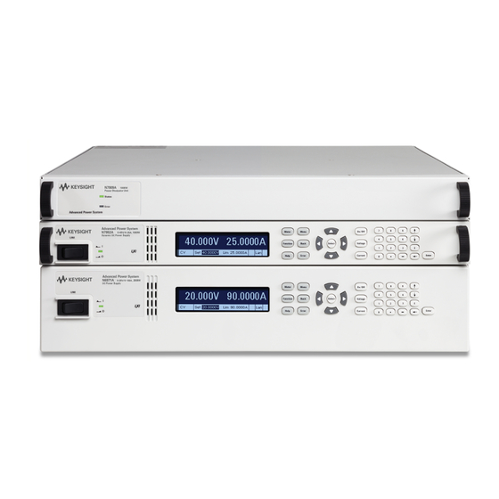
Page 36: Front Panel Display At A Glance
Front panel menu setup for GPIB and LAN parameters LXI Core 2011 compliant, including a built-in Web server SCPI (Standard Commands for Programmable Instruments) compatibility Front Panel at a Glance Front Panel Display at a Glance Keysight N6900/N7900 Series Operating and Service Guide... -
Page 37: Front Panel Keys At A Glance
On/Off switch shows the display status. Green indicates normal operation. Yellow indicates that the display is in screen saver mode. It is also on during the boot-up process. Press any key to exit screen saver mode. Keysight N6900/N7900 Series Operating and Service Guide... - Page 38 The Backspace key deletes digits as it backspaces over them. The Enter key enters a value. If you exit a field without pressing the Enter key, the value is ignored. Press the Help key to get context sensitive help. Keysight N6900/N7900 Series Operating and Service Guide...
-
Page 39: Rear Panel At A Glance
For protection from electrical shock, the power cord ground must not be defeated. If only a two-contact electrical outlet is available, connect the instrument’s chassis ground screw (see above) to a good earth ground. Keysight N6900/N7900 Series Operating and Service Guide... -
Page 40: Power Dissipator At A Glance
2 kW power supplies require two power dissipators to sink the rated output power. P2/P4 Interface The N7909A interface. One interface connection is required for each power dissipator. Only connect the supplied CAT6A cable to the P2 interface. Keysight N6900/N7900 Series Operating and Service Guide... -
Page 41: Front Panel Menu Reference
Specifies number of power line cycles Window Selects Rectangular or Hanning window type Control Initiates, triggers, and aborts acquisitions; displays trig state AhWh Measures or resets amp-hours and watt hours Temp Displays ambient temperature and over-temperature margin Keysight N6900/N7900 Series Operating and Service Guide... - Page 42 Specifies turn-off behavior for all protection conditions Clear Clears protection conditions and displays output status States Reset Resets all instrument settings to the reset (*RST) state SaveRecall Saves and recalls instrument settings PowerOn Selects the power-on instrument state Keysight N6900/N7900 Series Operating and Service Guide...
- Page 43 Signal Displays signal commands Define Defines the individual signal expressions Couple Configures the output on/output couple source Protect Configures the user-protection function Status Configures the user-status source Threshold Configures the signal threshold comparators Keysight N6900/N7900 Series Operating and Service Guide...
- Page 44 Enables/disables the LAN, USB, and GPIB Sanitize Performs NISPOM secure erase of all user data Update Password protected firmware update Options Installs firmware options Password Changes the admin password About Displays model, options, serial number, and firmware Keysight N6900/N7900 Series Operating and Service Guide...
-
Page 45: Installing The Instrument
Installing the Instrument Installing the Instrument Before Installation or Use Single Unit Connections Parallel Connections Series Connections Power Dissipator Connections Interface Connections Rack Mounting Black Box Recorder Keysight N6900/N7900 Series Operating and Service Guide... -
Page 46: Before Installation Or Use
Inspect the Unit When you receive your APS unit, inspect it for any obvious damage that may have occurred during shipment. If there is damage, notify the shipping carrier and nearest Keysight Sales and Support Office immediately. Refer to www.keysight.com/find/assist. -
Page 47: Review Safety Information
The unit must be installed in a location that allows sufficient space of at least 2 inches (51 mm) at the sides and back of the unit for adequate air circulation. Keysight N6900/N7900 Series Operating and Service Guide... -
Page 48: Single Unit Connections
Connect the power cord that was supplied with your unit to the AC mains connector on the rear of the unit. If the wrong power cord was shipped with your unit, contact your nearest Keysight Sales and Support Office. The AC input on the back of your unit is a universal AC input. It accepts nominal line voltages in the range of 100 VAC to 240 VAC. -
Page 49: Output Connections
Paralleled load wires may be required for larger-ampacity power supplies. The following table lists the characteristics of AWG (American Wire Gauge) copper wire. Keysight N6900/N7900 Series Operating and Service Guide... -
Page 50: Single Load Connections
The goal is to always minimize the loop area or physical space between the + and - output leads from the power supply to the load. Keysight N6900/N7900 Series Operating and Service Guide... -
Page 51: Multiple Load Connections
Connect each load to the distribution terminals separately. Remote voltage sensing is recommended under these circumstances. Sense either at the remote distribution terminals or, if one load is more sensitive than the others, directly at the critical load. Keysight N6900/N7900 Series Operating and Service Guide... -
Page 52: Remote Sense Connections
Push in the orange release tabs with a small flat-blade screwdriver to release and insert the sense wires. Keep sense wire size between AWG 16 (1.5 mm 2 ) maximum and AWG 24 (0.2 mm 2 ) minimum. Strip wire insulation back 10 mm. Keysight N6900/N7900 Series Operating and Service Guide... - Page 53 (OV). Reversed sense leads are detected by the negative over-voltage protection function. This function is not programmable and results in the output being disabled due to a negative over-voltage fault (OV-). Keysight N6900/N7900 Series Operating and Service Guide...
-
Page 54: Additional Load Considerations
The APS models are optimized for grounding the negative output terminal. Grounding the positive terminal may result in increased current measurement noise and a reduction in current measurement accuracy. Keysight N6900/N7900 Series Operating and Service Guide... -
Page 55: Parallel Connections
Strip wire insulation back 7 mm. Insert the wires into the connector and tighten the screw terminal. Twist or bundle the wires to reduce noise. Shielding is not required. Connect pins 2 together; connect pins 3 together. Keysight N6900/N7900 Series Operating and Service Guide... -
Page 56: Load, Sense, And Sharing Connections
However, with local sensing, the sharing circuits will work properly only if the voltage drop measured between the local sense points of any unit to the local sense points of any other paralleled unit is less than 0.5% of the maximum voltage rating of the units. Keysight N6900/N7900 Series Operating and Service Guide... - Page 57 Parallel Connections Keysight N6900/N7900 Series Operating and Service Guide...
-
Page 58: Series Connections
Set the negative current limit to its most negative value, thus allowing each instrument maximum capability to protect itself and balance the voltages. Keysight N6900/N7900 Series Operating and Service Guide... -
Page 59: Load, Sense, And Diode Connections
- output leads from the power supply to the load. If the series diode is being used, connect the sense leads as shown below. Without the diode, connect the +s lead directly to the load. Keysight N6900/N7900 Series Operating and Service Guide... -
Page 60: Series Diode Considerations
N6950A/N7950A 381 µF N6970A/N7970A 763 µF N6951A/N7951A 94 µF N6971A/N7971A 188 µF N6952A/N7952A 23 µF N6972A/N7972A 46 µF N6953A/N7953A 11 µF N6973A/N7973A 22 µF N6954A/N7954A 6 µF N6974A/N7974A 12µF N6976A/N7976A 5.5µF N6977A/N7977A 3µF Keysight N6900/N7900 Series Operating and Service Guide... -
Page 61: Power Dissipator Connections
Keep wire size between AWG 10 (6 mm 2 ) maximum and AWG 14 (2.5 mm 2 ) minimum. Wires must carry currents of up to 15 A. Strip wire insulation back 15 mm. Push the wire straight into the oval opening (1). Observe polarity. Keysight N6900/N7900 Series Operating and Service Guide... -
Page 62: Power Dissipator Connections - 1 Kw Units
To release the wire, insert a small screwdriver into the square release-tab opening (2). To release the connector from the unit, push both orange release tabs in together (3) and pull back on the plug. Power Dissipator Connections - 1 kW Units Keysight N6900/N7900 Series Operating and Service Guide... -
Page 63: Power Dissipator Connections - 2 Kw Units
If you are using only one power dissipator with your 2 kW power supply, it does not matter if you are connecting to the upper or lower connectors. In this case, you will only be able to dissipate up to 1 kW of output power. Keysight N6900/N7900 Series Operating and Service Guide... -
Page 64: Interface Connections
Remote Interface Configuration. If you have not already done so, install the Keysight IO Libraries Suite from the Automation-Ready CD that is shipped with your instrument. For detailed information about interface connections, refer to the Keysight Technologies USB/LAN/GPIB Interfaces Connectivity Guide, located on the Automation-Ready CD. -
Page 65: Lan Connections - Site And Private
1. Connect your instrument to the USB port on your computer. 2. With the Connection Expert utility of the Keysight IO Libraries Suite running, the computer will automatically recognize the instrument. This may take several seconds. When the instrument is recognized, your computer will display the VISA alias, IDN string, and VISA address. -
Page 66: Digital Port Connections
169.254.nnn. The front panel Lan indicator will come on when the LAN port has been configured. 2. Use the Connection Expert utility of the Keysight IO Libraries Suite to add the APS models and verify a connection. To add the instrument, you can request the Connection Expert to discover the instrument. If the instrument cannot be found, add the instrument using the instrument’s hostname or IP address. -
Page 67: Rack Mounting
19-inch EIA rack cabinet. Before getting started, check the following list and verify that you have received these items. If anything is missing, please contact your nearest Keysight Sales and Support Office. Items Supplied... - Page 68 Rack Mounting Rack Mounting Keysight N6900/N7900 Series Operating and Service Guide...
-
Page 69: Black Box Recorder
2. Position the BBR board with the connector facing down and snap it into the unit. 3. Replace the access cover and tighten the screws.. 4. Check the box labeled [ ] Option 057 on top of the unit to indicate the option is installed. Keysight N6900/N7900 Series Operating and Service Guide... -
Page 70: Getting Started
Use the left and right navigation keys to navigate to the setting that you wish to change. In the following display, the voltage setting is selected. Enter a value using the numeric keypad. Then press Select. Keysight N6900/N7900 Series Operating and Service Guide... -
Page 71: Set The Output Current
In the display below, the current setting is selected. Use the up and down navigation keys to toggle between the + and - limit entries. Enter a value using the numeric keypad. Then press Select. Keysight N6900/N7900 Series Operating and Service Guide... -
Page 72: Set Over-Voltage Protection
In this case, the top-level menu commands are shown, with the Output command highlighted. The third line indicates which commands are available under the Output command. If there are no lower level commands, a brief description of the highlighted command is displayed. Keysight N6900/N7900 Series Operating and Service Guide... -
Page 73: Enable The Output
Otherwise, the current reading will be zero. The status indicator shows the output’s status. In this case, "CV" indicates the output is in constant voltage mode. For a description of the status indicators, refer to Front Panel Display at a Glance. Keysight N6900/N7900 Series Operating and Service Guide... -
Page 74: Use Built-In Help System
View the help information for displayed messages. Whenever a limit is exceeded or any other invalid configuration is found, the instrument will display a message, including Error code information. Press Meter or Back to exit Help. Keysight N6900/N7900 Series Operating and Service Guide... -
Page 75: Remote Interface Configuration
This instrument supports remote interface communication over three interfaces: GPIB, USB, and LAN. All three interfaces are "live" at power up. To use the interfaces, you must first install the Keysight IO Libraries software located on the Keysight Automation-Ready CD provided with your instrument. Then connect your instrument to your PC. -
Page 76: Lan Configuration
They should also work well for other network configurations. You can also reset the LAN to the as-shipped settings. This returns ALL LAN settings to the as-shipped values and restarts networking. All default LAN settings are listed under Non-volatile Settings. Keysight N6900/N7900 Series Operating and Service Guide... -
Page 77: Modifying The Lan Settings
"192.168.020.011" is actually equivalent to decimal "192.168.16.9" because ".020" is interpreted as "16" expressed in octal, and ".011" as "9". To avoid confusion, use only decimal values from 0 to 255, with no leading zeros. Keysight N6900/N7900 Series Operating and Service Guide... - Page 78 Secondary Address - This field enters the secondary address of the server. Contact your LAN administrator for server details. The same numbering notation applies as for the IP Address. A value of 0.0.0.0 indicates that no default server is defined. Keysight N6900/N7900 Series Operating and Service Guide...
- Page 79 A service name may contain upper and lower case letters, numbers and dashes(-). Each instrument is shipped with a default service name with the format: Keysight-modelnumber-description- serialnumber, where modelnumber is the unit’s 6-character model number (e.g. N6950A), description is the description, and serialnumber is the 10-character serial number located on the label on the top of the unit (e.g.
-
Page 80: Using The Web Interface
If desired, you can control access to the Web interface using password protection. As shipped, no password is set. To set a password, click on the View & Modify Configuration button. Refer to the on-line help for additional information about setting a password. Keysight N6900/N7900 Series Operating and Service Guide... -
Page 81: Using Telnet
Keysight instruments have standardized on using port 5025 for SCPI socket services. A data socket on this port can be used to send and receive ASCII/SCPI commands, queries, and query responses. All commands must be terminated with a newline for the message to be parsed. -
Page 82: Using The Advanced Power System
Sequencing the Output Making Measurements Using Expression Signal Routing Programming the Digital Port External Data Logging (Elog) Black Box Data Recording Current Sharing Operation Current Sinking Operation System-Related Operations Priority Mode Tutorial Current Sharing Tutorial Keysight N6900/N7900 Series Operating and Service Guide... -
Page 83: Programming The Output
Front Panel SCPI Command Press the Voltage key. To set the output voltage to 40 volts: VOLT 40 Enter a value and press Select. Keysight N6900/N7900 Series Operating and Service Guide... -
Page 84: Set The Slew Rate
When set to MAXimum, INFinity, or to a very large value, the slew rate will be limited by the analog performance of the output circuit. Keysight N6900/N7900 Series Operating and Service Guide... - Page 85 0 to 30 µF 0 to 1,500 µF Front Panel SCPI Command Select Output\Advanced\Bandwidth. To select the high bandwidth: VOLT:BWID HIGH1 Select either High1 or Low. Then press Select. To select the low bandwidth: VOLT:BWID LOW Keysight N6900/N7900 Series Operating and Service Guide...
-
Page 86: Set The Output Resistance
In addition to the front panel and SCPI Output On and Output Off commands, you can also use OnCouple, OffCouple, and expression signals to enable and disable the output. Refer to Sequencing the Output for more information. Keysight N6900/N7900 Series Operating and Service Guide... -
Page 87: Configure The Output Relays
AC filter network is still connected to the plus and minus sense and output terminals as shown in the figure below. This AC network is required to meet EMI regulations. Keysight N6900/N7900 Series Operating and Service Guide... - Page 88 4.4 µF 0.2 µF 0.15 Ω N7973A 2 µF 0.94 µF 0.25 Ω N7974A 0.94 µF 0.94 µF 0.25 Ω N7976A 0.5 µF 0.0235 µF 1 Ω N7977A 0.235 µF 0.0235 µF 1 Ω Keysight N6900/N7900 Series Operating and Service Guide...
-
Page 89: Programming Output Protection
Arbs, or load-induced voltage swings (see Output Dynamic Response). If unchecked, these voltage swings could result in premature failure of components in the instrument. EDP protection is always enabled. Keysight N6900/N7900 Series Operating and Service Guide... -
Page 90: Set The Over-Voltage Protection
The delay can be programmed from 0 to 0.255 seconds. You can specify if the OCP delay timer is started by any transition of the output into CC mode, or only at the end of a settings change in voltage, current, or output state. Keysight N6900/N7900 Series Operating and Service Guide... - Page 91 To enable the output watchdog timer: OUTP:PROT:WDOG ON Check Enable Watchdog to enable the watchdog timer. To set the output watchdog timer to 120 seconds: Enter a value in the Watchdog Delay box. OUTP:PROT:WDOG:DEL 120 Then press Select. Keysight N6900/N7900 Series Operating and Service Guide...
- Page 92 N6900 models, the N7900 model relays are N7976A & signaled to open immediately after the protection event occurs. Note that the N7977A) galvanic relays can take up to 20 ms to completely open. Keysight N6900/N7900 Series Operating and Service Guide...
- Page 93 Low Impedance mode for safety reasons. If a power-fail shutdown fault occurs on models with output voltages greater than 60 V, the down- programmer circuit remains enabled for this fault condition for safety reasons. Keysight N6900/N7900 Series Operating and Service Guide...
-
Page 94: Programming Output Transients
The following figure illustrates the transient trigger process. This applies to all transient types. The arrows on the right are specific to List transients. For an overview of the trigger system, refer to Trigger Overview. Keysight N6900/N7900 Series Operating and Service Guide... - Page 95 Front Panel SCPI Command Select Transient\Step. To set a voltage step level of 15 V use: VOLT:TRIG 15 Select the Trig Voltage box to set the voltage. Enter a value and press Select. Keysight N6900/N7900 Series Operating and Service Guide...
- Page 96 It takes a few milliseconds for the instrument to be ready to receive a trigger signal after receiving the INITiate:TRANsient command. If a trigger occurs before the trigger system is ready for it, the trigger will be ignored. Keysight N6900/N7900 Series Operating and Service Guide...
- Page 97 If a bit value of 64 is returned in the query, the TRAN-active bit is true, and the transient action is NOT complete. When the TRAN-active bit is false, the transient action is complete. Refer to Status Tutorial for more information. Keysight N6900/N7900 Series Operating and Service Guide...
-
Page 98: Programming A Step Transient
Lists can contain up to 512 individually programmed steps, and can be programmed to repeat themselves. Only the parameters associated with one of the priority modes, either voltage or current priority, may be list controlled. Keysight N6900/N7900 Series Operating and Service Guide... - Page 99 To generate the voltage list shown in the figure, a list may include the following values: 9, 0, 6, 0, 3, 0: Keysight N6900/N7900 Series Operating and Service Guide...
- Page 100 In a trigger-paced list, the list advances one step for each trigger received. You can also a dwell period if you want to ignore triggers during the dwell time, or guarantee a minimum dwell time between triggered list steps. Keysight N6900/N7900 Series Operating and Service Guide...
- Page 101 Sending the INFinity parameter in the SCPI command makes the list repeat indefinitely. Front Panel SCPI Command Select Transient\List\Repeat. To program the list to repeat twice: LIST:COUN 2 Enter the number of list repetitions (2) and press Select. Keysight N6900/N7900 Series Operating and Service Guide...
-
Page 102: Programming An Arbitrary Waveform
Output Dynamic Response for more information. The output of the Keysight N7900 models can be modulated by the instrument's built-in arbitrary waveform generator. This allows the output to generate complex user-defined voltage or current waveforms. The following are key features of the constant-dwell arbitrary waveform generator: Generate voltage or current arbitrary waveforms. - Page 103 To return the output to the pre-Arb state: ARB:TERM:LAST OFF Select either Return to Start, or Stop at Last Step and press Select. To keep the output at the Arb end point: ARB:TERM:LAST ON Keysight N6900/N7900 Series Operating and Service Guide...
-
Page 104: Sequencing The Output
To circumvent the relay turn on/off delays in the N7900 models a non-volatile OUTPut:RELay:LOCK command can be sent, after which the delays will mirror those seen in the N6900 models. Keysight N6900/N7900 Series Operating and Service Guide... -
Page 105: Turn-On/Turn-Off Delays
These signals provide an additional level of control when sequencing the output on individual and multiple units. The following figure illustrates the programming path when using the OnCouple, OffCouple, and expression signals to control the output. Keysight N6900/N7900 Series Operating and Service Guide... -
Page 106: Sequencing Multiple Units
Specify the Turn-On and Turn-Off Delays for each Unit Turn-on delays can be specified for all coupled units. Any delay sequence can be implemented. There are no restrictions on what the sequence is or what unit comes up first. Keysight N6900/N7900 Series Operating and Service Guide... - Page 107 In this example that actual start of the output turn-on occurs at 60 ms, 70 ms, and 80 ms respectively. You will always need to account for the common delay offset. Keysight N6900/N7900 Series Operating and Service Guide...
- Page 108 Use the delay offset of the Delay offset field in milliseconds. Then press slowest unit to specify the Select. common delay offset OUTP:COUP:DOFF .051 Keysight N6900/N7900 Series Operating and Service Guide...
-
Page 109: Making Measurements
Number of Power Line Cycles (NPLC) You can set the measurement time in number of power line cycles (NPLC). Using an integer number of power line cycles can reduce measurement noise from line frequency sources. Keysight N6900/N7900 Series Operating and Service Guide... -
Page 110: Measurement Windowing
SENS:WIND HANN Seamless Current Measurement Ranging Keysight N7900 models have two current measurement ranges, a high and a low range (see specifications seamless current ranging function ensures that no data is lost due to range switching. Seamless ranging is enabled by default. The commands to enable seamless current measurement ranging are:... - Page 111 Temperature measurements are returned in degrees C. Front Panel SCPI Command Select Measure\Window\Temp. To return the ambient temperature: SYST:TEMP:AMB? Displays the ambient temperature and over-temperature margin in degrees C. To return the over-temperature margin: OUTP:PROT:TEMP:MARG? Keysight N6900/N7900 Series Operating and Service Guide...
- Page 112 To measure the low level of a pulse: MEAS:VOLT:LOW? MEAS:CURR:LOW? To measure the maximum value: MEAS:VOLT:MAX? MEAS:CURR:MAX? To measure the minimum value: MEAS:VOLT:MIN? MEAS:CURR:MIN? To take a measurement and return array data: MEAS:ARR:VOLT? MEAS:ARR:CURR? MEAS:ARR:POW? Keysight N6900/N7900 Series Operating and Service Guide...
-
Page 113: Measurement Triggering
10.24 microseconds are rounded to the nearest 10.24 microsecond increment. Values above 20.48 microseconds are rounded to the nearest 20.48 microsecond increment. Note that Keysight N7900 models also support the NPLC (number of power line cycles) command to configure measurement tint and points as previously discussed. - Page 114 This allows pre- or post-trigger data sampling. To offset the beginning of the acquisition buffer relative to the acquisition trigger: Keysight N6900/N7900 Series Operating and Service Guide...
- Page 115 Selects the unit’s transient system. You must also set up the transient system to generate a trigger out signal. See Programming Output Transients. Voltage Selects an output voltage level. Use the following commands to select a trigger source: Keysight N6900/N7900 Series Operating and Service Guide...
- Page 116 Thus, it will be necessary to initiate the trigger system each time a triggered measurement is desired. Trigger the Measurement The trigger system is waiting for a trigger signal in the initiated state. You can immediately trigger the measurement as follows: Keysight N6900/N7900 Series Operating and Service Guide...
- Page 117 FETC:VOLT:HIGH? FETC:CURR:HIGH? To return the low level of a pulse: FETC:VOLT:LOW? FETC:CURR:LOW? To return the maximum value: FETC:VOLT:MAX? FETC:CURR:MAX? To return the minimum value: FETC:VOLT:MIN? FETC:CURR:MIN? To return array data: FETC:ARR:VOLT? FETC:ARR:CURR? FETC:ARR:POW? Keysight N6900/N7900 Series Operating and Service Guide...
- Page 118 To return DC voltage or current calculated after the trigger indices: FETC:VOLT? [<start_index>, <points>] FETC:CURR? [<start_index>, <points>] To return instantaneous voltage or current data after the trigger indices: FETC:ARR:VOLT? [<start_index>, <points>] FETC:ARR:CURR? [<start_index>, <points>] Keysight N6900/N7900 Series Operating and Service Guide...
-
Page 119: Using Expression Signal Routing
Expressions are built using a large selection of signal inputs along with Boolean operators and programmable delays. The following figure describes the signal routing paths: Keysight N6900/N7900 Series Operating and Service Guide... -
Page 120: Defining Signal Expressions
Define the "expression" using the available will be displayed in the text field. input parameters and operators. Enter the expression using the available See Examples. input names and operators in the text field (see below). Keysight N6900/N7900 Series Operating and Service Guide... - Page 121 Pulses true when the output is starting to turn on OffC event Pulses true when the output is starting to turn off OutpSettled state The output has reached the settled state state The output is regulating in constant voltage mode Keysight N6900/N7900 Series Operating and Service Guide...
-
Page 122: Configuring Threshold Comparators
AHOur level - The measured amp-hour level comparison WHOur level - The measured watt-hour level comparison The following commands define a comparison of the measured voltage to a pre-defined level of 10 V for comparator #1: Keysight N6900/N7900 Series Operating and Service Guide... - Page 123 Select the expression that will trigger the To trigger measurements using expressions: Arb from the CD Arb trigger source TRIG:ACQ:SOUR EXPR<1-8> dropdown list. Measurement trigger sources cannot be selected from the front panel. Keysight N6900/N7900 Series Operating and Service Guide...
- Page 124 Select the expression that will control the User1 status bit from the User1 status source dropdown list. Select the expression that will control the User2 status bit from the User2 status source dropdown list. Keysight N6900/N7900 Series Operating and Service Guide...
-
Page 125: Expression Constraints
Enter "Delay(CV,1) Or (CC And DigPin1)" in the text field. To put it another way, if the above three expressions (Examples 5-7) were all created, you would have only one more expression available for use. Keysight N6900/N7900 Series Operating and Service Guide... -
Page 126: Expression Examples
Use the left/right navigation keys to traverse the text field. Use the backspace key to delete a value. Press Enter when you are finished. Select Transient\TrigSource. Select Expr2 from the Transient trigger source list. Keysight N6900/N7900 Series Operating and Service Guide... - Page 127 Use the left/right navigation keys to traverse the text field. Use the backspace key to delete a value. Press Enter when you are finished. Keysight N6900/N7900 Series Operating and Service Guide...
-
Page 128: Programming The Digital Port
Applies only to pins 4-7. The ONCouple pin synchronizes the output On state between instruments. Only one pin can be configured as an ONCouple. The pin functions as both an input and an output. Keysight N6900/N7900 Series Operating and Service Guide... -
Page 129: Bi-Directional Digital I/O
The digital I/O pin can be used to control both relay circuits as well as digital interface circuits. The following figure illustrates typical relay circuits as well as digital interface circuit connections using the digital I/O functions To configure the pins for digital I/O: Keysight N6900/N7900 Series Operating and Service Guide... - Page 130 Each of the seven pins can be configured to have one of eight user-defined expressions drive the pin. The polarity of the pins can also be configured. Pin 8 is the signal common for the expression pins. To configure the pins for expressions: Keysight N6900/N7900 Series Operating and Service Guide...
- Page 131 Clearing Protection Functions. Pin 2's selected function is ignored. Pin 2 should be connected to the ground of the external circuit. Keysight N6900/N7900 Series Operating and Service Guide...
- Page 132 Inhibit pin to common whenever it is necessary to disable all outputs. Negative polarity must be programmed for all pins in this case. You can also use the Fault output to drive an external relay circuit or signal other devices whenever a protection fault occurs. Keysight N6900/N7900 Series Operating and Service Guide...
- Page 133 Only pins 4 through 7 can be configured as "coupled" pins. The designated pins will function as both an input and an output, with a negative transition on one pin providing the sequence signal to the other pins. The polarity of the pins is not programmable; it is set to NEGative. Keysight N6900/N7900 Series Operating and Service Guide...
- Page 134 Repeat these commands for units 2 and 3. Once configured and enabled, turning the output on or off on any coupled unit will cause all coupled units to turn on or off according to their user-programmed delays. Keysight N6900/N7900 Series Operating and Service Guide...
-
Page 135: External Data Logging (Elog)
The external data logging function can only be programmed using SCPI commands. The Keysight N7900 models have an "external" data logging function (Elog) that lets you continuously log voltage and current measurements. Data logging is external to the instrument because it can only be implemented using SCPI commands. - Page 136 To enable min/max measurements: SENS:ELOG:FUNC:VOLT:MINM ON SENS:ELOG:FUNC:CURR:MINM ON Keysight N7900 models have two current measurement ranges, a high and a low range (see specifications ). A seamless current ranging function ensures that no data is lost due to range switching. Seamless ranging is enabled by default. The commands to enable seamless current measurement ranging are:...
- Page 137 When triggered, the Elog starts placing data in the internal measurement buffer. Because the buffer is only large enough to hold 20 seconds of accumulated measurement your PC application must periodically retrieve (or fetch) the data from this buffer. Keysight N6900/N7900 Series Operating and Service Guide...
-
Page 138: Periodically Retrieve The Data
REAL data is returned as a definite length block, with the byte order specified by the FORMat:BORDer command. Terminate the Elog Front Panel SCPI Command Not available To abort the Elog: ABOR:ELOG Keysight N6900/N7900 Series Operating and Service Guide... -
Page 139: Black Box Data Recording
Logged data is preserved after a power cycle. A time-stamped event is logged each time power is turned on. Logged Data The following output measurements are automatically logged per data record: Average voltage Average current Average power Maximum voltage Maximum current Maximum power Minimum voltage Minimum current Minimum power Keysight N6900/N7900 Series Operating and Service Guide... - Page 140 On the front panel, the snapshot time is specified in hours and percent of hours. In SCPI, the time is specified in seconds. The snapshot always uploads from the most recent data entry on back. Keysight N6900/N7900 Series Operating and Service Guide...
-
Page 141: Snapshot Event Tags
To set the time: Press Select to set the date and time. SYSTem:TIME There will be a slight gap/discontinuity of less than 1 second in the BBR record when the clock is set. Keysight N6900/N7900 Series Operating and Service Guide... -
Page 142: Bbr Alignment
BBR records. Of course, you can combine these last two methods and also tag the digital pulse with a text message in the log to record the meaning of that particular pulse. Keysight N6900/N7900 Series Operating and Service Guide... -
Page 143: Current Sharing Operation
Units of mixed power (1 kW and 2 kW) with the same voltage rating can participate in current sharing. This lets you take advantage of the higher current capability of the 2 kW units. To determine the total load current, you must sum the output current readings of the individual paralleled units. Keysight N6900/N7900 Series Operating and Service Guide... - Page 144 Enable the On Couple/Off Couple function. This setting is saved in non volatile memory. Front Panel SCPI Command Select Output\Sequence\Couple To enable output coupling: OUTP:COUP ON Check Enable to enable output coupling. You do not need to specify a Turn-on delay, Turn-off delay, or Delay offset. Keysight N6900/N7900 Series Operating and Service Guide...
-
Page 145: Program The Output Voltage And Current
Program a Step Function for Additional Output Changes Refer to Programming a Step Transient for details. Connect the Trigger signal to the paralleled units as shown in the previous figure. Then enable the transient Step function. Keysight N6900/N7900 Series Operating and Service Guide... - Page 146 Configure pin 1 as the transient trigger source on all units. Front Panel SCPI Command Select Transient\TrigSource Select the transient trigger source: TRIG:TRAN:SOUR PIN1 Select Pin 1 from the dropdown list. Configure pin 1 as the trigger output for the “master”(Unit 1). Keysight N6900/N7900 Series Operating and Service Guide...
- Page 147 To trigger the Step transient: TRIG:TRAN Select Trigger. Specification Effects The design of the APS has been optimized for parallel operation. Therefore, the effect of paralleled units on the specifications has been kept to a minimum. Keysight N6900/N7900 Series Operating and Service Guide...
-
Page 148: Current Sharing Effects
(CSF), which means that one of the units is no longer sharing current equally. The units will continue to source current until the current limit setting of all units is reached. If the load current attempts to increase above the Keysight N6900/N7900 Series Operating and Service Guide... - Page 149 To determine the total load current, you must sum the output current readings of the individual paralleled units. If you need to determine what the worst case current deviation among paralleled units is, refer to the Current Sharing Tutorial. Keysight N6900/N7900 Series Operating and Service Guide...
-
Page 150: Current Sinking Operation
This is adequate for rapidly down-programming the majority of loads connected to the output. With the addition of Keysight N7909A Power Dissipator Units, the DC power supply can sink up to 100% of it rated current. This allows for the possibility of sinking the power supply’s full rated output current for an indefinite time. This capability is useful with large capacitive loads, or with battery charging/discharging applications. -
Page 151: Querying The Power Dissipator
For 2 kW models, if the negative current limit query returns a value that equals 100% of rated current of the power supply, both power dissipators are connected and recognized. If the value equals 50% of the rated current, only one power dissipator is connected and recognized. Keysight N6900/N7900 Series Operating and Service Guide... -
Page 152: System-Related Operations
When shipped, the power supply is configured to automatically recall the reset (*RST) settings at power-on. However, you can configure the power supply to use the settings you have stored in memory location 0 at power-on. Keysight N6900/N7900 Series Operating and Service Guide... -
Page 153: Front Panel Display
Note that you can specify which measurement functions are displayed at turn-on. Front Panel SCPI Command Select To select a turn-on meter view: System\Preferences\Display\View. DISP:VIEW METER_VI DISP:VIEW METER_VP From the dropdown menu select: DISP:VIEW METER_VIP Voltage,Current; Voltage,Power; or Volt,Curr,Power. Then press Select. Keysight N6900/N7900 Series Operating and Service Guide... - Page 154 “Locked out by internal switch setting” or “Calibration is inhibited by switch setting” appears, the internal switch is set to prevent the password from being changed. Refer to Calibration Switches for more information. Keysight N6900/N7900 Series Operating and Service Guide...
-
Page 155: Priority Mode Tutorial
When the output voltage exceeds the over-voltage protection setting, the output will shut down, the output relays will open, and the OV status bit will be set. Keysight N6900/N7900 Series Operating and Service Guide... -
Page 156: Current Priority
OC status bits will be set. In such a case, it is important to set the voltage limit properly in order prevent this protection shutdown. Keysight N6900/N7900 Series Operating and Service Guide... -
Page 157: Current Sharing Tutorial
In a mixed power configuration, the I is the rated current for the 2 kW unit RATING The following sections describe how to calculate the worst-case deviation from the ideal current for each contributing paralleled unit. Keysight N6900/N7900 Series Operating and Service Guide... -
Page 158: Sharing Deviation For Units Of Equal Power (Either 1 Kw Or 2 Kw)
Gain Error % Offset Error % (K) Gain and Offset Equations 0.267 0.40 G = 0.8%((N – 1)/(1 + 2(N – 1))) K = 1.2%(N – 1.5)/(2N – 1))) 0.320 1.08 0.343 1.71 0.356 2.33 Keysight N6900/N7900 Series Operating and Service Guide... - Page 159 2kW_RATING (1KW_WORST_CASE) (1KW_IDEAL) ∆I =±0.32%(75A) ±1.08%(200A) (1KW_WORST_CASE) ∆I =±2.4A (1KW_WORST_CASE) Repeat the above step for the 2 kW unit. ∆I =±G(I ) ±K(I (2KW_WORST_CASE) (2KW_IDEAL) 2kW_RATING ∆I =±0.32%(150A) ±1.08%(200A) (2KW_WORST_CASE) ∆I =±2.64A (2KW_WORST_CASE) Keysight N6900/N7900 Series Operating and Service Guide...
-
Page 160: Using The Power Assistant Software
1. Download the file AdvancedPSSoftware_Setup.exe and run it on your computer. This will install the Power Assistant software. 2. Connect your instrument to your computer and run the Keysight Connection Expert. Make sure that a connection to your instrument is established. - Page 161 5. Displays the instrument that is being controlled 6. Click to refresh the instrument list 7. Click to launch the Keysight Connection Expert When you expand the front panel controls, the following additional controls appear. These access the same controls that are available from the actual front panel of the instrument.
-
Page 162: Configuring Signal Routing
As shown below, you have now routed the CL+ status signal to Pin 1 on the digital connector. Any time a CL+ (positive current limit) occurs, the signal is routed to digital connector pin 1. Keysight N6900/N7900 Series Operating and Service Guide... -
Page 163: Downloading The Routing
Click on the instrument to select it. Click the green down arrow to download the routing to the instrument (see below). If you have a routing already downloaded that you wish to edit, click the green up arrow to upload the routing to the Power Assistant. Keysight N6900/N7900 Series Operating and Service Guide... -
Page 164: Saving The Routing File
You can save and retrieve routing files on your computer. Click the Disc icon on top of the window to save the file. The default file location is C:\Program Files\Keysight\PowerAssistant. Rename the file, as the default filename is overwritten each time a new file is saved. -
Page 165: Source Icon Descriptions
The remote sense connections are specified level open The measured level is less than the Protection When the signal is true specified level Icon The specified level The output is disabled by an active protection function Keysight N6900/N7900 Series Operating and Service Guide... - Page 166 Pulses true when the transient trigger Pulses true when the acquisition trigger occurs occurs The transient is initiated or in progress Bus Icon Pulses true when a bus trigger is received (either *TRG or GET) Keysight N6900/N7900 Series Operating and Service Guide...
-
Page 167: Operator Icon Descriptions
When the signal is true User When the signal is true Icons Icons Turns the output state on Selects the User1 status bit Turns the output state off Selects the User2 status bit Keysight N6900/N7900 Series Operating and Service Guide... -
Page 168: Signal Routing Examples
5. Select the Digital icon from the Target list to place it onto the work area. Select Pin 1 and Positive polarity from the Digital dropdown list. 6. Move the Pin1 icon toward the output of the Operator icon until the solid yellow connection line appears. Keysight N6900/N7900 Series Operating and Service Guide... - Page 169 5. Select the Transient icon from the Target list to place it onto the work area. Select Trigger from the Transient dropdown list. 6. Move the Transient icon toward the output of the Operator icon until the solid yellow connection line appears. Keysight N6900/N7900 Series Operating and Service Guide...
- Page 170 5. Select the Protect icon from the Target list to place it onto the work area. 6. Move the Protect icon toward the output of the Operator icon until the solid yellow connection line appears. Keysight N6900/N7900 Series Operating and Service Guide...
- Page 171 4. Select the Measure icon from the Target list to place it onto the work area. 5. Move the Measure icon toward the output of the Operator icon until the solid yellow connection line appears. Keysight N6900/N7900 Series Operating and Service Guide...
-
Page 172: Making A Snapshot
The Black Box tab displays the snapshot data file that you retrieved from the instrument. The snapshot always uploads from the most recent data entry on back. The following figure illustrates a sample snapshot file: Keysight N6900/N7900 Series Operating and Service Guide... -
Page 173: Configuring The Display
Click the items that you wish to appear on the display. Scroll down to view all of the items in the list. In the following example, six items are selected. This matches what is shown in the previous figure. Keysight N6900/N7900 Series Operating and Service Guide... - Page 174 Click on the pale blue dots on the timeline to view the user defined message that was placed into the BBR log . Refer to Snapshot Event Tags for information on how to place event messages into the BBR. Keysight N6900/N7900 Series Operating and Service Guide...
-
Page 175: Exporting The Snapshot Data
You can export the snapshot data to an Excel or CSV file. Select Export to export the snapshot data. Select Microsoft Excel to export the data to Excel. Select CSV to save the data in .csv format. The default file location is C:\Program Files\Keysight\PowerAssistant. Saving the Snapshot File You can save and retrieve snapshot files on your computer. -
Page 176: Scpi Programming Reference
The Keysight IO Libraries Suite software is provided on the Keysight Automation Ready CD-ROM provided with your instrument. Installation instructions are provided on the CD-ROM. You can also download the Keysight IO Libraries Suite software, along with IVI-COM and LabVIEW drivers from the Keysight Developer Network at www.keysight.com/find/adn. -
Page 177: Introduction To The Scpi Language
OUTPut [:STATe] OFF|0|ON|1 :DELay :FALL <value>|MIN|MAX :RISE <value>|MIN|MAX :INHibit :MODE LATChing|LIVE|OFF Keywords Keywords, also referred to as headers, are instructions recognized by the instrument. Common commands are also keywords. Keysight N6900/N7900 Series Operating and Service Guide... -
Page 178: Command Separators And Terminators
Semicolons ( ; ) separate commands within the same subsystem. This lets you send several subsystem commands within the same message string. For example, sending the following command string: OUTPut:STATe ON;DELay:RISE 1;FALL 2 is the same as sending the following commands: OUTPut ON OUTPut:DELay:RISE 1 OUTPut:DELay;FALL 2 Keysight N6900/N7900 Series Operating and Service Guide... -
Page 179: Syntax Conventions
Numeric Parameters Commands that require numeric parameters will accept all commonly used decimal representations of numbers including optional signs, decimal points, and scientific notation. If a command accepts only certain specific values, the Keysight N6900/N7900 Series Operating and Service Guide... -
Page 180: Device Clear
Different programming languages and IEEE-488 interface cards provide access to this capability through their own unique commands. The status registers, the error queue, and all configuration states are left unchanged when a Device Clear message is received. Device Clear performs the following actions: Keysight N6900/N7900 Series Operating and Service Guide... -
Page 181: Typical Command Processing Times
Return 25 k point fetch: FETC:VOLT? 32.5 ms 36.7 ms Return 25 k point ASCII array fetch: FETC:ARR:VOLT? 9267 ms 5818 ms Return 25 k point binary array fetch: FETC:ARR:VOLT? 558 ms 537 ms Keysight N6900/N7900 Series Operating and Service Guide... -
Page 182: Commands By Subsystem
Commands by Subsystem Commands by Subsystem ABORt CALibrate DISPlay FETCh FORMat HCOPy IEEE-488 Common INITiate MEASure OUTPut SENSe [SOURce:] CURRent DIGital FUNCtion LIST POWer RESistance STEP VOLTage STATus SYSTem TRIGger Status Tutorial Trigger Tutorial Keysight N6900/N7900 Series Operating and Service Guide... -
Page 183: Abort Subsystem
Note that this command does not turn off continuous triggers if INITiate:CONTinuous:TRANsient ON has been programmed. In this case, the trigger system will automatically re-initiate. Parameter Typical Return (none) (none) Aborts the triggered measurement: ABOR:ACQ Keysight N6900/N7900 Series Operating and Service Guide... -
Page 184: Arb Subsystem
>}|< Block > [SOURce:]ARB:VOLTage:CDWell[:LEVel]? Specifies the level of each point in the Arb. Values are specified in either amperes or volts. The minimum and maximum values depend on the ratings of the unit. Keysight N6900/N7900 Series Operating and Service Guide... - Page 185 Programs a constant dwell time of 0.2 seconds: ARB:CURR:CDW:DWEL 0.2 [SOURce:]ARB:CURRent:CDWell:POINts? [SOURce:]ARB:VOLTage:CDWell:POINts? Returns the number of points in the Arb. Parameter Typical Return (none) <points> Returns the number of current points in the Arb: ARB:CURR:CDW:POIN? Keysight N6900/N7900 Series Operating and Service Guide...
- Page 186 Arb is aborted, the output returns to the settings that were in effect before the Arb started. Parameter Typical Return 0|OFF|1|ON, *RST OFF 0 or 1 Terminate with the output at the last Arb value: ARB:TERM:LAST ON Keysight N6900/N7900 Series Operating and Service Guide...
-
Page 187: Calibrate Subsystem
Calibrates the current programming and measurement. The value selects the range to calibrate. Parameter Typical Return The maximum current of the output range. (none) Calibrates the current of the 10 A range: CAL:CURR 10 Keysight N6900/N7900 Series Operating and Service Guide... - Page 188 Enters the calibration value read by the external meter. You must first select a calibration level for the value being entered. Data values are expressed in base units - either volts or amperes, depending on which function is being calibrated. Parameter Typical Return Numeric value (none) Specify calibration value 0.0237: CAL:DATA 2.37E-2 Keysight N6900/N7900 Series Operating and Service Guide...
- Page 189 To change the password: unsecure calibration memory with old code, then set the new code. If you forget your password, refer to Calibration Switches. This setting is non-volatile; it will not be changed by power cycling or *RST. Keysight N6900/N7900 Series Operating and Service Guide...
- Page 190 Calibrates the local voltage programming and measurement. The value selects the range to calibrate. Parameter Typical Return The maximum voltage of the output range. (none) Calibrates the voltage of the 20 V range: CAL:VOLT 20 Keysight N6900/N7900 Series Operating and Service Guide...
- Page 191 CALibrate Subsystem CALibrate:VOLTage:CMRR Calibrates the voltage common mode rejection ratio. Parameter Typical Return (none) (none) Calibrates the common mode rejection ratio: CAL:VOLT:CMRR Keysight N6900/N7900 Series Operating and Service Guide...
-
Page 192: Current Subsystem
Step is triggered. Units are in amperes. The maximum value depends on the current rating of the unit. The minimum value is the most negative value. Keysight N6900/N7900 Series Operating and Service Guide... - Page 193 ARB causes the output to follow the arbitrary waveform values when a trigger occurs. Parameter Typical Return FIXed|STEP|LIST|ARB, *RST FIXed FIX, STEP, LIST, or ARB Sets the current mode to Step: CURR:MODE STEP Keysight N6900/N7900 Series Operating and Service Guide...
- Page 194 Questionable Condition status register OCP bit is set. Parameter Typical Return 0|OFF|1|ON, *RST OFF 0 or 1 Enable the current protection state: CURR:PROT:STAT ON An over-current condition can be cleared with OUTPut:PROTection:CLEar after the cause of the condition is removed. Keysight N6900/N7900 Series Operating and Service Guide...
- Page 195 The [SOURce:]CURRent:SLEW:MAX command is coupled to the [SOURce:]CURRent:SLEW command. If [SOURce:]CURRent:SLEW sets the rate to MAX or INFinity, [SOURce:]CURRent:SLEW:MAX is enabled. If the slew rate is set to any other value, [SOURce:]CURRent:SLEW:MAX is disabled. Keysight N6900/N7900 Series Operating and Service Guide...
-
Page 196: Digital Subsystem
The port has seven signal pins and a digital ground pin. In the binary-weighted value that is written to the port, the pins are controlled according to the following bit assignments: Bit number Decimal value Bit values corresponding to digital port pins that are not configured as DIO are ignored. Keysight N6900/N7900 Series Operating and Service Guide... - Page 197 POSitive means a rising edge. NEGative means a logical true signal is a voltage low at the pin. For trigger inputs and outputs, NEGative means a falling edge. The pin polarities are saved in non-volatile memory. Parameter Typical Return POSitive|NEGative POS or NEG Sets pin 1 to POSitive polarity: DIG:PIN1:POL POS Keysight N6900/N7900 Series Operating and Service Guide...
- Page 198 Enable BUS triggered signals on the digital pins: CURR:TOUT:BUS ON The query returns 0 (OFF) if the trigger signal will NOT be generated with a BUS trigger command, and 1(ON) if a trigger signal will be generated with a BUS trigger command. Keysight N6900/N7900 Series Operating and Service Guide...
-
Page 199: Display Subsystem
Selects the parameters to display on the front panel. METER_VI displays output voltage and current. METER_VP displays output voltage and power. METER_VIP displays output voltage, current, and power. Parameter Typical Return METER_VI|METER_VP|METER_VIP, METER_VI, METER_VP, or *RST METER_VI METER_VIP To display voltage and power: DISP:VIEW METER_VP Keysight N6900/N7900 Series Operating and Service Guide... -
Page 200: Fetch Subsystem
FETCh[:SCALar]:VOLTage[:DC]? [< >, < >] Returns the averaged measurement. Values returned are either in amperes, volts, or watts. The optional parameters specify a subset starting at <startindex> and of length <points>. Keysight N6900/N7900 Series Operating and Service Guide... - Page 201 Measurement Types. Parameter Typical Return (none) <LOW value> Returns the measured low level voltage FETC:VOLT:LOW? FETCh[:SCALar]:CURRent:MAXimum? FETCh[:SCALar]:VOLTage:MAXimum? FETCh[:SCALar]:CURRent:MINimum? FETCh[:SCALar]:VOLTage:MINimum? Returns the maximum or minimum value. Values returned are either in amperes, or volts. Keysight N6900/N7900 Series Operating and Service Guide...
- Page 202 Parameter Typical Return [<startindex>] the start index <value> [,<value>] [<points>] the number of points or <Block> Returns the measured current array FETC:ARR:CURR? Keysight N6900/N7900 Series Operating and Service Guide...
- Page 203 Parameter Typical Return [<maxrecords>] the number of records returned (1 to <value> 16,384) [,<value>] or <Block> Returns 100 data records FETC:ELOG? 100 Keysight N6900/N7900 Series Operating and Service Guide...
-
Page 204: Format Subsystem
(little-endian). Parameter Typical Return NORMal|SWAPped, *RST NORMal NORM or SWAP Sets the data transfer to Swapped: FORM:BORD SWAP The byte order is used when fetching real data from SCPI measurements. Keysight N6900/N7900 Series Operating and Service Guide... -
Page 205: Function Command
Parameter Typical Return CURRent|VOLTage, *RST VOLTage CURR or VOLT Sets the output regulation to current priority: FUNC CURR Keysight N6900/N7900 Series Operating and Service Guide... -
Page 206: Hcopy Subsystem
Returns the image in GIF format: HCOP:SDUM:DATA? GIF HCOPy:SDUMp:DATA:FORMat BMP|GIF|PNG HCOPy:SDUMp:DATA:FORMat? Specifies the format for front panel images returned. Parameter Typical Return BMP|GIF|PNG, *RST PNG BMP, GIF, or PNG Specify GIF as the image format: HCOP:SDUM:DATA:FORM GIF Keysight N6900/N7900 Series Operating and Service Guide... -
Page 207: Ieee-488 Common Commands
Each set bit of the register enables a corresponding event. All enabled events are logically ORed into the ESB bit of the status byte. The query reads the enable register. Refer to Status Tutorial for more information. Keysight N6900/N7900 Series Operating and Service Guide... - Page 208 Return the instrument's identification string: *IDN? *LRN? Returns a sequence of SCPI commands. These can later be used to put the instrument in the same state that it was in when the *LRN? query was sent. Keysight N6900/N7900 Series Operating and Service Guide...
- Page 209 Other commands cannot be executed until this command completes. *OPT? Returns a string identifying any installed options. A 0 (zero) indicates no options are installed. Parameter Typical Return (none) OPT 760 Returns installed options *OPT? Keysight N6900/N7900 Series Operating and Service Guide...
- Page 210 List data and the calibration state is NOT saved as part of the *SAV operation. Data saved in non-volatile memory, described under Non-Volatile Settings, is not affected by the *SAV command. When shipped, locations 0 through 9 are empty. Keysight N6900/N7900 Series Operating and Service Guide...
- Page 211 Generates an immediate trigger: *TRG *TST? Self-test query. Performs a instrument self-test. If self-test fails, one or more error messages will provide additional information. Use SYSTem:ERRor? to read error queue. See SCPI Error Messages for more information. Keysight N6900/N7900 Series Operating and Service Guide...
- Page 212 Pauses additional command processing until all pending operations are complete. See for more information. Parameter Typical Return (none) (none) Wait until all pending operations complete. *WAI *WAI can only be aborted by sending the instrument a Device Clear command. Keysight N6900/N7900 Series Operating and Service Guide...
-
Page 213: Initiate Subsystem
With initiate continuous disabled, the output trigger system must be initiated for each trigger using the INITiate:TRANsient command. ABORt:TRANsient does not turn off continuous triggers if INITiate:CONTinuous:TRANsient ON has been programmed. In this case, the trigger system will automatically re-initiate. Keysight N6900/N7900 Series Operating and Service Guide... -
Page 214: List Subsystem
Sets the list repeat count. This sets the number of times that a list is executed before it completes. The count range is 1 through 4096. Infinity runs the list continuously. Parameter Typical Return 1 – 4096, *RST 1 <count> Sets the list count to 10: LIST:COUN 10 Keysight N6900/N7900 Series Operating and Service Guide... - Page 215 100 microseconds 26.2144 - 262.144 1 millisecond Parameter Typical Return 0 – 262.144 <list value 1>, <list value 2>, <list value 3> Programs a dwell list. The list contains 3 steps: LIST:DWEL 0.2,0.8,1.6 Keysight N6900/N7900 Series Operating and Service Guide...
- Page 216 OFF (0), and also when the list is aborted, the output returns to the settings that were in effect before the list started. Parameter Typical Return 0|OFF|1|ON , *RST OFF 0 or 1 Terminate with the output at the last step value: LIST:TERM:LAST ON Keysight N6900/N7900 Series Operating and Service Guide...
- Page 217 Parameter Typical Return 0|OFF|1|ON 0 or 1 To generate triggers at the beginning of the second step of a 3-step list: LIST:TOUT:BOST OFF,ON,OFF Keysight N6900/N7900 Series Operating and Service Guide...
- Page 218 Turns the front panel LXI identify indicator on or off. When turned on, the "LAN" status indicator on the front panel blinks on and off to identify the instrument that is being addressed. Parameter Typical Return 0|OFF|1|ON, *RST OFF 0 or 1 To blink the front panel LXI indicator: LXI:IDENT ON Keysight N6900/N7900 Series Operating and Service Guide...
-
Page 219: Measure Subsystem
Takes a measurement; returns the instantaneous voltage. MEASure[:SCALar]:CURRent[:DC]? MEASure[:SCALar]:POWer[:DC]? MEASure[:SCALar]:VOLTage[:DC]? Initiates, triggers, and returns the averaged output measurement. Values returned are either in amperes, volts, or watts. Parameter Typical Return (none) <DC value> Returns the measured DC current MEAS:CURR? Keysight N6900/N7900 Series Operating and Service Guide... - Page 220 <LOW value> Returns the measured low level voltage MEAS:VOLT:LOW? MEASure[:SCALar]:CURRent:MAXimum? MEASure[:SCALar]:VOLTage:MAXimum? MEASure[:SCALar]:CURRent:MINimum? MEASure[:SCALar]:VOLTage:MINimum? Initiates, triggers, and returns the maximum or minimum values of a measurement. Values returned are either in amperes, or volts. Keysight N6900/N7900 Series Operating and Service Guide...
- Page 221 ASCII, returned values are comma separated. When the data format is set to REAL, data is returned as single precision floating point values in definite length arbitrary block response format. Parameter Typical Return (none) <value> [,<value>] or <Block> Returns the measured current array MEAS:ARR:CURR? Keysight N6900/N7900 Series Operating and Service Guide...
-
Page 222: Output Subsystem
Sets the watchdog delay time. :RELay :LOCK [:STATe] 0|OFF|1|ON Enables or disables the locked-closed state of the output relays. :POLarity NORMal|REVerse Sets the polarity of the output relays. :ENABle 0|OFF|1|ON Enables or disables the polarity reversal function. Keysight N6900/N7900 Series Operating and Service Guide... - Page 223 Sets a delay offset to synchronize coupled output state changes. Units are in seconds. Setting this time to the maximum delay offset specified for any instrument that is being coupled will cause all coupled outputs to synchronize to the turn-on times specified by OUTPut:DELay:RISE. This parameter is saved in non-volatile memory. Keysight N6900/N7900 Series Operating and Service Guide...
- Page 224 This command affects on-to-off state transitions. It does NOT affect transitions to off caused by protection functions. Delay times can be programmed with the following resolution: Range in seconds Resolution 0 to 1.023E–4 100 nanoseconds 1.03E–4 to 1.023E–3 1 microsecond 1.03E–3 to 1.023E–2 10 microseconds Keysight N6900/N7900 Series Operating and Service Guide...
- Page 225 When the Inhibit input is false, the output is re-enabled. OFF - The Inhibit input is ignored. Parameter Typical Return LATChing|LIVE|OFF LATC, LIVE, or OFF Sets the Inhibit Input to Live mode: OUTP:INH:MODE LIVE Keysight N6900/N7900 Series Operating and Service Guide...
- Page 226 - as downprogramming is solely determined by the unit's passive internal network. Low Impedance - the output voltage is programmed to zero, then disconnected. Maximum negative current sinking occurs for 2 ms during the turn-off transition. Keysight N6900/N7900 Series Operating and Service Guide...
- Page 227 Enables or disables the I/O watchdog timer. When enabled, the output will be disabled if there is no I/O activity on any remote interface within the time period specified by OUTput:PROTection:WDOG:DELay. The output is latched off but the programmed output state is not changed. Keysight N6900/N7900 Series Operating and Service Guide...
- Page 228 This briefly turns the output off while the output and sense terminal polarities are switched. Parameter Typical Return NORMal|REVerse, *RST NORMal NORM or REV Sets the output polarity to Reverse: OUTP:REL:POL REV Keysight N6900/N7900 Series Operating and Service Guide...
- Page 229 OUTPut:RELay:POLarity:ENABle? Enables or disables the polarity reversal function. This prevents accidental output polarity reversal. This parameter is saved in non-volatile memory. Parameter Typical Return 0|OFF|1|ON 0 or 1 Disables the polarity reversal commands: OUTP:REL:POL:ENAB OFF Keysight N6900/N7900 Series Operating and Service Guide...
-
Page 230: Power Query
100-120 VAC mains. When the maximum available power limit is exceeded, the instrument turns off the output and sets the CP+ status bit. Parameter Typical Return (none) <power limit> Query the power limit: POW:LIM? Keysight N6900/N7900 Series Operating and Service Guide... -
Page 231: Resistance Subsystem
0 to 6.4 Ω (model dependent) | MIN | MAX, *RST 0 Specifies an output resistance of 0.5 ohms: RES 0.5 [SOURce:]RESistance:STATe 0|OFF|1|ON [SOURce:]RESistance:STATe? Enables or disables output resistance programming. Parameter Typical Return 0|OFF|1|ON, *RST OFF 0 or 1 Turns resistance programming on: RES:STAT ON Keysight N6900/N7900 Series Operating and Service Guide... -
Page 232: Sense Subsystem
[:LEVel] <value> Sets the current level for comparator 1,2,3, or 4. :FUNCtion VOLT|CURR|POW|AHO|WHO Sets the sensing function for comparator 1,2,3, or 4. :OPERation GT|LT Sets the comparison type for comparator 1,2,3, or 4. Keysight N6900/N7900 Series Operating and Service Guide... - Page 233 Units are in amperes. The instrument selects the range with the best resolution for the value entered. Parameter Typical Return 0 to maximum <max current> Selects the 2 A range: SENS:CURR:RANG 2 Keysight N6900/N7900 Series Operating and Service Guide...
- Page 234 Enables or disables Elog seamless measurement autoranging. Parameter Typical Return 0|OFF|1|ON, *RST ON 0 or 1 Enable Elog current autoranging: SENS:ELOG:CURR:RANG:AUTO ON SENSe:ELOG:FUNCtion:CURRent 0|OFF|1|ON SENSe:ELOG:FUNCtion:CURRent? SENSe:ELOG:FUNCtion:VOLTage 0|OFF|1|ON SENSe:ELOG:FUNCtion:VOLTage? Enables or disables the Elog current or voltage measurement function. Keysight N6900/N7900 Series Operating and Service Guide...
- Page 235 SENSe:FAULt:STATe 0|OFF|1|ON SENSe:FAULt:STATe? Enables or disables remote sense fault detection. This condition is annunciated by the SF status bit. Parameter Typical Return 0|OFF|1|ON, *RST ON 0 or 1 Disables remote sense fault detection: SENS:FAULt:STATe OFF Keysight N6900/N7900 Series Operating and Service Guide...
- Page 236 Defines the time period between measurement samples. Units are in seconds. Values are rounded to the nearest 20.48 microsecond increment. Below 20.48 microseconds, values are rounded to the nearest 10.24 or 5.12 microsecond increment respectively. Keysight N6900/N7900 Series Operating and Service Guide...
- Page 237 LT (less than) specifies that the signal will be true if the measurements less than the threshold level. Parameter Typical Return GT|LT, *RST GT GT or LT Selects the greater than operation for comparator 1: SENS:THR1:OPER GT Keysight N6900/N7900 Series Operating and Service Guide...
- Page 238 The instrument will revert to a rectangular window when the points exceed 4883. Rectangular window returns measurement calculations with no signal conditioning. Parameter Typical Return HANNing|RECTangular, *RST RECTangular RECT or HANN Specifies a Hanning window function: SENS:WIND HANN Keysight N6900/N7900 Series Operating and Service Guide...
-
Page 239: [Source] Subsystem
Because SOURce subsystem commands are often used without the optional SOURce keyword, these commands are listed by their individual subsystems, below: Subsystems and Commands Using the Optional [SOURce:] Keyword CURRent DIGital FUNCtion LIST POWer:LIMit? RESistance STEP:TOUTput VOLTage Keysight N6900/N7900 Series Operating and Service Guide... -
Page 240: Status Subsystem
Queries the condition register for the Operation Status group. This is a read-only register, which holds the live (unlatched) operational status of the instrument. Reading the Operation Status Condition register does not clear it. Keysight N6900/N7900 Series Operating and Service Guide... - Page 241 When a bit in the PTR register is set to 1, then a 0-to-1 transition of the corresponding bit in the Operation Condition register causes that bit in the Operation Event register to be set. STATus:PRESet sets all bits in the PTR registers and clears all bits in the NTR registers. Keysight N6900/N7900 Series Operating and Service Guide...
- Page 242 STAT:OPER:ENAB STAT:QUES<1|2>:ENAB all defined bits are disabled STAT:OPER:NTR STAT:QUES<1|2>:NTR all defined bits are disabled STAT:OPER:PTR STAT:QUES<1|2>:PTR all defined bits are enabled Parameter Typical Return (none) (none) Preset the Operation and Questionable registers: STAT:PRES Keysight N6900/N7900 Series Operating and Service Guide...
-
Page 243: Status:questionable :Condition
STATus:PRESet clears all bits in the enable register. Parameter Typical Return A decimal value corresponding to the binary-weighted <bit value> sum of the register's bits. Enable bit 2 and 4 in the questionable enable register #1: STAT:QUES1:ENAB 24 Keysight N6900/N7900 Series Operating and Service Guide... - Page 244 If the same bits in both NTR and PTR registers are set to 0, then no transition of that bit at the Questionable Condition register can set the corresponding bit in the Questionable Event register. The value returned is the binary-weighted sum of all bits set in the register. Keysight N6900/N7900 Series Operating and Service Guide...
-
Page 245: Step Command
Specifies whether a trigger out is generated when a transient step occurs. A trigger is generated when the state is on (true). Parameter Typical Return 0|OFF|1|ON , *RST OFF 0 or 1 Sets the step trigger signal to ON: STEP:TOUT ON Keysight N6900/N7900 Series Operating and Service Guide... -
Page 246: System Subsystem
Returns the SCPI version that the instrument complies with. "string" SYSTem:BBR:EVENt < > Adds an event string into the BBR event log. The BBR event log has room for 100,000 events. The maximum length of the event string is 55 characters. Keysight N6900/N7900 Series Operating and Service Guide... - Page 247 Parameter Typical Return (none) 0 or 1 Query the BBR state: SYST:BBR:STAT? SYSTem:BBR:TIME? Returns the length of the Black Box Recorder data. The value is returned in seconds. Keysight N6900/N7900 Series Operating and Service Guide...
- Page 248 Sets the date of the system clock. Specify the year, month, and day. Note that setting the date causes the optional BBR logging function to stop and then start using the new date. Keysight N6900/N7900 Series Operating and Service Guide...
-
Page 249: System:error
If the auto line detect fails because the line is noisy or out of tolerance, it uses a setting of 60 Hz. Parameter Typical Return (none) 50, 60, or 400 Query the power line frequency: SYST:LFR? Keysight N6900/N7900 Series Operating and Service Guide... -
Page 250: System Reboot
MAC address and calibration data) is not erased. After the data is cleared, the instrument is rebooted. This procedure is not recommended for use in routine applications because of the possibility of unintended loss of data. Parameter Typical Return (none) (none) Sanitizes the instrument: SYST:SEC:IMM Keysight N6900/N7900 Series Operating and Service Guide... -
Page 251: System:version
Note that setting the time causes the optional BBR logging function to stop and restart using the new time. SYSTem:VERSion? Returns the SCPI version that the instrument complies with. Cannot be determined from front panel. Keysight N6900/N7900 Series Operating and Service Guide... - Page 252 Typical Return (none) <"version"> Return the SCPI version: SYST:VERS? The command returns a string in the form "YYYY.V", where YYYY represents the year of the version and V represents a version for that year. Keysight N6900/N7900 Series Operating and Service Guide...
-
Page 253: Trigger Subsystem
:SOURce Selects the trigger source for the transient system: BUS |EXTernal |IMMediate <source> |EXPRession<1-8> |PIN<1-7> TRIGger:ACQuire[:IMMediate] TRIGger:ELOG[:IMMediate] TRIGger:TRANsient[:IMMediate] Generates an immediate trigger. This overrides any selected trigger source. TRIGger:ACQuire triggers the acquisition system. Keysight N6900/N7900 Series Operating and Service Guide... - Page 254 Set voltage slope to negative (falling edge): TRIG:ACQ:VOLT:SLOP NEG TRIGger:ACQuire:INDices[:DATA]? Returns the indices into the acquired data where triggers were captured during the acquisition. The number of indices returned is the same as the value returned by TRIGger:ACQuire:INDices:COUNt? Keysight N6900/N7900 Series Operating and Service Guide...
- Page 255 Selects a user-defined expression as the trigger source. PIN<1-7> Selects a digital port pin configured as a trigger input. TRANsient1 Selects the transient system as the trigger source. VOLTage1 Selects an output voltage level. Keysight N6900/N7900 Series Operating and Service Guide...
- Page 256 Selects a digital port pin configured as a trigger input. Parameter Typical Return BUS | EXTernal | IMMediate | PIN<1-7> BUS, EXT, IMM, PIN<n> *RST BUS Select digital port pin 1 as the Elog trigger source: TRIG:ELOG:SOUR PIN1 Keysight N6900/N7900 Series Operating and Service Guide...
- Page 257 Selects a digital port pin configured as a trigger input. Parameter Typical Return BUS | EXTernal | IMMediate | BUS, EXT, IMM, EXPR<n>, PIN<n> EXPRession<1-8>| PIN<1-7>, *RST BUS Select digital port pin 1 as the transient trigger source: TRIG:TRAN:SOUR PIN1 Keysight N6900/N7900 Series Operating and Service Guide...
-
Page 258: Voltage Subsystem
Sets the output voltage to 20 V: VOLT 20 Sets the triggered voltage to 10 V: VOLT:TRIG 10 [SOURce:]VOLTage:BWIDth LOW|HIGH1 [SOURce:]VOLTage:BWIDth? Sets the voltage bandwidth. This lets you optimize output response time with capacitive loads. Keysight N6900/N7900 Series Operating and Service Guide... - Page 259 [SOURce:]VOLTage:PROTection[:LEVel]? [MIN|MAX] Sets the over-voltage protection level. Units are in volts. If the output voltage exceeds the OVP level, the output is disabled and the Questionable Condition status register OV bit is set. Keysight N6900/N7900 Series Operating and Service Guide...
- Page 260 The [SOURce:]VOLTage:SLEW:MAX command is coupled to the [SOURce:]VOLTage:SLEW command. If [SOURce:]VOLTage:SLEW sets the rate to MAX or INFinity, [SOURce:]VOLTage:SLEW:MAX is enabled. If the slew rate is set to any other value, [SOURce:]VOLTage:SLEW:MAX is disabled. Keysight N6900/N7900 Series Operating and Service Guide...
-
Page 261: Status Tutorial
Enable register. The outputs of the Operation Status register group are logically-ORed into the OPERation summary bit (7) of the Status Byte register. Refer to Status Registers for a description of each register. The following table describes the Operation Status register bit assignments. Keysight N6900/N7900 Series Operating and Service Guide... -
Page 262: Questionable Status Group
Output is disabled by the over-temperature protection Output is disabled by the negative over-power limit Output is disabled by a negative OV due to reversed sense leads LIM+ Output is in positive voltage or current limit Keysight N6900/N7900 Series Operating and Service Guide... -
Page 263: Standard Event Status Group
The instrument tried to read the output buffer but it was empty, a new command line was received before a previous query has been read, or both the input and output buffers are full. Keysight N6900/N7900 Series Operating and Service Guide... -
Page 264: Status Byte Register
MSS is set whenever the instrument has one or more reasons for requesting service. *STB? reads the MSS in bit position 6 of the response but does not clear any of the bits in the Status Byte register. Keysight N6900/N7900 Series Operating and Service Guide... -
Page 265: Error And Output Queues
The Output Queue is a first-in, first-out (FIFO) data register that stores instrument-to-controller messages until the controller reads them. Whenever the queue holds messages, it sets the MAV bit (4) of the Status Byte register. Keysight N6900/N7900 Series Operating and Service Guide... -
Page 266: Status Diagram
Status Tutorial Status Diagram Keysight N6900/N7900 Series Operating and Service Guide... -
Page 267: Trigger Tutorial
Destination Description Digital Pin Sends the trigger output signal to the designated digital output pin. See Programming the Digital Port. Keysight N6900/N7900 Series Operating and Service Guide... -
Page 268: Trigger Diagram
Starts the arbitrary waveform. Note that the waveform must first be enabled and initiated. See Programming Output Transients. Note that the trigger system can be combined with user-defined signal expressions to provide control signals for specific applications. See Using Expression Signal Routing. Trigger Diagram Keysight N6900/N7900 Series Operating and Service Guide... -
Page 269: Command Quick Reference
:CMRR Calibrates the voltage common mode rejection ratio. DISPlay Subsystem DISPlay [:WINDow] [:STATe] 0|OFF|1|ON Turns the front panel display on or off. :VIEW METER_VI|METER_VP|METER_VIP Selects the parameters to display on the front panel. Keysight N6900/N7900 Series Operating and Service Guide... - Page 270 :WHOur? [IGNORE_OVLD] Returns the accumulated watt-hours. FORMat Subsystem FORMat [:DATA] ASCII | REAL Specifies the format of the returned data. :BORDer NORMal | SWAPped Specifies how binary data is transferred. HCOPy Subsystem HCOPy Keysight N6900/N7900 Series Operating and Service Guide...
- Page 271 Initiates external data logging. :TRANsient Initiates the transient trigger system. :CONTinuous :TRANsient 0|OFF|1|ON Continuously initiates the transient trigger system. LXI Command :IDENtify :STATe 0|OFF|1|ON Turns the front panel LXI identify indicator on or off. Keysight N6900/N7900 Series Operating and Service Guide...
- Page 272 :DOFFset <value> Sets a delay offset to synchronize coupled output state changes. :MAX :DOFFset? Returns the delay offset required for this instrument. :OFF :SOURce EXPRession<1-8>|NONE Sets the off-couple signal source to an expression. :ON Keysight N6900/N7900 Series Operating and Service Guide...
- Page 273 Sets the recording period of the black box recorder in seconds. :CURRent [:DC] :RANGe [:UPPer] <value> Selects a DC current measurement range. :AUTO 0|OFF|1|ON Enables or disables seamless measurement auto ranging. :ELOG :CURRent [:DC] Keysight N6900/N7900 Series Operating and Service Guide...
-
Page 274: [Source:]Arb Subsystem
Sets the watt-hour level for comparator 1,2,3, or 4. :WHOur :RESet Resets the accumulated watt-hour measurement. :WINDow [:TYPE] HANNing|RECTangular Selects the measurement window. [SOURce:]ARB Subsystem [SOURce:] ARB :COUNt <value>|INFinity Specifies the number of times the Arb repeats. Keysight N6900/N7900 Series Operating and Service Guide... -
Page 275: [Source:]Current Subsystem
Sets the over-current protection delay. :STARt SCHange|CCTRans Specifies what starts the over-current protection delay timer. :STATe 0|OFF|1|ON Enables or disables the over-current protection. :SHARing [:STATe] 0|OFF|1|ON Enables or disables current sharing on paralleled units. :SLEW Keysight N6900/N7900 Series Operating and Service Guide... - Page 276 Specifies the dwell time for each list step. :POINts? Returns the number of list points. :STEP ONCE|AUTO Specifies how the list responds to triggers. :TERMinate :LAST 0|OFF|1|ON Determines the output value when the list terminates. :TOUTput :BOSTep Keysight N6900/N7900 Series Operating and Service Guide...
- Page 277 :TOUTput0|OFF|1|ON Specifies whether a trigger out is generated when a transient step occurs. [SOURce:]VOLTage Subsystem [SOURce:] VOLTage [:LEVel] [:IMMediate] [:AMPLitude] <value> Sets the output voltage when in voltage priority mode. :TRIGgered [:AMPLitude] <value> Sets the triggered output voltage. :BWIDth LOW|HIGH1 Sets the voltage bandwidth. :LIMit Keysight N6900/N7900 Series Operating and Service Guide...
- Page 278 Returns true (1) if the Black Box Recorder is logging. :TIME? Returns the length of the Black Box Recorder data. :COMMunicate :LAN|TCPip:CONTrol? Returns the initial socket control connection port number. :RLSTate LOCal|REMote|RWLock Configures the remote/local state of the instrument. Keysight N6900/N7900 Series Operating and Service Guide...
- Page 279 :TOUTput [:ENABle] Enables measurement triggers to be sent to a digital port pin. 0|OFF|1|ON :VOLTage [:LEVel] Sets the triggered level of the output. <value> :SLOPe Sets the slope of the signal. POSitive|NEGative :ARB Keysight N6900/N7900 Series Operating and Service Guide...
- Page 280 Selects the trigger source for external data logging: BUS |EXTernal |IMMediate| PIN<1-7> <source> :TRANsient [:IMMediate] Generates an immediate trigger. :SOURce Selects the trigger source for the transient system: BUS |EXTernal |IMMediate <source> |EXPRession<1-8> |PIN<1-7> Keysight N6900/N7900 Series Operating and Service Guide...
-
Page 281: Reset State (*Rst)
0.001 ARB:FUNCtion:SHAPe NONE ARB:FUNCtion:TYPE VOLTage ARB:TERMinate:LAST ARB:VOLTage:CDWell:DWELl 0.001 CALibrate:STATe CURRent CURRent:LIMit 1.02% of rating CURRent:LIMit:NEGative -10.2% of rating CURRent:MODE FIXed CURRent:PROTection:DELay 20 ms CURRent:PROTection:DELay:STARt SCHange CURRent:PROTection:STATe CURRent:SHARing CURRent:SLEW CURRent:SLEW:MAXimum CURRent:TRIGgered DIGital:OUTPut:DATA DIGital:TOUTput:BUS DISPlay Keysight N6900/N7900 Series Operating and Service Guide... - Page 282 1 step set to OFF LIST:VOLTage 1 step set to 0.1% of rating LXI:IDENtify OUTPut OUTPut:DELay:FALL OUTPut:DELay:RISE OUTPut:PROTection:MODE LOWZ OUTPut:PROTection:USER OUTPut:PROTection:USER:SOURce NONE OUTPut:PROTection:WDOG OUTPut:PROTection:WDOG:DELay OUTPut:RELay:POLarity NORMal RESistance RESistance:STATe SENSe:CURRent:RANGe:AUTO SENSe:ELOG:CURRent:RANGe:AUTO SENSe:ELOG:FUNCtion:CURRent SENSe:ELOG:FUNCtion:CURRent:MINMax SENSe:ELOG:FUNCtion:VOLTage SENSe:ELOG:FUNCtion:VOLTage:MINMax SENSe:ELOG:PERiod Keysight N6900/N7900 Series Operating and Service Guide...
- Page 283 5.12E–6 SENSe:THReshold<n>:AHOur SENSe:THReshold<n>:CURRent SENSe:THReshold<n>:FUNCtion VOLTage SENSe:THReshold<n>:OPERation SENSe:THReshold<n>:POWer SENSe:THReshold<n>:VOLTage SENSe:THReshold<n>:WHOur SENSe:WINDow RECTangular STEP:TOUTput TRIGger:ACQuire:CURRent TRIGger:ACQuire:CURRent:SLOPe POSitive TRIGger:ACQuire:SOURce TRIGger:ACQuire:TOUTput TRIGger:ACQuire:VOLTage TRIGger:ACQuire:VOLTage:SLOPe POSitive TRIGger:ARB:SOURce TRIGger:ELOG:SOURce TRIGger:TRANsient:SOURce VOLTage 0.1% of rating VOLTage:LIMit 1% of rating VOLTage:MODE FIXed Keysight N6900/N7900 Series Operating and Service Guide...
- Page 284 OUTPut:INHibit:MODE OUTPut:PON:STATe OUTPut:RELay:LOCK OUTPut:RELay:POLarity:ENABle SENSe:BBR:PERiod 0.01 SYSTem:LFRequency:MODE AUTO Front Panel as-shipped settings Front panel lockout password Disabled Firmware update password protected Disabled GPIB address GPIB interface Enabled LAN interface Enabled USB interface Enabled Keysight N6900/N7900 Series Operating and Service Guide...
- Page 285 DC PowerSupply <serial number> LAN service - VXI-11 Enabled LAN service - Telnet Enabled LAN service - mDNS Enabled LAN service - Web server Enabled LAN service - sockets Enabled Web password Blank Keysight N6900/N7900 Series Operating and Service Guide...
-
Page 286: Scpi Error Messages
SCPI Error Messages SCPI Error Messages The Keysight instrument returns error messages in accord with the SCPI standard. Up to 20 errors can be stored in each interface-specific error queue (one each for GPIB, USB, VXI-11, and Telnet/Sockets.) Errors appear in the error queue of the I/O session that caused the error. - Page 287 The instrument is presently running the backup (previous) version of the firmware. 210 Frame NVRAM error A non-volatile RAM error has occurred in the instrument. 212 State file not loaded A previously saved output state file has failed to load. Keysight N6900/N7900 Series Operating and Service Guide...
- Page 288 This may be due to the instrument hardware not being able to support the firmware version. Command Errors (these errors set Standard Event Status register bit #5) -100 Command error Generic syntax error. Keysight N6900/N7900 Series Operating and Service Guide...
- Page 289 -124 Too many digits The mantissa of a numeric parameter contained more than 255 digits, excluding leading zeros. -128 Numeric data not allowed A numeric parameter was received but a character string was expected. Keysight N6900/N7900 Series Operating and Service Guide...
- Page 290 -170 Expression error Generic expression error -171 Invalid expression data The expression data element was invalid. -178 Expression data not allowed Expression data element was sent but is not allowed for this command. Keysight N6900/N7900 Series Operating and Service Guide...
- Page 291 The command could not be executed because of missing hardware, such as an option. -260 Expression error An expression program data element related error occurred. -261 Math error in expression An expression program data element could not be executed due to a math error. Keysight N6900/N7900 Series Operating and Service Guide...
- Page 292 -430 Query DEADLOCKED A condition causing a deadlocked query error occurred. -440 Query UNTERMINATED after indefinite response A query was received in the same program message after a query indicating an indefinite response was executed. Keysight N6900/N7900 Series Operating and Service Guide...
-
Page 293: Compatibility Commands
Code Compatible Commands These Keysight N6700 MPS commands are not required for APS models, but are provided for better compatibility with code written for the N6700 MPS. In most cases these commands either do nothing, or specify a pre-defined parameter that is compatible with the APS models. - Page 294 SYSTem:GROUp:DEFine Does nothing. Groups up to four output channels. SYSTem:GROUp:CATalog? Always returns a "1". Returns the number of grouped channels. SYSTem:GROUp:DELete Does nothing. Ungroups the specified channels. SYSTem:GROUp:DELete:ALL Does nothing. Ungroups all channels. Keysight N6900/N7900 Series Operating and Service Guide...
-
Page 295: Commands And Parameters That Work Differently
Generate a voltage list in voltage priority mode. list. Generate a current list in current priority mode. QUEStionable:STATus? QUEStionable:STATus? Constant current mode indicated by CC bit. Positive current limit indicated by +LIM bit. Keysight N6900/N7900 Series Operating and Service Guide... -
Page 296: Service And Maintenance
Disassembly Types of Service Available If your instrument fails during the warranty period, Keysight Technologies will repair or replace it under the terms of your warranty. After your warranty expires, Keysight offers repair services at competitive prices. Many Keysight products have optional service contracts that extend coverage after the standard warranty expires. - Page 297 If the original shipping container is unavailable, use a container that will ensure at least 10 cm (4 in.) of compressible packaging material around the entire instrument. Use static-free packaging materials. Keysight suggests that you always insure shipments. Cleaning SHOCK HAZARD To prevent electric shock, unplug the unit before cleaning.
-
Page 298: Verification And Calibration
Keysight Technologies Service Center. Keysight Technologies Calibration Services - Your local Keysight Technologies Service Center offers low-cost calibration. The service center uses automated calibration systems that allow Keysight to provide calibration at competitive prices. -
Page 299: Measurement Techniques
If you are using a Keysight 3458A DMM, you can set up the voltmeter to do this automatically. From the instrument’s front panel, program 100 power line cycles per measurement. Press NPLC 100 ENTER. Additionally, turn on auto- calibration (ACAL) and the autorange function (ARANGE). -
Page 300: Recommended Test Equipment And Setups
LeCroy 1855A, DA1850A, or equivalent Terminations 1 – 50Ω BNC termination 2 – 50Ω, 1/8 W termination resistors Power Supply 160 V, 200 A, 2kW Keysight N8754A, N8758A, V, C N8761A * V=Verification C=Calibration Keysight N6900/N7900 Series Operating and Service Guide... -
Page 301: Verification Setups
Verification Setups Keysight N6900/N7900 Series Operating and Service Guide... -
Page 302: Calibration Setups
Calibration Setups Keysight N6900/N7900 Series Operating and Service Guide... -
Page 303: Performance Verification
If the instrument fails any of the tests or if abnormal test results are obtained, try calibrating the unit. If calibration is unsuccessful, return the unit to a Keysight Technologies Service Center. Refer to the... -
Page 304: Constant Voltage Load Effect
“CV Ripple and Noise” and enable the output. Let the oscilloscope run for a few seconds to generate enough measurement points. On the Keysight Infiniium scope, the maximum peak-to-peak voltage measurement is indicated at the bottom of the screen on the right side. Divide this value by 10 to get the CV peak-to-peak noise measurement. -
Page 305: Transient Recovery Time
“Current Programming & Readback, Minimum Current”. Step 4. Program the instrument settings as described in the test record form under “Current Programming & Readback, High Current”. Wait 5 minutes for the temperature to settle. Keysight N6900/N7900 Series Operating and Service Guide... -
Page 306: Constant Current Load Effect
Current Sink Capability Verification This test checks the ability of the power supply to sink up to 10% of its rated output current. If one or more Keysight N7909A Power Dissipators are connected, this test verifies that the power supply can sink up to 100% of its rated output current. -
Page 307: Calibration Procedure
Enter Calibration Mode Front Panel SCPI Command Select System\Admin\Login. CAL:STAT ON <password> Enter your password in the Password field. Then press Select. Keysight N6900/N7900 Series Operating and Service Guide... - Page 308 Calibration Procedure Voltage Calibration Voltage Programming and Measurement Step 1. Connect the voltage input of the Keysight 3458A DMM to the output (see Cal Setup Step 2. Select the voltage programing and measurement calibration. Front Panel SCPI Command Select System\Admin\Cal\Vprog.
-
Page 309: Current Temperature Coefficient Calibration
Step 1. Connect a precision shunt resistor to the output. The shunt resistor must be able to measure the output’s full- scale current (see Cal Setup B). Connect the Keysight 3458A DMM across the shunt resistor. Step 2. Select the temperature coefficient calibration. Front Panel SCPI Command Select System\Admin\Cal\Misc\CurrTC. -
Page 310: Current Calibration
Step 4. Connect a precision shunt resistor to the output. The shunt resistor should be able to measure at least 70% of the output’s full-scale current (see Cal Setup B). Connect the Keysight 3458A DMM across the shunt resistor. Front Panel SCPI Command... -
Page 311: Current Sharing Calibration
This procedure calibrates the Imon signal that is used when units are connected in parallel. Step 1. Connect a short across the + and - output terminals. Connect the Keysight 3458A DMM across pins 2 and 3 of the Sharing connector (see Cal Setup Step 2. - Page 312 Save Calibration and Log Out Front Panel SCPI Command Select System\Admin\Cal\Save. To save calibration data: Select Save to save all calibration data. CAL:SAVE Select System\Admin\Logout To exit calibration mode: to exit calibration mode. CAL:STAT OFF Keysight N6900/N7900 Series Operating and Service Guide...
-
Page 313: Test Record Forms
External supply: 9 V, 22 A 100% of current rating (Isink): Current priority: 9 V, - 100 A Current priority: 9 V, - 200 A External supply: 9 V, 110 A External supply: 9 V, 220 A Keysight N6900/N7900 Series Operating and Service Guide... - Page 314 External supply: 20 V, 11 A 100% of current rating (Isink): Current priority: 20 V, - 50 A Current priority: 20 V, - 100 A External supply: 20 V, 55 A External supply: 20 V, 110 A Keysight N6900/N7900 Series Operating and Service Guide...
- Page 315 External supply: 40 V, 5.5 A 100% of current rating (Isink): Current priority: 40 V, - 25 A Current priority: 40 V, - 50 A External supply: 40 V, 27.5 A External supply: 40 V, 55 A Keysight N6900/N7900 Series Operating and Service Guide...
- Page 316 External supply: 60 V, 3.66 A 100% of current rating (Isink): Current priority: 60 V, - 16.7 A Current priority: 60 V, - 33.3 A External supply: 60 V, 18.37 A External supply: 60 V, 36.6 A Keysight N6900/N7900 Series Operating and Service Guide...
- Page 317 External supply: 80 V, 2.75 A 100% of current rating (Isink): Current priority: 80 V, - 12.5 A Current priority: 80 V, - 25 A External supply: 80 V, 13.75 A External supply: 80 V, 27.5 A Keysight N6900/N7900 Series Operating and Service Guide...
- Page 318 External supply: 9 V, 22 A 100% of current rating (Isink): Current priority: 9 V, - 100 A Current priority: 9 V, - 200 A External supply: 9 V, 110 A External supply: 9 V, 220 A Keysight N6900/N7900 Series Operating and Service Guide...
- Page 319 External supply: 20 V, 11 A 100% of current rating (Isink): Current priority: 20 V, - 50 A Current priority: 20 V, - 100 A External supply: 20 V, 55 A External supply: 20 V, 110 A Keysight N6900/N7900 Series Operating and Service Guide...
- Page 320 External supply: 40 V, 5.5 A 100% of current rating (Isink): Current priority: 40 V, - 25 A Current priority: 40 V, - 50 A External supply: 40 V, 27.5 A External supply: 40 V, 55 A Keysight N6900/N7900 Series Operating and Service Guide...
- Page 321 External supply: 60 V, 3.66 A 100% of current rating (Isink): Current priority: 60 V, - 16.7 A Current priority: 60 V, - 33.3 A External supply: 60 V, 18.37 A External supply: 60 V, 36.6 A Keysight N6900/N7900 Series Operating and Service Guide...
- Page 322 External supply: 80 V, 2.75 A 100% of current rating (Isink): Current priority: 80 V, - 12.5 A Current priority: 80 V, - 25 A External supply: 80 V, 13.75 A External supply: 80 V, 27.5 A Keysight N6900/N7900 Series Operating and Service Guide...
- Page 323 10% of current rating (Isink): Current priority: 120 V, - 1.67 A External supply: 120 V, 1.837 A 100% of current rating (Isink): Current priority: 120 V, - 16.7 A External supply: 120 V, 18.37 A Keysight N6900/N7900 Series Operating and Service Guide...
- Page 324 10% of current rating (Isink): Current priority: 160 V, - 1.25 A External supply: 160 V, 1.375 A 100% of current rating (Isink): Current priority: 160 V, - 12.5 A External supply: 160 V, 13.75 A Keysight N6900/N7900 Series Operating and Service Guide...
- Page 325 10% of current rating (Isink): Current priority: 120 V, - 1.67 A External supply: 120 V, 1.837 A 100% of current rating (Isink): Current priority: 120 V, - 16.7 A External supply: 120 V, 18.37 A Keysight N6900/N7900 Series Operating and Service Guide...
- Page 326 10% of current rating (Isink): Current priority: 160 V, - 1.25 A External supply: 160 V, 1.375 A 100% of current rating (Isink): Current priority: 160 V, - 12.5 A External supply: 160 V, 13.75 A Keysight N6900/N7900 Series Operating and Service Guide...
-
Page 327: Self-Test Procedure
If 0, self-test passed. If 1, self-test failed. indicator comes on. Press the Error key to If self test-fails, use SYSTem:ERRor? display the list of errors. view the self-test error. For a list of errors, see SCPI Error Messages. Keysight N6900/N7900 Series Operating and Service Guide... -
Page 328: Firmware Update
SCPI Command Select System\Admin\Update Not available Check the Must log in as admin box. This requires a user to log into the Admin menu before the firmware update utility performs a firmware update. Keysight N6900/N7900 Series Operating and Service Guide... -
Page 329: Installing Options
14585A - Control and Analysis Software. This software is available for download to your PC at www.keysight.com/find/14585. If you already have the 14585 software installed, make sure you have the latest version. This software is available for free. There is a temporary license key available on the website that allows the 14585A software to be operated on your APS for 30 days. -
Page 330: Instrument Sanitize
To sanitize the N7908A Black Box Recorder drive requires that you removed the board from the instrument and destroy it (see Black Box Recorder). When the BBR board has been removed from the instrument, use the front panel System\BBR\Status menu to remove the BBR accessory from the instrument's option list. Keysight N6900/N7900 Series Operating and Service Guide... -
Page 331: Calibration Switches
The admin/calibration password is reset to 0 when the instrument is first powered Password on. Use this setting if you have forgotten the password. Inhibit All calibration commands are disabled. This is useful where access is guarded by Calibration instrument seals. Keysight N6900/N7900 Series Operating and Service Guide... -
Page 332: Battery Replacement
1. Remove the instrument cover as described under Disassembly. 2. The battery is located near the calibration switches, under two ribbon cables. 3. To access the battery, release the ribbon cables by pulling up on the locking tab. Keysight N6900/N7900 Series Operating and Service Guide... - Page 333 6. Replace the ribbon cables by fully inserting the cables into the connector; then pushing down on the locking tab to secure the cables. 7. Replace the top cover when finished. 8. Reset the date and time (see Clock Setup). Properly dispose of the old battery in accordance with local laws and regulations. Keysight N6900/N7900 Series Operating and Service Guide...
-
Page 334: Electrostatic Discharge (Esd) Precautions
2. Remove the 6 flat-head screws locate on the top, and the 14 pan-head screws on the sides (see figure below). Place the screws in a container so that you do not lose them. 3. Remove off the instrument cover. Keysight N6900/N7900 Series Operating and Service Guide... - Page 335 Disassembly Cover screws Keysight N6900/N7900 Series Operating and Service Guide...
Need help?
Do you have a question about the N6900 Series and is the answer not in the manual?
Questions and answers