
Related Manuals for Samsung MW5694W


Summary of Contents for Samsung MW5694W
-
Page 1: Table Of Contents
MICROWAVE OVEN MW5694W (WHITE) MW5695G (GRAY) SERVICE Manual CONTENTS MICROWAVE OVEN 1. Precaution 2. Specifications 3. Operating Instructions 4. Disassembly and Reassembly 5. Alignment and Adjustments 6. Troubleshooting 7. Exploded Views and Parts List 8. PCB Diagrams 9. Schematic Diagrams... -
Page 2: Precaution
Immediately before handling any semiconductor components or assemblies, CENTRAL SERVICE CENTER drain the electrostatic charge from your body by touching a known earth ground. 10. Service technicians should remove their watches while repairing an MWO. Samsung Electronics... -
Page 3: Specifications
(Use a screwdriver.) 3. High voltage is maintained within specified limits by close-tolerance, safety-related components and adjustments. If the high voltage exceeds the specified limits, check each of the special components. Fig. 1-1. Discharging the High Voltage Capacitor Samsung Electronics... -
Page 4: Specifications
2. Specifications 2-1 Table of Specifications MODEL MW5694W / MW5695G ITEM TIMER 99 MINUTES 99 SECONDS POWER SOURCE 120V/60HZ, AC POWER CONSUMPTION MICROWAVE : 1,400W OUTPUT POWER FROM 100W TO 1000W (10 LEVEL POWER) (IEC-705 TEST PROCEDURE) OPERATING FREQUENCY 2,450MHz... -
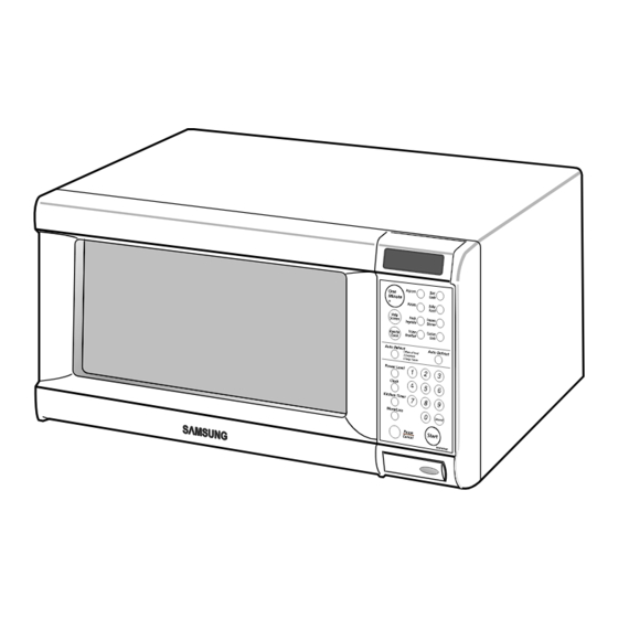
Page 5: Operating Instructions
Pause / Canel Press to pause oven or correct a mistake. 3-2 Features & External Views Light Safety Interlock Holes Ventilation Holes Door Control Panel Door Latches Open Door Push Button Guide Roller Glass Tray 215mm 370mm 517mm 379mm Samsung Electronics... -
Page 6: Disassembly And Reassembly
4-2 Replacement of High Voltage Transformer 1. Discharge the high voltage capacitor. 2. Disconnect all the leads. 3. Remove the mounting bolts. 4. Reconnect the leads correctly and firmly. Samsung Electronics... -
Page 7: Replacement Of Door Assembly
1. Insertion depth of the thin metal plate should be 0.5mm or less. 4-3-4 Removal of Key Door & Spring Remove pin hinge from Door "E" Detach spring from Door "E" and key door. Door "E" Key Door Spring Samsung Electronics... -
Page 8: Replacement Of Fuse/Drive Motor
7. When replacing the drive motor, be sure to remount it in the correct position with the Drive Motor Cover Base Plate coupler. 8. Connect all the leads to the drive motor. 9. Screw the drive motor cover to the base plate with a screw driver. Samsung Electronics... - Page 9 3. When installing new membrane key board, make sure that the surface of escutcheon base is cleaned sufficiently so that any problems (shorted contacts or uneven surface) can be avoided. Membrane Panel Samsung Electronics...
-
Page 10: Alignment And Adjustments
2. Isolate the magnetron from the circuit by disconnecting its leads. 3. A continuity check across the magnetron filament terminals should indicate one ohm or less. 4. A continuity check between each filament terminal and magnetron case should read open. Cooling Fins Samsung Electronics... -
Page 11: High Voltage Capacitor
Door Open Door Closed procedures. ¥ Primary switch 5. Confirm that the gap between the switch ¥ Monitor switch (COM-NC) housing and the switch actuator is no more than ¥ Door Sensing S/W 0.5mm when door is closed. Samsung Electronics... - Page 12 NOTE 1: Variations or errors in the test procedure will cause a variance in the temperature rise. Additional power test should be made if temperature rise is marginal. NOTE 2: Output power in watts is computed by multiplying the temperature rise (step 5) by a factor of 91 times the of centigrade temperature. Samsung Electronics...
-
Page 13: Procedure For Measurement Of Microwave Energy Leakage
; CENTRAL SERVICE CENTER 5-13-2 At least once a year have the microwave energy survey meter checked for accuracy by its manufacturer. Samsung Electronics... -
Page 14: Troubleshooting
H.V.Transformer component test procedure and replace if it is H.V.Capacitor defective. H.V.Diode Magnetron 4. Open or loose wiring of power relay 5. Defective primary latch switch 6. Defective power relay or Ass'y PCB Replace PCB main. Samsung Electronics... - Page 15 Use plastic wrap or cover with a lid. Stir once or twice while cooking foods such as soup, cocoa, or milk. Noise from the turntable motor Noise may result from the motor. Replace turntable motor. when it starts to operate. Samsung Electronics...
-
Page 16: Exploded Views And Parts List
7. Exploded Views and Parts List 7-1 Exploded Views MW5695G MW5694W ONLY Samsung Electronics... -
Page 17: Main Parts List
ASSY-HVD;V2M6,PI9.0,0.05MT DE74-20015G TRAY-COOKING;T6,PI318,1115G,MW5896W DE92-90189Q ASSY-GUIDE ROLLER;CE2933 DE67-60026C COUPLER;PTFE,12G,WHT,MB245 DE61-50579A FOOT;PP,H8,PI15.8x16.1,-,BLK,3RD,- DE80-10001F BASE-PLATE;SGCC,T0.8,W345,L565,MW5896W DE31-10154A MOTOR-DRIVE;M2HJ49ZR02,ST-16,50/60HZ DE71-00015A COVER-CEILING;T0.3,W114.2,L121.5,-,CE2933 DE94-00106A ASSY CONTROL-BOX;120V60HZ,MW5694W/XAA,WHT,IDEO WHITE DE94-00106B ASSY CONTROL-BOX;120V60HZ,MW5695G,D/GRY GRAY DE94-00105A ASSY DOOR;MW5694W/XAA,WHT,IDEO WHITE DE94-00105B ASSY DOOR;MW5695G,D/GRY GRAY DE39-20037H ASSY POWER CORD;120V60HZ,-,L1150,CSA,MW5592W/XAC DE63-90035L CUSHION-RUBBER;T3,W100,L190,-,MW5896W,BLK : Warning... -
Page 18: Door Parts List
WHITE DE34-00014B SWITCH-MEMBRANE;PET,MW5695G,IDEO(D/GRY) GRAY DE72-70221A CONTROL-PANEL;ABS,WHT,140g,102.2x284,MW5694W WHITE DE72-70221B CONTROL-PANEL;ABS,MW5695G,-,-,-,-,D/GRAY GRAY DE67-40180A WINDOW-DISPLAY;SAN,T2,W29.8,77.8,SMG,8g,MW569 DE97-00004A ASSY PCB-MAIN;RA-W3USA-00,MW7490W DE94-00108A ASSY CONTROL-PANEL;120V60HZ,MW5694W/XAA,WHT WHITE DE94-00108B ASSY CONTROL-PANEL;120V60HZ,MW5695G,D/GRY GRAY 7-5 Body Latch Parts List Ref. No. Parts No. Description/Specification Q'ty Remarks DE66-40001C LATCH-BODY;PP(FB53WH),-,39.2G,NTR,-,3RD-W ,MW5592W 3405-000178 SWITCH-MICRO;250V,15A,200gf,SPST-NO 3405-000175 SWITCH-MICRO;250V,15A,200gf,SPST-NO... -
Page 19: Standard Parts List
CV/AIR DE60-10082H SCREW-A;2S-4X12,TOOTHED MGT-TCO DE60-10082H SCREW-A;2S-4X12,TOOTHED MO-FAN DE60-10082H SCREW-A;2S-4X12,TOOTHED P-C-EA DE60-10082H SCREW-A;2S-4X12,TOOTHED PN/OUT DE60-10082H SCREW-A;2S-4X12,TOOTHED S-M-EA DE60-10098A SCREW-ASSY TAP TITE;PH,TC,M4X8,SWRCH18A,ZPC2,GLD,W M/DRIV DE60-10195A SCREW-STAR POLE;TH,*,2,4,12,SWCH18A,ZNC O/PANEL DE60-20063A BOLT-FLANGE;M4,10,ZPC3,YEL,MSWR HI-LOW DE60-20063A BOLT-FLANGE;M4,10,ZPC3,YEL,MSWR HI-UPP DE60-10088A SCREW-TAP PH;PH,M3,L8,FEFZY,PLAIN DE60-10098A SCREW-ASSY TAP TITE;PH,TC,M4X8,SWRCH18A,ZPC2,GLD,W Samsung Electronics... - Page 20 8. P.C.B Diagrams 8-1 P.C.B Diagrams Samsung Electronics...
- Page 21 CONNECTOR-HEADER;BOX,2P/3P,1R,5mm/2.5mm,STRAIGH CN07 DE13-20009A IC;KA7533,DIP IC02 DE39-60001A WIRE-SO COPPER;PI0.6,SN,T,52MM,TAPING_WIRE J01,J02,J04,J05,J10,J11 DE39-60001A WIRE-SO COPPER;PI0.6,SN,T,52MM,TAPING_WIRE J12,J13,J14,J15,J16 DE41-00005A PCB-BOARD;FR-1,MW7496W,W3USA,T1.6X163.88 DE09-00019A IC-MCU;HCD6433724-F15,3RD VFD,-,32K(8BIT) 3501-001050 RELAY-MINIATURE;24VDC,200mW,5A,1FormA,10mS,5mS RY02 3501-001062 RELAY-POWER;24VDC,523.2mW,16A,1FormA,15mS, RY01 3708-000530 CONNECTOR-FPC/FC/PIC;16P,2.54mm,STRAIGHT,SN CN05 DE07-00004A V.F.DISPLAY;SVM-07SS10L,3-RD,74.8*29.0*8.0MM,-,1/6.25 VFD1 DE26-20144A TRANS-L.V;SLV-5574U,120V,60HZ,AC17V/2.7V LVT1 DE30-20016A BUZZER;CBE2220BA,STICK BUZ1 DE61-00005A HOLDER-DIGITRON;NYLON,-,82X33X24,8G,BLK,3RD-W Samsung Electronics...
-
Page 22: Schematic Diagrams
FOR HIGH VOLTAGE LEADS OR AS NOTED ON SPECIAL LEADS. MGT/CVT NOISE FILTER TCO(85/75ûC) MAGNETRON BLK BLU HIGH VOLTAGE DIODE TO CHASSIS PRIMARY SWITCH HIGH VOLTAGE CAPACITOR DOOR SENSING SWITCH MONITOR SWITCH SYMBOL COLOR BOTTOM CENTER ORANGE HIGH VOLTAGE WHITE TRANSFORMER BLACK BLUE WHT BLU POWER RELAY Samsung Electronics...
Need help?
Do you have a question about the MW5694W and is the answer not in the manual?
Questions and answers