Table of Contents
Advertisement
Quick Links
Advertisement
Table of Contents

Related Manuals for Automation Technology GmbH C4 Series

Summary of Contents for Automation Technology GmbH C4 Series
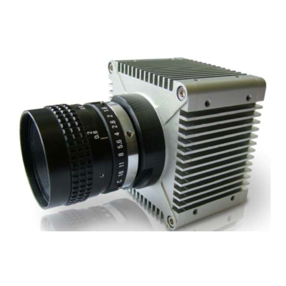
- Page 1 C4-1280-GigE Camera Hardware Reference Manual Rev 1.8 Automation Technology GmbH...
-
Page 3: Table Of Contents
Table Of Contents Table Of Contents C4 Camera Series Overview Introduction....................6 Measuring Principle..................6 Geometry 1 ..................7 Geometry 2 ..................7 Geometry 3 ..................8 Geometry 4 ..................8 The C4-1280-GigE Camera General Specifications ......... 9 Mechanical Drawings ............... 10 The C4-1280-GigE Camera Sensor Specifications.......... - Page 4 The Image Mode (IMG) ..............23 The Maximum Intensity Profile Mode (MAX) ......... 24 The Threshold Mode (TRSH) .............. 25 The Center Of Gravity Mode (COG) ..........26 The High Dynamic Range 3D Feature (HDR-3D) of C4-1280-GigE....27 MultipleSlope Function..............27 Non-Destructive Readout (NDR) Mode ..........
- Page 5 Neither is any liability assumed for damages resulting from the use of the information contained herein. No license is granted under any patents or patent right of AT – Automation Technology GmbH. Trademarks All nationally and internationally recognized trademarks and trade names are hereby acknowledged.
-
Page 6: C4 Camera Series Overview
C4 Camera Series Overview Introduction The C4 camera series is a revolutionary product family of intelligent high speed sensors. It is optimised for 3D profile measurement by means of laser triangulation technique. The 3D profile extraction is performed in the camera by using high performance Field Programmable Gate Array processors. At the same time the 3D profile data is sent to the PC over a Gigabit Ethernet interface (GigE). -
Page 7: Geometry 1
Geometry 1 The laser line is projected perpendicular to the object surface, while the camera views the object under the triangulation angle α. The height resolution can be approximated: ∆Z ≈ ∆X / sin(α) Geometry 2 The camera views the object perpendicularly to its surface, while the laser line is projected under the triangulation angle α. -
Page 8: Geometry 3
Geometry 3 The camera views the object under an angle α, while the laser line is projected under a different angle β. The height resolution can be approximated: ∆Z ≈ ∆X * cos(β) / sin(α + β), in case α= β (direct reflex) : ∆Z ≈ ∆X / 2* sin(α) α... -
Page 9: The C4-1280-Gige Camera General Specifications
The C4-1280-GigE Camera General Specifications Camera Controls Synchonization Modes Free running, Triggered, Software Triggered Exposure Modes Programmable, Pulse controlled Shutter Modes Global Shutter Digital Trigger Input 2 optoisolated inputs, 5V or 24V with C4-I/O-Panel VIL, logic ‚0’ Voltage < 2.5V VIH, logic ‚1’... -
Page 10: Mechanical Drawings
Mechanical Interface Mass (without optics) 340g (C-Mount), 410g (F-Mount) Power connector 20-pin MDR Ethernet connector RJ45 Illunimation control connector 5-pin M9 Electrical Interface Input Voltage 10 - 24V DC Power consumption <10W Operating Temperature 0°C to +50°C (non condensing) Output Data Interface Gigabit Ethernet (IEEE 802.3) Communication Protocol GigE Vision with GeniCam... -
Page 11: The C4-1280-Gige Camera Sensor Specifications
The C4-1280-GigE Camera Sensor Specifications Parameters Specifications Sensitivity at peak response 20000 LSB / µJ / cm² @680nm Resolution 1280 x 1024 Pixel Size 14µm x 14µm Sensor Size 17.92mm x 14.34mm, diagonal: 22.95mm Optics 1” Sensor ADC Resolution 10 bit Sensor Dynamic Range 90dB Max. -
Page 12: C4-1280-Gige Camera Operational Reference
C4-1280-GigE Camera Operational Reference C4-1280-GigE Camera GenICam Features DeviceInformation Name Rev. Interface Access Description DeviceVendorName IString The name of the device vendor. DeviceModelName IString The name of the device model. DeviceManufacturerInfo IString Additional info from manufacturer about this device. DeviceVersion IString A string identifying the version of the device. -
Page 13: Acquisitioncontrol
Name Rev. Interface Access Description ReverseY IBoolean When set to true, this parameter flips the image vertically. OffsetX IInteger X Offset of AOI TestImageSelector IEnumeration Selection of the test image to be used. - Off - GreySensorColumnPattern LinePitch IInteger Distance between consecutive lines in bytes. PixelDynamicRangeMin IInteger Minimum pixel value sent by the camera. -
Page 14: Cameracontrols - Modeandalgorithmcontrols - Aoitracking
Name Rev. Interface Access Description immediately after detecting a Gauss falling edge. Clear the result, if the position value is invalid. ClearInvalidPos IBoolean Enable validation of position value using tolerances for width and sum of intensity. Perform validation at the end of scan of image column. Invalid position values are set to zero in all DCs. -
Page 15: Cameracontrols - Sensorcontrols - Advancedsensorsettings
NDRMode IEnumeration Non Destructive Readout (NDR) Mode: - Off - On - SingleFrameMode. NDRSingleFrameNumber IInteger NDR single frame number. NDRExposureTimeAbs_1 IInteger NDR exposure time 1. NDRExposureTimeAbs_2 IInteger NDR exposure time 2. NDRExposureTimeAbs_3 IInteger NDR exposure time 3. NDRExposureTimeAbs_4 IInteger NDR exposure time 4. CameraControls –... -
Page 16: Cameraio
CameraIO Name Rev. Interface Access Description Input1 IEnumeration Lists the input signals available for IN1: - Input1_Unused. - Input1_FrameStart - Input1_EnableFrame - Input1_Trigger Input2 IEnumeration Lists the input signals available for IN2: - Input2_Unused. - Input2_StopFrame - Input2_Trigger Output1 IEnumeration Selects the output signal for OUT1: - Out1_IntegrationActive - Out1_SequencerActive... -
Page 17: Triggercontrols - Resolverrs422
Name Rev. Interface Access Description - EncoderResolverInterfaceRS422. ClearTriggerOverrun ICommand Command to clear the trigger overrun flag. TriggerControls – ResolverRS422 Name Rev. Interface Access Description TriggerDivider IInteger Trigger divider. TriggerCoord IInteger Resolver trigger coordinates TriggerDirectionMode IBoolean A sensor image is triggered when the internal pulse counter is countdown to 0. - Page 18 Name Rev. Interface Access Description GevDeviceModeCharacterSet IEnumeration This feature represents the character set of all boot strap strings: - CharacterSet_UTF8 GevInterfaceSelector IEnumeration Indicates the index of the network interface to configure: - EnumEntry_GevInterfaceSelector_Interface_0 GevMACAddress IInteger 48-bit MAC address of the selected interface GevSupportedIPConfigurationLLA IBoolean Indicate if LLA (Auto-IP) is supported by the selected...
-
Page 19: Usersets
UserSets Name Rev. Interface Access Description UserSetSelector IEnumeration Selects the feature User Set to load, save or configure: - Factory - UserSet1 - UserSet2 - UserSet3 UserSetLoad[UserSetSelector] ICommand Loads the User Set specified by UserSetSelector to the device and makes it active. UserSetSave[UserSetSelector] ICommand Saves the selected User Set specified by... - Page 20 Name Rev. Interface Access Description device file storage and the FileAccessBuffer. FileOperationStatus IEnumeration Represents the file operation execution status: - Success - Failure FileOperationResult IInteger Represents the file operation result. For Read or Write operations, the number of successfully read/written bytes is returned. FileSize IInteger Represents the size of the selected file in bytes.
-
Page 21: The Genicam Features Configuration Of C4-1280-Gige
The GenICam Features Configuration of C4-1280-GigE Due to dependencies of the XML nodes of C4-1280-GigE registers, it is recommended to follow a specific order, when configuring the GenICam features of the camera. The list shown below, generated as a CXC file by the CX-Explorer, demonstrates an example of the correct write order: CameraMode CenterOfGravity ProfileTriggerMode... - Page 22 MemH 3.2 MemL 2.55 BlackLevelAdjust 80 EnableDC0 EnableDC1 EnableDC1TrshWidth EnableDC1Width EnableDC1Flags 0 EnableDC2 EnableDC2TrshSP EnableDC0Shift 0 AcquisitionFrameCount AcquisitionMode Continuous Output1 Out1_SequencerActive Output2 Out2_IntegrationActive LaserPower TurnLaserOn TurnLaserOnAuto Output1MinPulseWidth 22 • C4-1280-GigE Camera Hardware Reference Manual Rev. 1.8...
-
Page 23: The C4-1280-Gige Camera Algorithms
The C4-1280-GigE Camera Algorithms The C4-1280-GigE camera can be operated both in a variety of 3D profile modes and in image mode. The current operation mode can be chosen by setting the parameter Camera Controls→ ModeAndAlgorithmControls→CameraMode. The frame rate can be increased in all camera modes by reducing the AOI size. In the image mode the frame rate is limited by the output rate of the camera interface (GigE). -
Page 24: The Maximum Intensity Profile Mode (Max)
The Maximum Intensity Profile Mode (MAX) In this mode the position of the maximum intensity of laser beam profile is calculated. The result includes the position value of the maximum (P ) as well as the maximum intensity value (I AOI_TRSH The calculation of position value is performed with simple pixel accuracy, i.e. -
Page 25: The Threshold Mode (Trsh)
The Threshold Mode (TRSH) In this mode the position of left (P ) and right (P ) edge of the laser beam profile are detected for a given threshold value of intensity AOI_TRSH. AOI_TRSH TRSH The position value of the laser line is approximated: P = (P ) / 2. -
Page 26: The Center Of Gravity Mode (Cog)
The Center Of Gravity Mode (COG) In this mode the center of gravity of laser beam profile is calculated. For this purpose the following parameters are computed: Position value of the left edge of laser beam profile for a given intensity threshold value P Sum of intensity value I = ∑... -
Page 27: The High Dynamic Range 3D Feature (Hdr-3D) Of C4-1280-Gige
The High Dynamic Range 3D Feature (HDR-3D) of C4- 1280-GigE One of the most powerful features of C4-1280-GigE is the HDR-3D (High Dynamic Range) functionality, which allows to scan materials and surfaces with inhomogeneous reflection properties. Using HDR-3D the dynamic range of image intensity is extended up to 90dB, thus avoiding intensity saturation. - Page 28 SingleSlope-Modus (default mode) Intensity Intensity Saturation Saturation Integration Integration time time DualSlope mode Intensity Intensity Saturation Saturation DS Reset DS Reset Level Level DS Reset DS Reset Integration Integration Time Time time time TripleSlope mode Intensity Intensity Saturation Saturation TS Reset TS Reset Level Level...
- Page 29 Application of MultipleSlope function in the image of a laser line projected on a surface with non- homogeneous reflectivity (black & white pattern) SingleSlope DualSlope TripleSlope 1100 1100 1100 1000 1000 1000 Sensor row # Sensor row # Sensor row # •...
-
Page 30: Non-Destructive Readout (Ndr) Mode
Non-Destructive Readout (NDR) Mode With the NDR mode it is possible to readout of up to 4 images at different integration levels during one exposure period. The principle is comparable to multiple scans with different integration times with the advantage of taking all data during one single integration period. -
Page 31: The Data Output Format Of C4-1280-Gige
The Data Output Format of C4-1280-GigE The image and 3D data output is performed by selecting the data channel DC0-DC2 (node Camera Controls→DataOutput). Depending on the algorithm the data can be acquired by enabling the corresponding output Data Channel (DC). Every DC is saved in a new image row. The bit depth of output data depends on the selected algorithm. -
Page 32: The Output Frame Structure
The Output Frame Structure Depending on configuration, the C4-1280-GigE writes data to the output frame according to following scheme: 1) NDR mode disabled (NDRMode=”Off”) for (profile_idx=1; profile_idx <=ProfilesPerFrame; profile_idx ++) for(AOI_idx=1; AOI_idx<=NumAOIs; AOI_idx++) if(EnableDC0==true) write_data_of_DC0 (AOI_idx); if(EnableDC1==true) write_data_of_DC1 (AOI_idx); if(EnableDC2==true) write_data_of_DC2 (AOI_idx);... - Page 33 Examples of Output Frame Structure 1) Configuration with single AOI, single DC, disabled NDR mode and output of 6 profiles resulting to a frame height of 6 rows: ProfilesPerFrame=10 NumAOIs=1 EmableDC0= false, EnableDC1=false EnableDC2=true NDRMode=”Off” Row # Description Profile # Data of DC2 readout from AOI1 Data of DC2 readout from AOI1 Data of DC2 readout from AOI1...
- Page 34 2) Configuration with two AOIs, two DCs, disabled NDR mode and output of 5 profiles resulting to frame height of 20 rows: ProfilesPerFrame=5 NumAOIs=2 EmableDC0= true, EnableDC1=false EnableDC2=true NDRMode=”Off” Row # Description Profile # Data of DC0 readout from AOI1 Data of DC2 readout from AOI1 Data of DC0 readout from AOI2 Data of DC2 readout from AOI2...
- Page 35 3) Configuration with single AOI, single DC, NDR mode with two NDR frames and output of 3 profiles resulting to a frame height of 6 rows: ProfilesPerFrame=6 NumAOIs=1 EmableDC0= false, EnableDC1=false EnableDC2=true NDRMode=”On” NumberOfNDRFrames=2 Row # Description Profile # Data of DC2 extracted from NDR1, readout from AOI1 Data of DC2 extracted from NDR2, readout from AOI1 Data of DC2 extracted from NDR1, readout from AOI1 Data of DC2 extracted from NDR2, readout from AOI1...
-
Page 36: Advanced Aoi Functions
Advanced AOI Functions The C4 camera features an area CMOS sensor, whose frame rate depends on the number of pixels to readout. By defining a sensor Area of Interest (AOI) the frame rate and hence the profile speed will be significantly increased due to the smaller number of pixels to readout. -
Page 37: C4-1280-Gige Camera Triggering
C4-1280-GigE Camera Triggering Description of Profile Trigger Modes Profile Trigger Mode (PTM) Free-run (PTM0) Camera input 1 (PTM1) Profile Profile Profile Profile Acquisition 1 Acquisition 2 Acquisition 3 Acquisition 4 Camera input 2 (PTM2) Profile Profile Profile Profile Acquisition 1 Acquisition 2 Acquisition 3 Acquisition 4... - Page 38 Profile Trigger Mode (PTM) Encoder/Resolver Interface (PTM3) RS422 Example: Trigger after number of steps = 4 Counter Profile Profile Profile Acquisition 1 Acquisition 2 Acquisition 3 Internal Trigger 38 • C4-1280-GigE Camera Hardware Reference Manual Rev. 1.8...
-
Page 39: Description Of Modes For Triggering Of Sequencer/Frame And Profile Acquisition
Description of Modes for Triggering of Sequencer/Frame and Profile Acquisition Sequencer/Frame Trigger Mode Profile Trigger Mode (PTM) Free-run PTM0 (free-run) PTM1(IN1) PTM2 (IN2) PTM3 (RS422) Start/stop over camera input 1 / 2 PTM0 (free-run) Continuous frame acquisition is started with the rising edge of camera input 1 (IN1) and stopped with rising edge of PTM3 (RS422) camera input 2 (IN2) - Page 40 Sequencer/Frame Trigger Mode Profile Trigger Mode (PTM) Gate over camera input 1 PTM0 (free-run) Continuous frame acquisition is performed as long as the camera input 1 is on high state PTM2 (IN2) Gate Function start trigger of sequencer PTM3 (RS422) stop trigger of sequencer Start/stop with instant transmission over camera input 1 / 2 PTM0 (free-run)
-
Page 41: The Chunk Data Mode Of C4-1280-Gige
The Chunk Data Mode of C4-1280-GigE General Description The C4-1280-GigE features a Chunk Data mode for providing additional information to the acquired image data. The implementation of XML nodes is performed according to SFNC 1.4: • Category ChunkDataControl • ChunkModeActive •... -
Page 42: Payload Layout In Chunk Data Mode
Furthermore, when ChunkMode is enabled, the camera sends the full payload, even if the ChunkImage or ChunkAqInfo blocks contain partially valid data. The number of valid ChunkImage rows and ChunkAqInfo blocks can be read from ChunkImageInfo. For example, when in Start/Stop mode with instant frame transmission, the camera stops the frame acquisition as soon as the stop trigger occurs and transfers the complete contents of internal image buffer. -
Page 43: Xml Descriptors And Id's
XML Descriptors and Id’s ChunkImageInfo <Port Name="FrameInfoPort"> <ChunkID>11119999</ChunkID> </Port> ChunkAcqInfo <Port Name="CameraChunkPort"> <ChunkID>66669999</ChunkID> </Port> ChunkImage <Port Name="ImageInfoPort"> <ChunkID>A5A5A5A5</ChunkID> </Port> • 43 C4-1280-GigE Camera Hardware Reference Manual Rev. 1.8... -
Page 44: Chunk Data Structure
Chunk Data Structure #pragma pack(push) #pragma pack(1) typedef struct _GV_ChunkAcqInfo unsigned int timeStamp64L; // 0..3 unsigned int timeStamp64H; // 4..7 unsigned int frameCnt; // 8..11 signed int triggerCoord; // 12..15 unsigned char triggerStatus; // 16 unsigned short DAC; // 17..18 unsigned short ADC;... -
Page 45: The Gige-Vision Events Of C4-1280-Gige
The GigE-Vision Events of C4-1280-GigE The C4-1280-GigE supports a number of events that can be monitored by a software application by means of a callback function. Events provide real time notification on various stages of the acquisition sequence and data transfer. Event Name Event ID Description... -
Page 46: C4-1280-Gige Camera Interface
C4-1280-GigE Camera Interface The GigE Interface Pin Nr. GigE Signal Name MX0+ MX0- MX1+ MX1- MX2+ MX2- MX3+ MX3- Shield Shield The I/O & Power Interface Pin Nr. Signal Name Description GND_EXT main camera ground VCC_EXT camera supply voltage (10-24V DC) RS232_RX reserved RS232_GND... - Page 47 Pin Nr. Signal Name Description VCC_OUT Power supply voltage of camera optoisolated outputs (5V/24V DC) GND_OUT Ground of camera optoisolated outputs GND_IN1 GND for optoisolated Input1 GND_IN2 GND for optoisolated Input2 Shield SHIELD is connected to camera case Part Numbers for I/O Connector MDR 20 Description Part Number 3M 20-pin Connector...
-
Page 48: The Illumination Control
The Illumination Control Pin Nr. Signal Name Description VCC_LASER Output to power the illumination device (5V, max. 200mA, fused) GND_LASER Ground for illumination device LASER_DOUT Output for digital modulation of illumination device (TTL signal) LASER_AOUT Output for analog modulation of illumination device (0-5V DC) LASER_AIN Input for monitoring specific functions of illumination device (0-5V DC) Part Number for Illumination Control Connector... -
Page 49: Schematic Of C4-1280-Gige Digital Inputs
Schematic of C4-1280-GigE digital inputs • 49 C4-1280-GigE Camera Hardware Reference Manual Rev. 1.8... -
Page 50: Schematic Of C4-1280-Gige Digital Outputs
Schematic of C4-1280-GigE digital outputs 50 • C4-1280-GigE Camera Hardware Reference Manual Rev. 1.8... -
Page 51: Description Of Leds
Description of LEDs Description 1 (PWR) During boot: Green On = FPGA configuration done Red On = Loader Stop. Boot failed. No valid Image could be loaded. After boot: Green On= Boot completed 2 (USR) During boot: Green fast blink = boot procedure takes places Green blink = Configuration Error, FPGA configuration failure. -
Page 52: Integrated Rs232 Serial Interface And Camera Boot Log
Integrated RS232 serial interface and Camera Boot Log During boot procedure, the camera outputs a log via the integrated RS232 serial interface. The external C4-I/O-Panel provides a D-sub 9-pin male socket for monitoring the boot log. A null-modem cable (crosslinked) must be used to connect the C4-I/O-Panel to a host PC. The parameters of the serial communication are listed as follows: Baudrate 115200... - Page 53 00004768 ms: Serial Number: 20502217 00004772 ms: Device Version: 2.0.0 00004775 ms: Firmware Version: 1.4.1 00004778 ms: Application build: Development 1.4.0.2374 - Fri Mar 16 09:07:23 2012 00004786 ms: LwIP build: Patched LwIp 1.30 Mar 16 2012, 08:55:33 00004791 ms: Installed Modules: 00004794 ms: File: C4_1280_GigE_1.3.4.zip, Rev.: 1030400, Device: 1, Length: 2274949 00004808 ms: File: Bitstreamfb.bin, Rev.: 1000000, Device: 1, Length: 2453092 00004815 ms: File: 1280S6.srec, Rev.: 1040000, Device: 1, Length: 742770...
-
Page 54: The External C4 I/O Panel
The External C4 I/O Panel Clamp Pin Signal Description Name P1 / 1 SCHIELD camera shield P1 / 2 GND_EXT camera ground P1 / 3 VCC_EXT camera supply voltage (7-24V DC) P2 / 1 ENC_B- encoder Track2 RS422 reversible input (B- ) P2 / 2 ENC_B+ encoder Track2 RS422 none reversible input (B+ ) - Page 55 Mechanical Dimensions (mm) Weight of C4-I/O-Panel: 50 g Mount for DIN rail assembly • 55 C4-1280-GigE Camera Hardware Reference Manual Rev. 1.8...
-
Page 57: Service Information
Service Information Document Revision Rev. Nr. Date Modification 05.01.2009 First version 13.05.2009 Added mechanical drawings, information about I/O panel, I/O cable. Updated GenICam file description. 27.05.2009 Update I/O panel image 03.12.2009 Update GenICam Features 12.02.2010 Update GenICam Features, Trigger Modes, Specification 05.10.2010 Update GenICam Features, Trigger Modes, Chunk Data Mode 05.03.2011... -
Page 58: Warranty Conditions
Warranty Conditions Only the manufacturer can recognize the conditions of warranty. Should other parties than the manufacturer be responsible for the malfunctioning, we consider the right of warranty as void. This is the case if the unit is modified electrically or mechanically, particularly in its wiring/soldering, or if the unit is used for purposes not intended by the manufacturer, or if the unit's external wiring is faulty, or if the unit is used under conditions outside those stated in its manual.
Need help?
Do you have a question about the C4 Series and is the answer not in the manual?
Questions and answers