Sign In
Upload
Download
Table of Contents
Contents
Add to my manuals
Delete from my manuals
Share
URL of this page:
HTML Link:
Bookmark this page
Add
Manual will be automatically added to "My Manuals"
Print this page
×
Bookmark added
×
Added to my manuals
Manuals
Brands
DKS Manuals
Keypad
1503
Owner's manual
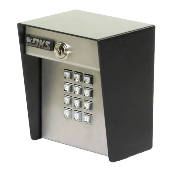
DKS 1503 Owner's Manual
Basic stand alone digital keypad entry devices
Hide thumbs
1
2
3
4
Table Of Contents
5
6
7
8
9
10
11
12
13
14
15
16
17
page
of
17
Go
/
17
Contents
Table of Contents
Bookmarks
Table of Contents
Table of Contents
Important Notices
Section 1 - Installation
Mounting Dimensions
Wiring
Wiring Diagram
Wire Diagram
Terminal Identification
Aiphone Intercom Station Connections
Section 2 - Programming
Master Code
Relay Strike Time
Programming Four-Digit Entry Codes
Erasing Four-Digit Entry Codes
Programming Five-Digit Entry Codes
Erasing Five-Digit Entry Codes
Programming Four-Digit Hold Codes
Erasing Four-Digit Hold Codes
Section 3 - Operating Instructions
Four-Digit Entry Codes
Four-Digit Hold Code
Five-Digit Entry Codes
Request to Exit
Advertisement
Quick Links
1
Wiring
2
Wiring Diagram
3
Programming Four-Digit Entry Codes
4
Master Code
5
Erasing Four-Digit Entry Codes
6
Section 2 - Programming
Download this manual
Owner's Manual
P/N 1503-065 REV E, 3/14
Copyright 2001 DoorKing, Inc. All rights reserved.
Basic Stand Alone Digital Keypad Entry Devices
Models 1503 and 1504
DoorKing, Inc.
120 Glasgow Avenue
Inglewood, California 90301
Phone: 310-645-0023
Fax: 310-641-1586
www.doorking.com
U.S.A.
Table of
Contents
Previous
Page
Next
Page
1
2
3
4
5
Advertisement
Table of Contents
Need help?
Do you have a question about the 1503 and is the answer not in the manual?
Ask a question
Questions and answers
Related Manuals for DKS 1503
Keypad DKS 1504 Owner's Manual
Basic stand alone digital keypad entry devices (17 pages)
This manual is also suitable for:
1504
Table of Contents
Save PDF
Print
Rename the bookmark
Delete bookmark?
Delete from my manuals?
Login
Sign In
OR
Sign in with Facebook
Sign in with Google
Upload manual
Upload from disk
Upload from URL


Need help?
Do you have a question about the 1503 and is the answer not in the manual?
Questions and answers