
Summary of Contents for Spirit Digital 328
- Page 1 3 3 2 2 8 8 SPIRIT DIGITAL SOFTWARE v 2 U U S S E E R R G G U U I I D D E E Spirit Digital 328 Users Guide Version 2...
- Page 2 3 3 2 2 8 8 SPIRIT DIGITAL Spirit Digital 328 Users Guide Version 2...
-
Page 3: Table Of Contents
S S A A F F E E T T Y Y G G U U I I D D E E Safety Symbol Guide Approvals and Notice Warranty Important Safety Instructions Cautions Warnings Spirit Digital 328 Users Guide Version 2... -
Page 4: Safety Symbol Guide
Must be followed carefully to avoid bodily injury. WARNINGS Must be observed to avoid damage to your equipment. NOTES Contain important information and useful tips on the operation of your equipment. i i i i Spirit Digital 328 Users Guide Version 2... - Page 5 3 3 2 2 8 8 SPIRIT DIGITAL IMPORTANT Please read this manual carefully before connecting your Interface to the mains for the first time. i i i i i i Spirit Digital 328 Users Guide Version 2...
-
Page 6: Warranty
3 3 2 2 8 8 SPIRIT DIGITAL WARRANTY Spirit and Soundcraft End User Dealer i i v v Spirit Digital 328 Users Guide Version 2... -
Page 7: Important Safety Instructions
The wire which is coloured Blue must be connected to the terminal in the plug which is marked with the letter N. The wire which is coloured Brown must be connected to the terminal in the plug which is marked with the letter L. Spirit Digital 328 Users Guide Version 2... -
Page 8: Warnings
3 3 2 2 8 8 SPIRIT DIGITAL WARNINGS v v i i Spirit Digital 328 Users Guide Version 2... - Page 9 Introducing the Spirit Digital 328 ....7 The Ins and Outs of the 328 ..... . 7 Section 2 Getting started straight out of the box .
- Page 10 Software Upgrade ..... .161 Upgrading Digital 328 Software ....162...
- Page 11 C Signal Flow Diagram ......188 D Digital 328 Expanded Surface Diagram ... . 189 E Cable Connection Diagrams .
-
Page 13: The User Guide
25 years experience in professional console design. The Spirit range gives you premier audio quality and features whatever your mixing needs. We hope you enjoy using your Spirit Digital 328 mixer as much as we have enjoyed designing it! - Page 14 3 3 2 2 8 8 SPIRIT DIGITAL Spirit Digital 328 Users Guide Version 2...
-
Page 15: Introducing The Spirit Digital 328
D D i i g g i i t t a a l l 3 3 2 2 8 8 In this Section: The Spirit Digital 328 Console Introducing the Spirit Digital 328 The Ins and Outs of the 328 Spirit Digital 328 Users Guide Version 2... -
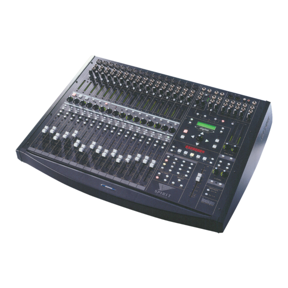
Page 16: The Spirit Digital 328 Console
3 3 2 2 8 8 SPIRIT DIGITAL THE SPIRIT DIGITAL 328 CONSOLE Spirit Digital 328 Users Guide Version 2... - Page 17 Stereo Input 1A - 1D and Stereo Input 2 Monitor Path Controls Dynamics Switch Main Output / Dynamics Gain Reduction Meters LCD Panel and LCD Mode Switches PARAM Encoder, Cursor Keys, EXIT/NO, ENTER/YES, UNDO and REDO Switches Spirit Digital 328 Users Guide Version 2...
- Page 18 Stereo Input 1 and 2 Control Timecode Display and Transport Controls FX Return 1 and 2 Control AUX/FX Pre/Post and Group/Channel Link Switches Solo Control Panel Snapshot Control Panel Select Panel for Channel Parameters Mix Fader Spirit Digital 328 Users Guide Version 2...
-
Page 19: Introducing The Spirit Digital 328
THE INS AND OUTS OF THE 328 Analogue Inputs The Spirit Digital 328 offers 16 Mic/Line inputs, using Spirit's highly acclaimed Ultra Mic Pre-amps. A Global Phantom Power, applying 48V to all 16 Microphone inputs, is accessed by pressing the PHANTOM POWER switch. -
Page 20: Digital Inputs
SPIRIT DIGITAL Digital Inputs The 16 digital input channels on the rear of the 328 are accessed by two 8 Channel TDIF or ADAT Optical input connectors. There is also a dedicated AES/EBU Input, and S/PDIF Input for connecting CD, Minidisc and DAT Machines. - Page 21 3 3 2 2 8 8 SPIRIT DIGITAL Metering The 328 has full metering of every input and output signal as standard - no need for an extra meter bridge here! The 10 segment bar graph meters have 3 easily selected modes that show either...
-
Page 22: Machine Control
RS422 or MIDI Note On/Note Off. Audio quality All analogue inputs and outputs on the 328 have the same crystal clear 24 bit 128 oversampling Analogue to Digital and Digital to Analogue (A/D and D/A) converters, ensuring wide dynamic range and superb sonic performance. - Page 23 Okay let's make some noise! Using the 'E-strip' for Equalisation, Panning, Aux sends and adding Effects Let's add some reverb Okay now for some Compression Storing the settings in the 'SNAPSHOT' memory locations 1 1 1 1 Spirit Digital 328 Users Guide Version 2...
-
Page 24: Getting Started Straight Out Of The Box
We will get a signal in on Channel 1, route it to the Mix outputs, add some EQ, and then add some Reverb and a Compressor, and finally store all the settings we have made as a 'Snapshot' 1 1 2 2 Spirit Digital 328 Users Guide Version 2... -
Page 25: Audio Hook-Up
(and are lucky enough to still people get this bit wrong!) and switch the 328 on. You will see very quickly that have the user manuals) every light on the mixer lights up briefly. Don't worry this is perfectly normal, and... -
Page 26: Adding Effects
Now that you have some audio running through the console, let's check out the E-Strip (See Section 3.B - for an in depth look at this unique 328 feature) “ When you press the 'SELECT' button on Channel 1 the E-Strip instantly becomes active for that channel. -
Page 27: Okay Now For Some Compression
OKAY NOW FOR SOME COMPRESSION The two high quality Dynamics Processors built into the 328 can be applied to the signal in the usual way i.e. by feeding the full signal to the input of the processor and returning the output back to the same channel. Let's do it! “... -
Page 28: Section
Digital 328 operates! Section 3 of this manual gives an in depth view of all of the functions available on the 328. Be prepared for a new audio experience. 1 1 6 6 Spirit Digital 328 Users Guide Version 2... -
Page 29: The Inputs And Outputs
3C - The SELECT panels 3D - Stereo Inputs 3E - FX Returns 3F - Solo Control 3G - Snapshots 3H - Group/Aux/FX 3I - Transport Controls 3J - Master section 1 1 7 7 Spirit Digital 328 Users Guide Version 2... - Page 30 3 3 2 2 8 8 SPIRIT DIGITAL 1 1 8 8 Spirit Digital 328 Users Guide Version 2...
- Page 31 O O u u t t p p u u t t s s In this Section: Part 1 - The Front Panel Inputs and Outputs Part 2 - The Rear panel Inputs and Outputs 1 1 9 9 Spirit Digital 328 Users Guide Version 2...
- Page 32 OUTPUTS Mic/Line Inputs 1-16 The 16 analogue inputs on the 328 comprise of a Microphone input, Line input, Insert point, Trim control and High Pass Filter (HPF) After the High Pass Filter, 24 bit A/D conversion takes place and from here on the signal is handled entirely in the digital domain until it reaches one of the analogue output stages.
-
Page 33: Mic Input
Power switched on if Compressors, Gates or Equalisers for additional signal processing. For the correct correctly balanced cables method of making up insert cables for use with the 328 please consult Appendix E are used. Ensure that of this manual. - Page 34 MIDI MACHINE CONTROL (MMC). External recording devices can be put into mixing console, read record from the front panel of the 328. The current status of the recording through Section 2 devices tracks (1-16) can be monitored using these LED as follows:...
-
Page 35: Monitor Section
3 3 2 2 8 8 SPIRIT DIGITAL Monitor Section The Monitor section of the 328 is where you will connect your studio monitor speakers, headphones and mix down machines. You can also select in the Monitor section what source signal you will be listening to in your studio monitor speakers. - Page 36 When this button is pressed the control room output is muted. The PHONES output is unaffected. PHONES This control adjusts the level sent to the stereo PHONES output. C/RM This control adjusts the level sent to the C/RM (Control Room) output. 2 2 4 4 Spirit Digital 328 Users Guide Version 2...
- Page 37 Two 16 segment Peak reading Bargraph Meters normally display the Mix L/R output level. Pressing the DYNAMICS button on the left of the meters switches the meters to read either Gain Reduction (Compressor/Limiters) or Gate Open/Close (Gates /Expanders). 2 2 5 5 Spirit Digital 328 Users Guide Version 2...
- Page 38 OUTPUTS 8 TRK A (17-24) The 8 TRK A section on the rear of the 328 is an 8-channel bi-directional Digital I/O interface for connecting to recording devices or expansion boxes. There are two types of Digital I/O formats supported namely Tascam TDIF and ADAT Optical.
- Page 39 SPIRIT DIGITAL 8 TRK B (25-32) The 8 TRK B section on the rear of the 328 is an 8-channel bi-directional Digital I/O interface for connecting to recording devices or expansion boxes. There are two types of Digital I/O formats supported namely Tascam TDIF and ADAT Optical.
- Page 40 MENU to any of the following: - STE 1, STE 2, FX return 1, FX return 2, 2TRK. (See Section 3J - Part 5.9 'SPDIF Input Setup' for setup information) 2 2 8 8 Spirit Digital 328 Users Guide Version 2...
-
Page 41: Automation Techniques
These BNC connectors are for synchronizing external devices to the 328's own internal Wordclock, or for synchronizing the 328 to an external Wordclock source. If you would like to know The 328 can be selected via the MENU to be either the Wordclock Master or more about Wordclock Slave. - Page 42 TIMECODE IN This connector is for connecting external SMPTE Timecode sources. The 328's SNAPSHOT memories can be programmed to respond to incoming SMPTE Timecode, and the Timecode can be displayed on the 328's own Timecode display window. MAINS SUPPLY CONNECTOR...
- Page 43 In this Section: Overview Part 1 - The E-Strip as a Channel strip Part 2 - The E-Strip as a Row of Controllers Part 3 - The FADER and METER BANKS 3 3 1 1 Spirit Digital 328 Users Guide Version 2...
- Page 44 SPIRIT DIGITAL OVERVIEW The E-Strip is the heart of 328 operation. The E-Strip will make the 328 feel very like an analogue console when you use it, and we are sure you will come to love it as much as we do!
- Page 45 Rotating the LF, MID or HF encoder knob in a clock wise direction will sweep the frequencies from the lowest value through to the highest value in each frequency band e.g. 40Hz to 800Hz for the LF band. 3 3 3 3 Spirit Digital 328 Users Guide Version 2...
-
Page 46: Auxiliary Sends
(illuminated) and AUX 3&4 set to POST FADE (not illuminated). pressed the LCD display will show the level of both FX 1 and FX 2 with a range from -60dB through to 0dB. 3 3 4 4 Spirit Digital 328 Users Guide Version 2... - Page 47 The PAN encoder knob sets the amount of the channel feeding the left and right across the stereo image. MIX busses or linked (stereo) Groups allowing a signal to be moved smoothly across the stereo image. 3 3 5 5 Spirit Digital 328 Users Guide Version 2...
- Page 48 The 16 ROTARY CONTROLS can be configured for use as level controls for either the TAPE 17-32 inputs or the MIC/LINE 1-16 inputs. This allows immediate access to all 32 inputs on the 328 and is useful in both recording and live applications.
- Page 49 By selecting any one of the AUX 1, 2, 3 or 4 buttons in the ROTARY CONTROLS section, the ROTARY CONTROLS will now function as AUX sends for TAPE channels 17-32 according to the number of the AUX selected. 3 3 7 7 Spirit Digital 328 Users Guide Version 2...
- Page 50 The green ring of LEDs surrounding the ROTARY CONTROLS will represent the audio send level. The LCD can be put into SELECT mode to view precise values for any level adjustments (see Section 3J Part 1). 3 3 8 8 Spirit Digital 328 Users Guide Version 2...
-
Page 51: Pan Controls
PAN position of the channel within the stereo image. The LCD can be put into SELECT mode to view precise values for any pan adjustments (see Section 3J Part 1). 3 3 9 9 Spirit Digital 328 Users Guide Version 2... - Page 52 16 ROTARY ENCODERS, the 16 MUTE and the 16 SOLO switches can be used as 64 user programmable MIDI controllers (see Section 3J Part 5.3) . 4 4 0 0 Spirit Digital 328 Users Guide Version 2...
- Page 53 Bargraph meters 10-13 Show the Master send level of AUX sends 1-4 “ Bargraph meters 14-15 Show the Master send level of FX sends 1-2 “ Bargraph meters 16 Not used. 4 4 1 1 Spirit Digital 328 Users Guide Version 2...
- Page 54 3 3 2 2 8 8 SPIRIT DIGITAL 4 4 2 2 Spirit Digital 328 Users Guide Version 2...
- Page 55 PHASE button T.SND DIR button EQ IN button SIP SAFE button ROUTE TO MIX button REC ARM button MUTE button SOLO button ROUTE TO GROUP 1-8 buttons Query Mode 4 4 3 3 Spirit Digital 328 Users Guide Version 2...
- Page 56 SPIRIT DIGITAL OVERVIEW The SELECT panel on the 328 is where you will find the rest of the controls you would expect to find on an analogue mixer such as the Group Routing buttons, Phase Reverse, EQ In/Out etc. When a channel SELECT button is pressed the E-Strip and the select panel work together.
- Page 57 For example let's assume we have two ADATs connected to the 8 TRK A and 8 TRK B optical connectors in order to perform a live 16-track recording. The 328 has 8 group outputs which would not allow us to record all 16 channels simultaneously.
- Page 58 REC ARM. The REC LED above the chosen Channel number will flash. When the remote recording device is put into record either directly or from the 328 Transport Controls, the REC ARM LED will remain illuminated.
- Page 59 Channels may be routed to individual GROUPS (mono) or to pairs of GROUPS that have been Stereo linked as odd/even pairs allowing for panning across the GROUP outputs. (See Section 3H - Group/Aux/ FX for more details) 4 4 7 7 Spirit Digital 328 Users Guide Version 2...
- Page 60 AUX PRE/POST EQ IN MUTE CHANNEL/GROUP LINK SIP SAFE SOLO By pressing and holding any of the above switches, the state of the console can be quickly seen and altered. 4 4 8 8 Spirit Digital 328 Users Guide Version 2...
- Page 61 S S t t e e r r e e o o I I n n p p u u t t s s In this Section: Overview STE-1 and STE-2 ROTARY CONTROLS SELECT button MUTE button SOLO button 4 4 9 9 Spirit Digital 328 Users Guide Version 2...
- Page 62 SPIRIT DIGITAL OVERVIEW The 328 has two dedicated stereo inputs namely STE 1 and STE 2. While STE 2 is a single stereo input, STE 1 enables 4 balanced analogue stereo inputs to be submixed in the analogue domain and fed into 1 digital signal path. This makes STE 1 input suitable for the returns from FX units connected to the Digital 328's 4 auxiliary outputs.
- Page 63 SOLO BUTTON The SOLO button places the selected STE-1or STE-2 input into solo mode. The solo status will follow the selection that has been made in the SOLO CONTROL panel. 5 5 1 1 Spirit Digital 328 Users Guide Version 2...
- Page 64 3 3 2 2 8 8 SPIRIT DIGITAL 5 5 2 2 Spirit Digital 328 Users Guide Version 2...
- Page 65 F F X X R R E E T T U U R R N N S S In this Section: Overview FX-1 and FX-2 ROTARY CONTROLS SELECT buttons 5 5 3 3 Spirit Digital 328 Users Guide Version 2...
- Page 66 Stereo inputs have. Instead the switches in the SELECT panel must be used. The Digital 328 internal FX returns are not routable to the Group outputs. Note: The T.SND DIR, REC ARM, PHASE and ROUTE TO GROUP buttons in the SELECT panel do not function when the SELECT panel is active for either FX-1 or FX-2.
- Page 67 S S O O L L O O C C O O N N T T R R O O L L In this Section: Overview SIP button AFL button PFL button CLEAR button 5 5 5 5 Spirit Digital 328 Users Guide Version 2...
- Page 68 When any SOLO button is pressed the CLEAR button will illuminate to show that currently selected. there is a SOLO active somewhere on the 328. Pressing the CLEAR button will clear any selected SOLO. (No surprises here then!) 5 5 6 6...
- Page 69 3 3 G G S S N N A A P P S S H H O O T T S S In this Section: Overview NEXT button RECALL button STORE button 5 5 7 7 Spirit Digital 328 Users Guide Version 2...
- Page 70 The displayed Timecode reference is always stored with the snapshot. Note: Please refer to Section 3J Part 2 for an in depth look at SNAPSHOTS and how they work. 5 5 8 8 Spirit Digital 328 Users Guide Version 2...
- Page 71 G G R R O O U U P P / / A A U U X X / / F F X X In this Section: AUX/FX PRE button GROUP LINK button 5 5 9 9 Spirit Digital 328 Users Guide Version 2...
- Page 72 Note: You can only link adjacent 'odd' and 'even' numbered Groups together i.e. Group 1and 2, 3 and 4, 5 and 6, 7 and 8 not Group 2 and 3, 4 and 5, 6 and 7. 6 6 0 0 Spirit Digital 328 Users Guide Version 2...
- Page 73 Channel 15 or 16 whilst holding down the GROUP LINK button. Note: You can only link adjacent 'ODD' and 'EVEN' numbered Channels together, for example - Channel 1 & 2, 3 & 4, 5 & 6 etc. 6 6 1 1 Spirit Digital 328 Users Guide Version 2...
- Page 74 3 3 2 2 8 8 SPIRIT DIGITAL 6 6 2 2 Spirit Digital 328 Users Guide Version 2...
- Page 75 In this Section: Overview Timecode Display STO 1 button STO 2 button PLAY button STOP button FAST FORWARD button REWIND button RECORD button LOC 1 button LOC 2 button 6 6 3 3 Spirit Digital 328 Users Guide Version 2...
- Page 76 SPIRIT DIGITAL OVERVIEW The TRANSPORT CONTROL panel is used in conjunction with the TAPE MACHINE SETUP page found in the 328's MENU section (See Section 3J Part 5.13). When the LCD is in The buttons found in the TRANSPORT CONTROL panel can be used for...
- Page 77 The PLAY button will start playback of an external device connected via the MIDI or RS422 ports, or it can be used to start playback of the 328's own internal Timecode when acting as a timecode master device, as configured in the TAPE MACH SETUP page in the MENU section (see Section 3J Part 5.13).
- Page 78 Out and RS 422 ports to a connected recording device requesting it to locate to the assigned Timecode Address (see Section 3J Part 5.13). The Timecode Display will also indicate the LOC 2 Timecode address. 6 6 6 6 Spirit Digital 328 Users Guide Version 2...
- Page 79 Part 1 - The SELECT button and it's applications Part 2 - The SNAPSHOT button Part 3 - Lexicon FX processors Part 4 - Dynamics processors Part 5 - The ‘MENU’ button 6 6 7 7 Spirit Digital 328 Users Guide Version 2...
-
Page 80: Overview
The Master Section contains a LCD display, and the only Menus required for operating the 328 (other than those from your nearest Take Away food vendor!) The Menus are used mainly for setup and library purposes only so don't get... - Page 81 “ Make sure that TAPE 17-32 is selected in the FADER BANK (this will give us access to Channel 26) “ Press the Channel SELECT button for TAPE 26 in the SELECT panel, this will assign the 'E-Strip' to Channel 26. 6 6 9 9 Spirit Digital 328 Users Guide Version 2...
-
Page 82: Channel Naming
While in the SELECT mode individual channels can be renamed for storing as part of a USER SETUP . This is useful for remembering how different sources where connected to the 328 in the absence of a track sheet! The following channels can be renamed - MIC/LINE 1-16, TAPE 17-32, STE 1and 2, FX RTN 1 and 2. -
Page 83: Part 2 - The Snapshot Button
USING SNAPSHOTS Being able to store SNAPSHOTS of all of the 328 settings (except the TRIM and HPF settings as these are found in the analogue side of the mixer) is very useful for both recording and live sound applications. -
Page 84: Storing Snapshots
SNAPSHOT memories and recalled simply by using the NEXT button. For festivals, each band could be sound checked and all individual settings stored in the 328 for later recall - no more pieces of paper with setup information scribbled on them and no time to reset the desk! These are just a couple of the many different applications for using SNAPSHOT recall. -
Page 85: Naming A Snapshot
“ To delete the selected character and move the cursor one character to the left, press and hold the cursor key and press the cursor key once for each character to be deleted 7 7 3 3 Spirit Digital 328 Users Guide Version 2... - Page 86 “ You may now use the PARAM encoder to set the MIDI Recall function ON or OFF. “ When you are finished, press the ENTER key to store the MIDI Recall setting. 7 7 4 4 Spirit Digital 328 Users Guide Version 2...
- Page 87 EXIT/NO to cancel. DELETING SNAPSHOTS If your 328 has no <EMPTY> SNAPSHOT memories left, you can either over write existing memories (if they are not WRITE PROTECTED) or clear them. “ Select the SNAPSHOT you want to delete by using the arrow keys or the PARAM encoder.
-
Page 88: Part 3 - Lexicon Fx Processors
PART 3 - LEXICON FX PROCESSORS Overview The 328 includes two superb sounding Lexicon FX Processors which include various different FX including Hall Reverbs, Plate Reverbs, Flanger, Multi Tap Delay, Resonator, Inverse Reverb, Gate and Chorus. These FX processors can make a huge difference to the sound of your mixes and are essential for getting a professional sounding result. - Page 89 You can still adjust the parameters of the Factory Presets if you want to fine tune the effect for your own mix. 7 7 7 7 Spirit Digital 328 Users Guide Version 2...
- Page 90 1 output level on the FX 1meter. Now turn the FX 1 ROTARY CONTROL on the selected Channel and you should see signal appearing on the FX 1 output meter. 7 7 8 8 Spirit Digital 328 Users Guide Version 2...
- Page 91 FX Settings menu, which the LCD displays immediately. Use the arrow keys to select the parameter you want to adjust, and the PARAM encoder to adjust the chosen parameter. 7 7 9 9 Spirit Digital 328 Users Guide Version 2...
- Page 92 The LCD display will now show <FX Algorithm> and one of the following default effects - Hall Reverb, Plate Reverb, Flanger, Multi Tap Delay, Resonator, Inverse Reverb, Gate and Chorus. 8 8 0 0 Spirit Digital 328 Users Guide Version 2...
- Page 93 The LCD will prompt to confirm the delete. Press the ENTER/YES key to confirm the delete or press the EXIT/NO key to abort. The LCD will return to displaying the list of stored User FX Presets. 8 8 1 1 Spirit Digital 328 Users Guide Version 2...
-
Page 94: Part 4 - Dynamics Processors
Think of them as the 'Swiss Army Knife' section of the 328, if there's a problem on a signal regarding level or noise, this is where you go to try to sort it out. - Page 95 Let's take a more detailed look at the parameters found in the 328's Gate. SCH (Source Channel or Side Chain) SCH determines which channel will be routed ('patched') into the Gate.
- Page 96 The Compressor has a Threshold setting which determines what level the signal has to reach before the Compressor starts to reduce the level. Let's take a closer look at the 328's Compressor. SCH (Source Channel or Side Chain) SCH determines which mono or stereo signal will be routed ('patched') into the Compressor.
- Page 97 The Makeup control can also be used to attenuate the signal if required. The Makeup control has a range of -12dB to +12dB. 8 8 5 5 Spirit Digital 328 Users Guide Version 2...
- Page 98 The parameters available are identical to those found in the Limiter and Gate algorithms. USING THE DYNAMICS PROCESSORS The Dynamics Processors found on the 328 are very useful for both corrective and creative purposes. The following section describes how to apply the Dynamics Processors to signals.
-
Page 99: Assigning The Dynamics Processors
ENTER/YES and use the st arrow keys or PARAM encoder to set the required algorithm and press ENTER/YES again to confirm. Use the arrow keys to select the SCH: Channel # XX parameter. 8 8 7 7 Spirit Digital 328 Users Guide Version 2... - Page 100 The LCD display will read and the library number will be displayed below this. You can now use the arrow keys or the PARAM encoder to select a library number (1 - 64). 8 8 8 8 Spirit Digital 328 Users Guide Version 2...
- Page 101 It will flash to show that it is ready for editing. Press the EXIT/NO button and the LCD display will show and the chosen Preset. Press ENTER/YES to delete or EXIT/NO to abort. 8 8 9 9 Spirit Digital 328 Users Guide Version 2...
- Page 102 SPIRIT DIGITAL PART 5 - THE ‘MENU' BUTTON Overview The Digital 328 menu pages allow configuration of Digital I/O, MIDI setup, Snapshots and User Setups. There are 19 Menu pages, accessed by pressing the MENU switch: Software Info User Options...
-
Page 103: Software Info
ENTER/YES button to enter the chosen page. SOFTWARE INFO This page will tell you what software version your 328 is currently operating on. The functions described in this User Guide are based on consoles using Version 2.0 Software or later. -
Page 104: User Options
Set OMNI mode to ON if you wish the 328 to respond to incoming MIDI Program Changes on all 16 MIDI channels or to OFF if you wish the 328 to respond only to the MIDI channel selected above. Note that MIDI Program... - Page 105 When requesting data dumps from a remote source with MIDI System Exclusive messages, the 328 device ID must be set correctly. By default this is set to ID 1 and for most purposes is best left at this value. If you use linked consoles, the device IDs should be set differently so that the remote device is able to send System Exclusive commands to each desk individually.
- Page 106 382 (labeled DA88/V4). The setting of 380 (DA88/OLD) must be used for Tascam DA88 machines with a system board of version 1-3. “ Osc Src The 328 has an in built Oscillator which can be assigned to a number of different destinations for calibration purposes. 9 9 4 4...
-
Page 107: Midi Controllers
Controllers 1-16 are the 16 Faders, controllers 17-32 are the 16 rotary encoders along the E-Strip, controllers 33-48 are the 16 Solo switches and controllers 49-64 are the 16 Mute switches. 9 9 5 5 Spirit Digital 328 Users Guide Version 2... - Page 108 “ To delete the selected character and move the cursor one character to the left, press and hold the cursor key and press the cursor key once for each character to be deleted 9 9 6 6 Spirit Digital 328 Users Guide Version 2...
-
Page 109: Midi Ctl Presets
Two types of MIDI dump can be made from the 328. Stored Snapshots, User Setups and all Presets can be dumped from the 328 MIDI Out port as MIDI System Exclusive data to be recorded and stored externally on a MIDI data filer or MIDI sequencer package. - Page 110 Use the PARAM encoder to scroll through the different dumping choices. ALL DATA Executing this dump will transmit all data currently stored within the 328 as System Exclusive data from the 328 MIDI Out port. Select the All Data dump and press ENTER/YES to start the dumping process.
- Page 111 All stored Lexicon FX Presets can be dumped as System Exclusive data from the MIDI Out port. Executing this dump will transmit all FX Presets currently stored within the 328 as System Exclusive data from the 328 MIDI Out port. All Preset locations are stored within the dump so that dumping the data back to the console will restore the FX Presets to their original location.
- Page 112 Executing this dump will transmit all MIDI Controller Presets currently stored within the 328 as System Exclusive data from the 328 MIDI Out port. All Preset locations are stored within the dump so that dumping the data back to the console will restore the FX Presets to their original location.
- Page 113 MIDI Continuous Controller values to be recorded into a sequencer or to synchronize a connected MIDI device. Select the Controllers dump with the PARAM encoder and press ENTER/YES to start the dump. The Controllers dump cannot be aborted. 1 1 0 0 1 1 Spirit Digital 328 Users Guide Version 2...
-
Page 114: Midi Dump In
All of the Digital 328s automatable parameters can be transmitted as a string of MIDI Continuous Controller values. This dump is particularly useful to make at the beginning of a 328 automation track within a MIDI sequencer. It has the same effect as transmitting a MIDI Program Change to the console to recall a Snapshot, synchronizing the 328 with the beginning of the track. -
Page 115: Tape Trim Setup
INDIVIDUAL ADJUSTMENT Press the ENTER/YES button to enter the Tape Trim Setup page The LCD display will show: Both the ENTER/YES and the EXIT/NO buttons will flash. 1 1 0 0 3 3 Spirit Digital 328 Users Guide Version 2... -
Page 116: Tape Port Select
TAPE PORT SELECT The 328 has two sets of digital Tape inputs and outputs on it's back panel - 8 TRK A (TAPE 17-24) and 8 TRK B (TAPE 25-32). Both ADAT and TDIF outputs for 8 TRK A and 8 TRK B are permanently active, Pressing the but each 8 Track input can only be active for either TDIF or ADAT. - Page 117 ADAT/TDIF select page. If ADAT is selected this page is not available). The Sample Rate Flag must be set to the same Sample Rate at which the 328 is operat- ing, whether on Internal or External clock. To check this setting enter the Clock Source Sel menu (see Section 3J Part 5.14).
-
Page 118: Spdif I/P Setup
Use the PARAM encoder to select between: “ Aux/Mix The 328's 4 Aux sends, 2 FX sends and Mix L, R will be sent to the Aux Optical output for connecting to external equipment that uses ADAT Optical inputs. The channels are mapped in the following way: “... - Page 119 Press EXIT/NO to return to the main menu once you have made your choice. 5.10 AES/EBU I/P SETUP The AES/EBU digital stereo input on the back of the 328 can be routed to a number of different destinations. Press the ENTER/YES button to enter the AES/EBU I/P setup page Use the PARAM encoder to select one of the following destinations: “...
-
Page 120: Spdif O/P Setup
Press EXIT/NO to return to the main menu once you have made your choice. 5.11 SPDIF O/P SETUP The S/PDIF digital stereo output on the back of the 328 can derive its signal from a number of different sources. Press the ENTER/YES button to enter the SPDIF O/P page. - Page 121 The Sample Rate Flag must be set to the same sample rate at which the 328 is operating. The options are 32kHz, 44.1kHz, 48kHz and UNDF (Undefined). If the 328 is set to synchronize to external wordclock at a frequency of 48kHz, you must set the S/PDIF Output Sample Rate Flag to 48kHz.
- Page 122 3J part 5.14), the Status bits should remain at the default setting of AUTO. If the 328 is set to slave to an external wordclock source, you should check that the AES/EBU output stream Status Bits are set correctly. To set the flags manually, select Status Bits: MAN with the PARAM encoder.
-
Page 123: Tape Mach Setup
3 3 2 2 8 8 SPIRIT DIGITAL The Sample Rate Flag must be set to the same sample rate at which the 328 is operating. The options are 32kHz, 44.1kHz, 48kHz and UNDF (Undefined). If the 328 is set to synchronize to external wordclock at a frequency of 48kHz, you must set the AES/EBU Output Sample Rate Flag to 48kHz. - Page 124 328 to generate MIDI Timecode, set the Status to MASTER with the PARAM encoder. If you wish the 328 to slave to incoming LTC or MTC as defined in the Timecode Source menu (see above), set the Timecode Status menu to SLAVE with the PARAM encoder.
- Page 125 MIDI Note On commands. If your external device is set to receive MMC commands, use the PARAM encoder to select MMC. If you are using the 328 in conjunction with a computer based software sequencer package that will respond to MIDI Note On transport messages, Note On can be selected with the PARAM encoder.
- Page 126 In addition, the LOCATE 1 and LOCATE 2 switches can be assigned a predefined MIDI System Exclusive string particular to Digidesign ProTools, enabling remote selection between ProTools windows. Consult the downloadable 328 V2 ProTools guide for further information. The ninth MIDI Note On menu selects the MIDI channel on which the MIDI Note On messages are to be transmitted.
- Page 127 Press the EXIT/NO to return to the main Tape Mach Setup menu MMC CLOSED LOOP To configure the 328 for use with a standard MMC capable device, MMC Closed Loop should be selected as the Tape Machine Type. The console automatically acts as a Timecode Slave device, but transmits MMC commands to the Timecode Master device.
- Page 128 TIMECODE SOURCE When configured as a Timecode Slave, the 328 timecode display can show either MTC (MIDI Timecode) received at the MIDI In port or LTC/SMPTE received at the SMPTE In port. If your external device offers a MTC or LTC output, connect the correct cables and set the menu accordingly with the PARAM encoder.
- Page 129 Press the EXIT/NO to return to the main Tape Mach Setup menu ALESIS AI-2 The Transport Control section of the 328 can be used to control the transport of an Alesis ADAT in conjunction with the Alesis AI-2 synchronizer which provides the MIDI Interface for the ADAT allowing it to receive MMC commands from the 328.
- Page 130 TASCAM DTRS adjacent channels to make a stereo pair, it is The Transport Control section of the 328 can be used to control the transport of a preferable to leave the Tascam DA7HR, DA88, DA98 or DA98HR DTRS machine. 'Pan & Phase' setting to the default state of OFF Press the ENTER/YES button to enter the Tascam DTRS setup page.
- Page 131 SPIRIT DIGITAL FOSTEX G SERIES The Transport Control section of the 328 can be used to control the transport of a Fostex G16 or G24 tape machine in conjunction with the appropriate MMC interface, which provides the MIDI Interface for the G16 or G24 allowing it to receive MMC commands from the 328.
- Page 132 SPIRIT DIGITAL SONY 9 PIN The Transport Control section of the 328 can be used to control the transport of machines conforming to the Sony 9 Pin (RS 422) protocol. Press the ENTER/YES button to enter the Sony 9 Pin setup page.
- Page 133 Press the arrow key to set the default clock setting. If the 328 is set to slave to an External clock source, and wordclock is lost, a warning message indicating this will be displayed on the LCD. The 328 will revert to Internal clock, but in order to try to limit problems caused as a result of the loss, the sample frequency to which the console will revert can be set here.
-
Page 134: Snapshot Setup
SPIRIT DIGITAL Note that a DA88 version 4 model CANNOT be used with TDIF connections to the 328 simultaneously with a DA88 version 1, 2 or 3. You should contact your TEAC or Tascam distributor if you wish to upgrade the older machine. - Page 135 Section 3G for more information about assigning Timecode addresses to Snapshots. In this way, incoming Timecode from a Tape Machine can trigger the recall of Snapshots stored within the 328, enabling Timecode Snapshot automation. If 'OFF' is selected then Snapshots with pre-programmed Timecode addresses will not be recalled against incoming Timecode.
-
Page 136: Automation Setup
When in CONTROLLER automation mode, automation of all 'internal' parameters is disabled and the user definable MIDI Controller Bank becomes an automatable surface. This mode can be used if you wish to configure the 328's MIDI Controller Bank to be an automatable control surface for a sequencer package. - Page 137 Use the PARAM encoder to select the different modes. READ ONLY In READ ONLY mode the 328 will respond to incoming automation data being sent from a MIDI recording device, but will not transmit any automation data from the MIDI Out port.
- Page 138 When the LCD is in SELECT mode, pressing cursor keys simultaneously will toggle the automation Select CONTROLLER mode if you wish to disable automation of 328 'internal' mode between READ controls and enable automation of the MIDI Controller Bank. ONLY and READ/WRITE. As 328...
- Page 139 (default ON) “ Link Routing : ON/OFF Routing selection is linked (default ON) “ Pan & Phase: ON/OFF Pan position and phase is linked (default OFF) 1 1 2 2 7 7 Spirit Digital 328 Users Guide Version 2...
-
Page 140: User Setups
5.19 USER SETUPS The 328 has 27 User Setup memory locations. A User Setup is similar to a Snapshot in that it stores console parameters, although the User Setup will store the majority of menu settings also. Recall of a User Setup will therefore restore all aspects of the console at the point it was stored, including wordclock and Tape Port configuration. - Page 141 Snapshots, Presets or User Setups. Recalling the Factory Default settings in this way is identical to the soft reset on booting (see Section 2). 1 1 2 2 9 9 Spirit Digital 328 Users Guide Version 2...
- Page 142 “ To delete the selected character and move the cursor one character to the left, press and hold the cursor key and press the cursor key once for each character to be deleted 1 1 3 3 0 0 Spirit Digital 328 Users Guide Version 2...
-
Page 143: Display Setup
“ Use the PARAM encoder to set MIDI Recall to ON or OFF 5.20 DISPLAY SETUP The 328's LCD Contrast and LED Brightness can be altered by accessing 'hidden' Display Setup menu pages. To make adjustments to the LCD Contrast and/or the LED Brightness, press the cursor keys simultaneously while the top level MENU pages are active in the LCD display. - Page 144 (full). All LEDs on the console, including the illuminated switches are affected. “ Press EXIT/NO to return to the main Menu pages. These settings are stored within a User Setup. 1 1 3 3 2 2 Spirit Digital 328 Users Guide Version 2...
-
Page 145: Part 1 - Digital 328 Snapshot And Dynamic Automation
T T e e c c h h n n i i q q u u e e s s In this Section: Part 1 - Digital 328 Snapshot and Dynamic Automation Part 2 - Quick Start Guides 1 1 3 3 3 3... -
Page 146: Dynamic Automation
Each Snapshot can be allocated a Timecode Address. For details on the different ways in which this can be done, see Section 3J Part 2. When the Digital 328 is configured to receive incoming Timecode or is generating timecode internally, the console can be set to recall Snapshots with an assigned Timecode Address. - Page 147 MIDI Program Change information. Connect the Digital 328 MIDI Out to the MIDI In of the sequencer, set a Digital 328 MIDI track to record and manually recall the Snapshots as the track passes. On replay of the track, the MIDI Program Changes will be retransmitted to the Digital 328, remotely recalling the Snapshots.
- Page 148 MIDI sequencer. When a Read mode is selected in the Automation Setup menu, reception of relevant Continuous Controller values at the MIDI In port will instruct the Digital 328 to automate the corresponding parameter accordingly.
- Page 149 FURTHER AUTOMATION TIPS You must ensure that MIDI Thru is disabled for at least the Digital 328 MIDI port within your sequencer. Unlike MIDI synthesisers, the console cannot be put into a Local Off mode due to the way in which the motorised faders adjust the audio levels directly within the console.
-
Page 150: Quick Start Guides
For the configurations below, it is assumed that you have a working knowledge of Logic Audio for Mac or PC. AUTOMATING THE DIGITAL 328 WITH LOGIC AUDIO Firstly ensure that Digital 328 MIDI Dynauto is set to ON and that the console is in READ/WRITE automation mode. LAUNCH LOGIC AUDIO Open the Options | Settings | MIDI Settings window and set the 'Instrument with no MIDI Thru function' to Digital 328. - Page 151 Open the Environment window and create a new 328 layer. On this layer create a new Instrument. In the Object Parameters window, label the new instrument 'Digital 328', set the MIDI Out port correctly and set it to transmit on all MIDI channels.
- Page 152 For the configurations below, it is assumed that you have a working knowledge of Cubase VST. AUTOMATING THE DIGITAL 328 WITH CUBASE VST Firstly ensure that Digital 328 MIDI Dynauto is set to ON and that the console is in READ/WRITE automation mode. Launch Cubase VST.
-
Page 153: Linked Consoles
Go to Options | Midi Setup | System and uncheck the MIDI Thru Enabled box. In the Track Inspector set the track output to the Digital 328 MIDI Port, and set the track to output on "any" MIDI Channel. This method will ensure the data recorded is sent out on the correct channel. - Page 154 Digital Performer, FreeMIDI, and the Macintosh environment. AUTOMATING THE DIGITAL 328 WITH DIGITAL PERFORMER Verify that Digital 328 MIDI Dynauto is set to ON and that the console is in READ/WRITE automation mode. Also make sure that MIDI In and Out connections are made between the 328 and a MIDI interface.
- Page 155 Digital 328 website. TRANSMITTING MIDI TIMECODE TO THE DIGITAL 328 Ensure that the 328 is set to respond to incoming MIDI Timecode (see Section 3J Part 5.13). Under the Basics Menu in Digital Performer, select 'Transmit Sync'. MIDI Time Code will now be routed to the Digital 328.
- Page 156 For the configurations below, it is assumed that you have a working knowledge of Cakewalk Pro Audio 9. AUTOMATING THE DIGITAL 328 WITH CAKEWALK PRO AUDIO Firstly ensure that Digital 328 MIDI Dynauto is set to ON and that the console is in READ/WRITE automation mode. Launch Cakewalk Pro Audio.
- Page 157 Name the second device "Unused 328" and select the same properties as above. You will need to create this unused device even if you do not have a second 328. For more details, download the Pro Tools setup guide from our website.
- Page 158 Download the Pro Tools MIDI Controller Preset for the 328 from the Digital 328 website. Dump the file into the 328 according to the attached instructions - or set the Digital 328 MIDI Controllers as follows (see Section 3J Part 5.3) Next, in Pro Tools, go to the Setups | Peripherals | MIDI Controllers Menu.
- Page 159 Part 5.13). Under the Session Setup Window in Pro Tools, check 'MTC To Port' and select the Digital 328 as the device. MIDI Time Code will now be routed to the Digital 328. 1 1 4 4 7 7 Spirit Digital 328 Users Guide Version 2...
- Page 160 “ 'Open Loop', in which the 328 MIDI Controller bank controls the first 16 Faders and Pan controls within the Soundscape mixer “ 'Closed Loop' in which the 328 both controls and is controlled by the 16 Faders, Pan controls, Solo and Mute switches within the Soundscape mixer For the configurations below, it is assumed that you have a working knowledge of the Soundscape editing software and Console Manager.
- Page 161 3 3 2 2 8 8 SPIRIT DIGITAL When using the Digital 328 Open Loop Interface, the faders and pan pots of the Soundscape mixer will appear red until the 328 fader/encoder passes through the value to which they are set. Once the 328 MIDI fader/encoder has passed through this value, the Console Manager object will follow the 328 control.
- Page 162 3 3 2 2 8 8 SPIRIT DIGITAL 1 1 5 5 0 0 Spirit Digital 328 Users Guide Version 2...
Need help?
Do you have a question about the 328 and is the answer not in the manual?
Questions and answers