Table of Contents
Advertisement
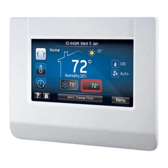
INSTALLATION MANUAL
TOUCH SCREEN COMMUNICATING CONTROL
MODELS: S1-TTSCC01
GENERAL . . . . . . . . . . . . . . . . . . . . . . . . . . . . . . . . . . . . . . . . . . . . . . . . . . . . . . . . . . . . . . . . . . . 2
SAFETY CONSIDERATIONS . . . . . . . . . . . . . . . . . . . . . . . . . . . . . . . . . . . . . . . . . . . . . . . . . . . . 2
INSPECTION . . . . . . . . . . . . . . . . . . . . . . . . . . . . . . . . . . . . . . . . . . . . . . . . . . . . . . . . . . . . . . 2
LIMITATIONS . . . . . . . . . . . . . . . . . . . . . . . . . . . . . . . . . . . . . . . . . . . . . . . . . . . . . . . . . . . . . . 2
INSTALLATION . . . . . . . . . . . . . . . . . . . . . . . . . . . . . . . . . . . . . . . . . . . . . . . . . . . . . . . . . . . . . . . 3
LOCATION . . . . . . . . . . . . . . . . . . . . . . . . . . . . . . . . . . . . . . . . . . . . . . . . . . . . . . . . . . . . . . . . 3
MOUNTING THE TOUCH SCREEN COMMUNICATING CONTROL . . . . . . . . . . . . . . . . . . . 4
REMOVING CONTROL MOUNTING BACK PLATE . . . . . . . . . . . . . . . . . . . . . . . . . . . . . . . . 5
WIRING COMMUNICATION . . . . . . . . . . . . . . . . . . . . . . . . . . . . . . . . . . . . . . . . . . . . . . . . . . . . . 6
WIRING REQUIREMENTS . . . . . . . . . . . . . . . . . . . . . . . . . . . . . . . . . . . . . . . . . . . . . . . . . . . 6
SYSTEM WIRING OVERVIEW . . . . . . . . . . . . . . . . . . . . . . . . . . . . . . . . . . . . . . . . . . . . . . . . 6
HUMIDIFIER CONNECTION . . . . . . . . . . . . . . . . . . . . . . . . . . . . . . . . . . . . . . . . . . . . . . . . . 13
INITIAL POWER-UP . . . . . . . . . . . . . . . . . . . . . . . . . . . . . . . . . . . . . . . . . . . . . . . . . . . . . . . . . . 15
POWER-UP SEQUENCE (SYSTEM MASTER) . . . . . . . . . . . . . . . . . . . . . . . . . . . . . . . . . . 16
SYSTEM CONFIGURATION . . . . . . . . . . . . . . . . . . . . . . . . . . . . . . . . . . . . . . . . . . . . . . . . . 16
ENTERING SERVICE MODE . . . . . . . . . . . . . . . . . . . . . . . . . . . . . . . . . . . . . . . . . . . . . . . . . . . 19
SERVICE MODE ON MASTER CONTROL . . . . . . . . . . . . . . . . . . . . . . . . . . . . . . . . . . . . . . 19
NAVIGATING SERVICE MODE: MASTER CONTROL . . . . . . . . . . . . . . . . . . . . . . . . . . . . . 19
FORCED OPERATION: MASTER CONTROL . . . . . . . . . . . . . . . . . . . . . . . . . . . . . . . . . . . 35
SERVICE TOOL SETUP . . . . . . . . . . . . . . . . . . . . . . . . . . . . . . . . . . . . . . . . . . . . . . . . . . . . 37
Johnson Controls Unitary Products
LIST OF SECTIONS
542933-UIM-C-0112
Advertisement
Table of Contents

Summary of Contents for Johnson S1-TTSCC01
-
Page 1: Table Of Contents
SERVICE TOOL SETUP ........... . 37 Johnson Controls Unitary Products... -
Page 2: General
In this case the variable speed modulating furnace relays 24 VAC outputs to the non-communicating air conditioner (per communicated commands by the Touch Screen Communicating Control). • Installing communicating controls in non-communicating UPG products. • Installing Communicating Interface Control (which converts communicating commands into 24VAC outputs). Johnson Controls Unitary Products... -
Page 3: Installation
Drafts or dead spots behind doors and in corners • Hot or cold air from ducts • Radiant heat from sun or appliances • Concealed pipes and chimneys • Unconditioned areas such as an outside wall Johnson Controls Unitary Products... -
Page 4: Mounting The Touch Screen Communicating Control
See Figure 2 for more detailed mounting information. 4. Using the mounting back plate as a template, mark the screw holes on the surface where mounting the Touch Screen Communicating Control. Use a level to insure proper installation. Johnson Controls Unitary Products... -
Page 5: Removing Control Mounting Back Plate
Control and snap it to the mounting back plate. REMOVING CONTROL MOUNTING BACK PLATE Gently remove by tilting up to release the bottom of the Touch Screen Communicating Control and then pull out/down to completely remove. Johnson Controls Unitary Products... -
Page 6: Wiring Communication
Each Touch Screen Communicating Control Kit is equipped with a Communicating Plug Harness (Fig. 5). This wire harness should be used for the wiring of the outdoor unit. Johnson Controls Unitary Products... - Page 7 High Level Wiring Path FIGURE 4: WHITE (B) BLACK (C) GREEN (A) Communicating Plug Harness FIGURE 5: Touch Screen Air Conditioner/Heat Pump VS Air Handler/Furnace Communicating Control Communicating Control Communicating Control Wiring Diagram (Fully communicating system components) FIGURE 6: Johnson Controls Unitary Products...
- Page 8 Plugging the hole in the wall with nonflammable insulation can help prevent drafts from adversely affecting temperature control. 5. Once wires are secured, the mounting back plate can be placed on the wall as previously out- lined. Johnson Controls Unitary Products...
- Page 9 3. Plug the communication harness provided in the Touch Screen Communicating Control Kit (S1- TTSCC01) into the communication port on the outdoor control. 4. Wire nut thermostat wire (from the indoor control) to the communication harness wires. Johnson Controls Unitary Products...
- Page 10 For installation of a non-communicating outdoor unit with the Touch Screen Communicating Con- trol, the installer should reference the indoor and outdoor unit installation instructions. If informa- tion is not provided, there may be a need for a Communicating Interface Control Field Kit (S1- 33102953000). Johnson Controls Unitary Products...
- Page 11 (A+ = A+, R = R, C = C, B- = B-). NOTICE If the installer finds that the indoor control screw terminals are presenting a challenge, wire nuts can be used to connect the controls on the outside of the indoor unit. Johnson Controls Unitary Products...
- Page 12 Touch Screen Communicating Control, it is good practice to ini- tially set all jumpers at the respective control. This will avoid any confusion that may occur with future service at the units. The Hum Stat jumper on the air handler must be set to “YES”. Johnson Controls Unitary Products...
-
Page 13: Humidifier Connection
Communicating Furnace Air Handler Touch Screen Air Conditioner/Heat Pump Communicating Control Communicating Control Communicating Control Y/Y2 Transformer (120 VAC to 24 VAC) Bypass Humidifier HUM OUT HUM OUT 24 VAC 120 VAC NEUTRAL Furnace Bypass FIGURE 12: Johnson Controls Unitary Products... - Page 14 Air Handler Bypass FIGURE 13: Fan Powered Humidifiers Communicating Furnace Air Handler Touch Screen Air Conditioner/Heat Pump Communicating Control Communicating Control Communicating Control Y/Y2 Fan Powered Humidifier Jumper HUM OUT Wall outlet NEUTRAL Furnace Fan Powered FIGURE 14: Johnson Controls Unitary Products...
-
Page 15: Initial Power-Up
Before applying power, check to make sure that all wiring has been completed as instructed through the installation instructions of the equipment on the system. Once power is applied, the installer should return to the thermostat to complete the installation pro- cess. Johnson Controls Unitary Products... -
Page 16: Power-Up Sequence (System Master)
After selecting the “System Master Mode” button, the Touch Screen Communicating Control will begin a routine to “discover” system components. The installer will be directed through screens (Auto Setup) that are dependent upon the system being configured. The below screens will appear dependent on equipment being installed. Johnson Controls Unitary Products... - Page 17 Heat Pump Configuration screens are only available in systems which contain communicating heat pumps (denoted by a "-C" in the model number. For more information on the function of these screens refer to the Service Mode section of this document. Johnson Controls Unitary Products...
- Page 18 2nd Maintenance Reminder recurring every: Disabled plan (i.e., do you want the homeowner to call for maintenance not?). maintenance Warning Alert: 2 Weeks in Adv reminder events may be established (fall and spring). Back Next Johnson Controls Unitary Products...
-
Page 19: Entering Service Mode
Refresh resh Accessories Accessories Menu Equipment details: The equipment details screen displays fixed information which may include: System ID, Model num- ber, Serial number and other details that pertain to the selected communicating equipment. Johnson Controls Unitary Products... - Page 20 The details of the accessories are viewed by 11:07AM Thu 21 Jul Accessories pressing the respective accessory icon. Touch ICON for a detailed view Touch ICON for a detailed view Ventilator Dehumidifier Refresh Back Refresh Back Next Johnson Controls Unitary Products...
- Page 21 TSTAT: Will display all faults, alerts, and events that pertain to the Touch Screen Communicating Control. Inside: Will display all faults, alerts, and events that pertain to the indoor communicating equipment. Outside: Will display all faults, alerts, and events that pertain to the outdoor communicating equip- ment. Johnson Controls Unitary Products...
- Page 22 Wed 10 Jul 1:26PM of home service, visits, maintenance, etc. For example, the user can check to see when the last A-Coil cleaning had taken place (if entered at time of cleaning). Filter Export Clear Back Johnson Controls Unitary Products...
- Page 23 If the “Dealer Information” is selected, the control will import/export the dealer information (Includ- ing: address, number, name, etc.) • Dealer logo If the “Dealer Logo” is selected the control will import/export the dealer logo (or picture). • Homeowner configuration File Johnson Controls Unitary Products...
- Page 24 1. Select from one of the options on the main, Edit/Add Devices 11:07AM Thu 21 Jul edit/add devices screen (see picture). Select a device to edit/add information: System ID = HP14 Other: Device Furnace Heat Pump Other: Back Next Johnson Controls Unitary Products...
- Page 25 6. Once saved, the device will display on the Edit/Add Devices 11:07AM Thu 21 Jul main edit/add devices screen. Select a device to edit/add information: System ID = HP14 Other: Device Furnace Heat Pump Other: Humidifier Back Next Johnson Controls Unitary Products...
- Page 26 Control may apply air flow values that can cause nuisance limit trips or cold blow. Heat Pump Configuration These screens are available if there is a communicating heat pump control installed. These screens allow heat pump “jumpers” to be changed from the Touch Screen Communicating Control. Johnson Controls Unitary Products...
- Page 27 (when selected) will provide a brief Delay Profile: Dry description of the profile design intent. Best in dry regions such as the southwest Temperate Increases the blower ramp-down times to Humid help retain humidity. Normal Back Next Johnson Controls Unitary Products...
- Page 28 Humidification with or without a heat demand: If this option is selected the control will activate the humidifier any time there is a humidity demand. Johnson Controls Unitary Products...
- Page 29 The Touch Screen Communicating Control can be set up to sat- isfy demand differently depending on whether there is a heat demand or a cool demand. Below is a table of explaining each of the available settings. Johnson Controls Unitary Products...
- Page 30 The Heating Temperature Limit, when enabled, will not allow heating operation when the outdoor temperature rises above the setting. The Cooling Temperature Limit, when enabled, will not allow cooling operation when the outdoor temperature drops below the setting. Johnson Controls Unitary Products...
- Page 31 No ventilation is the outdoor temperature is above 50F and disable ventilation if the indoor humidity rises above the selected indoor humidity above the desired setting. 45 50 55 60 Back Johnson Controls Unitary Products...
- Page 32 From the “Dealer Information” screen select the “Edit” button. Then select the “Import” button and plug the USB drive into the Touch Screen Communicating Con- trol (as described in the “Import/Export” section of these instructions). Johnson Controls Unitary Products...
- Page 33 (which may include when an installer installs a furnace in the winter and then comes back in the spring to install an AC or heat pump). Johnson Controls Unitary Products...
- Page 34 The “homeowner” will have the ability to select Select Programmable Mode Programmable as a view mode from the menu screen. The “homeowner” will have the ability to import/export a Import/Export Program Schedule saved schedule. Johnson Controls Unitary Products...
-
Page 35: Forced Operation: Master Control
Forced operation is a deviation from normal operation and the system will only run when commanded through the forced operation menus. Normal operation is restored when forced operation is exited. Johnson Controls Unitary Products... - Page 36 The user should be aware of these conditions and proceed with caution. To force operation of the system: 1. Select the mode to test. 2. Select the length of time to test. NOTICE The time selected can be bypassed anytime by pressing the “Stop” button. Johnson Controls Unitary Products...
- Page 37 When the exit button is pressed, the Heat Pump Thermostat Touch Screen Communicating Control will re-vali- Humidifier date and return to normal operation. UV Lamps UV La Not Installed Not In Furnace Furna Refresh resh Accessories Accessories Menu Johnson Controls Unitary Products...
-
Page 38: Service Tool Setup
The control housings contain areas of high voltage. Always assure, when trouble shooting the system, that a safe distance is maintained from high voltage. Below are illustrations that show some of the high voltage areas. Johnson Controls Unitary Products... - Page 39 Failure to ensure the Touch Screen Communicating Control is safely placed may cause damage to the device. 5. Return power to the entire system. 6. The Touch Screen Communicating Control will commence the start up sequence (as outlined previously). Johnson Controls Unitary Products...
- Page 40 The other functions of log are Thermostat Heat Pump available and are outlined in the Log Button: Mas- Humidifier ter Control section of this document. UV Lamps UV La Not Installed Not In Furnace Furna Refresh resh Accessories Accessories Menu Johnson Controls Unitary Products...
- Page 41 Demo mode only requires 24 VAC on the R and C terminals. While the Touch Screen Communicating Control is configured in Demo Mode, other communicat- ing controls will not receive commands. Demo Mode will not control a communicating sys- tem. Johnson Controls Unitary Products...
- Page 42 NOTES Subject to change without notice. Published in U.S.A. 542933-UIM-C-0112 Copyright © 2012 by Johnson Controls, Inc. All rights reserved. Supersedes: 542933-UIM-B-0311 Johnson Controls Unitary Products 5005 York Drive Norman, OK 73069...
Need help?
Do you have a question about the S1-TTSCC01 and is the answer not in the manual?
Questions and answers