Table of Contents
Advertisement
Made exclusively for
Do It Best Corp.
Fort Wayne, Indiana
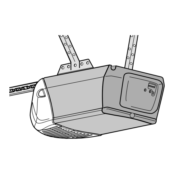
GARAGE DOOR OPENER
Models • 4500DIDM 1/2 HP
For Residential Use Only
Owner's Manual
Please read this manual and the enclosed safety materials carefully!
■
■
Fasten the manual near the garage door after installation.
The door WILL NOT CLOSE unless the Protector System
■
■
Periodic checks of the opener are required to ensure safe operation.
The model number label is located on the front panel of your opener.
■
®
®
• 4500DI-2DM 1/2 HP
®
is connected and properly aligned.
Advertisement
Table of Contents

Subscribe to Our Youtube Channel
Related Manuals for Doit 4500DIDM 1/2 HP


Summary of Contents for Doit 4500DIDM 1/2 HP
- Page 1 Made exclusively for Do It Best Corp. Fort Wayne, Indiana ® GARAGE DOOR OPENER Models • 4500DIDM 1/2 HP • 4500DI-2DM 1/2 HP For Residential Use Only Owner’s Manual Please read this manual and the enclosed safety materials carefully! ■...
-
Page 2: Table Of Contents
TABLE OF CONTENTS Introduction Adjustment 28-30 Safety symbol and signal word review ....2 Adjust the travel limits ......28 Preparing your garage door . -
Page 3: Preparing Your Garage Door
Preparing your garage door Before you begin: To prevent possible SERIOUS INJURY or DEATH: • Disable locks. • ALWAYS call a trained door systems technician if • Remove any ropes connected to garage door. garage door binds, sticks or is out of balance. An •... -
Page 4: Planning
Planning Identify the type and height of your garage door. Survey • Do you have an access door in addition to the garage your garage area to see if any of the conditions below door? If not, Model 7702CB Emergency Key Release is apply to your installation. -
Page 5: Planning
Planning (Continued) ONE-PIECE DOOR INSTALLATIONS Without a properly working safety reversal system, • Generally, a one-piece door does not require persons (particularly small children) could be reinforcement. If your door is lightweight, refer to the SERIOUSLY INJURED or KILLED by a closing garage information relating to sectional doors in Installation door. -
Page 6: Carton Inventory
Carton Inventory Your garage door opener is packaged in one carton which Hardware for assembly and installation is shown on the contains the motor unit and all parts illustrated below. next page. Save the carton and packing material until Accessories will depend on the model purchased. If installation and adjustment is complete. -
Page 7: Hardware Inventory
Hardware Inventory Separate all hardware and group as shown below for the assembly and installation procedures. ASSEMBLY HARDWARE Lock Washer 3/8" Lock Nut 1/4"-20 Nut 3/8" Bolt 1/4"-20x1-3/4" Master Idler Bolt Link (2) Trolley Threaded Shaft INSTALLATION HARDWARE Insulated Staples (Not shown) Carriage Bolt Wing Nut... -
Page 8: Assemble The Rail And Install The Trolley
ASSEMBLY STEP 1 Assemble the Rail & Install the Trolley To prevent INJURY from pinching, keep hands and fi ngers away from the joints while assembling the rail. To avoid installation diffi culties, do not run the garage door opener until instructed to do so. 3. -
Page 9: Fasten The Rail To The Motor Unit And Install The Idler Pulley
ASSEMBLY STEP 2 Fasten the Rail to the Motor Unit To avoid SERIOUS damage to garage door opener, 1. Insert a 1/4"-20x1-3/4" bolt into the cover protection use ONLY those bolts/fasteners mounted in the top of bolt hole on the back end of the rail as shown. Tighten the opener. -
Page 10: Install The Chain/Cable
ASSEMBLY STEP 4 Install the Chain/Cable To avoid possible SERIOUS INJURY to fi ngers from 1. Pull the cable around the idler pulley and toward the moving garage door opener: trolley. • ALWAYS keep hand clear of sprocket while 2. Connect the cable to the retaining slot on the trolley, as operating opener. -
Page 11: Tighten The Chain
ASSEMBLY STEP 3 Tighten the Chain Figure 1 1. Spin the inner nut and lock washer down the trolley Outer threaded shaft, away from the trolley. Trolley Lock Threaded Washer 2. To tighten the chain, turn outer nut in the direction To Tighten Outer Nut Shaft shown (Figure 1). -
Page 12: Determine The Header Bracket Location
INSTALLATION STEP 1 OPTIONAL Unfi nished CEILING Ceiling Determine the Header Bracket Location MOUNT HEADER Header Wall BRACKET Vertical Centerline To prevent possible SERIOUS INJURY or DEATH: of Garage Door • Header bracket MUST be RIGIDLY fastened to Structural structural support on header wall or ceiling, Supports otherwise garage door might NOT reverse when required. -
Page 13: Install The Header Bracket
INSTALLATION STEP 2 Wall Mount Install the Header Bracket You can attach the header bracket either to the wall above the garage door, or to the ceiling. Follow the instructions which will work best for your particular requirements. Do not install the header bracket over drywall. If installing into masonry, use concrete anchors (not provided). -
Page 14: Attach The Rail To The Header Bracket
INSTALLATION STEP 3 Attach the Rail to the Header Bracket 1. Position the opener on the garage fl oor below the header bracket. Use packing material as a protective base. NOTE: If the door spring is in the way you’ll need help. -
Page 15: Position The Opener
INSTALLATION STEP 4 Position the Opener To prevent damage to garage door, rest garage door Follow instructions which apply to your door type as opener rail on 2x4 placed on top section of door. illustrated. SECTIONAL DOOR OR ONE-PIECE DOOR WITH TRACK A 2x4 laid fl... -
Page 16: Hang The Opener
INSTALLATION STEP 5 Hang the Opener To avoid possible SERIOUS INJURY from a falling Three representative installations are shown. Yours may garage door opener, fasten it SECURELY to structural be different. Hanging brackets should be angled supports of the garage. Concrete anchors MUST be (Figure 1) to provide rigid support. -
Page 17: Install The Door Control
INSTALLATION STEP 6 Install the Door Control To prevent possible SERIOUS INJURY or DEATH from Locate the door control within sight of the door at a electrocution: minimum height of 5 feet (1.5 m) where small children • Be sure power is NOT connected BEFORE installing cannot reach, and away from all moving parts of the door door control. -
Page 18: Install The Light
INSTALLATION STEP 7 Install the Light To prevent possible OVERHEATING of the endpanel or 1. Press the release tabs on both sides of lens. Gently light socket: rotate lens back and downward until the lens hinge is • DO NOT use short neck or specialty light bulbs. in the fully open position. -
Page 19: Electrical Requirements
INSTALLATION STEP 9 Electrical Requirements To prevent possible SERIOUS INJURY or DEATH from electrocution or fi re: To avoid installation diffi culties, do not run the opener • Be sure power is NOT connected to the opener, and at this time. disconnect power to circuit BEFORE removing cover To reduce the risk of electric shock, your garage door to establish permanent wiring connection. -
Page 20: Install The Protector System
INSTALLATION STEP 10 Install The Protector System ® Be sure power is NOT connected to the garage door The safety reversing sensor must be connected and opener BEFORE installing the safety reversing sensor. aligned correctly before the garage door opener will To prevent SERIOUS INJURY or DEATH from a move in the down direction. - Page 21 INSTALLING THE BRACKETS Figure 1 DOOR TRACK MOUNT (RIGHT SIDE) Be sure power to the opener is disconnected. Install and align the brackets so the sensors will face each other across the garage door, with the beam no higher than Door Track 6"...
- Page 22 MOUNTING AND WIRING THE SAFETY Figure 5 REVERSING SENSORS Wing Nut Mounting: 1/4"-20 1. Slide a 1/4"-20x1/2" carriage bolt head into the slot on each sensor. Use wing nuts to fasten sensors to brackets, with lenses pointing toward each other across the door.
- Page 23 Connect to garage door opener: 1. Strip 7/16" (11 mm) of insulation from each set of wires. Separate white and white/black wires suffi ciently to connect to the opener quick-connect terminals. Twist like colored wires together. Insert wires into quick-connect holes: white to white and white/black to grey (Figure 10).
-
Page 24: Fasten The Door Bracket
INSTALLATION STEP 11 Fasten the Door Bracket Fiberglass, aluminum or lightweight steel garage doors WILL REQUIRE reinforcement BEFORE Follow instructions which apply to your door type as installation of door bracket. Contact your door illustrated below or on the following page. manufacturer for reinforcement kit. - Page 25 ONE-PIECE DOORS Please read and comply with the warnings and reinforcement instructions on the previous page. They apply to one-piece doors also. HARDWARE SHOWN ACTUAL SIZE • Center the door bracket on the top of the door, in line with the header bracket as shown. Mark either the left and right, or the top and bottom holes.
- Page 26 INSTALLATION STEP 12 Figure 1 Pulley Connect Door Arm to Trolley Follow instructions which apply to your door type as illustrated below and on the following page. SECTIONAL DOORS ONLY Outer Trolley Make sure garage door is fully closed. Pull the emergency Inner Clevis Pin Ring...
-
Page 27: Connect The Door Arm To The Trolley
ALL ONE-PIECE DOORS Figure 5 1. Assemble the door arm, Figure 5: CORRECT INCORRECT IMPORTANT: The groove on the straight door arm MUST face away from the curved door arm. Straight Straight Door Arm • Fasten the straight and curved door arm sections Door Arm together to the longest possible length (with a 2 or 3 Curved... -
Page 28: Adjustment
ADJUSTMENT STEP 1 Adjust the UP and DOWN Travel Limits Without a properly installed safety reversal system, Limit adjustment settings regulate the points at which the persons (particularly small children) could be door will stop when moving up or down. SERIOUSLY INJURED or KILLED by a closing garage door. -
Page 29: Adjust The Force
ADJUSTMENT STEP 2 Adjust the Force Without a properly installed safety reversal system, Force adjustment controls are located on the back panel persons (particularly small children) could be of the motor unit. Force adjustment settings regulate the SERIOUSLY INJURED or KILLED by a closing garage amount of power required to open and close the door. -
Page 30: Test The Safety Reversal System
ADJUSTMENT STEP 3 Test the Safety Reversal System Without a properly installed safety reversal system, persons (particularly small children) could be TEST SERIOUSLY INJURED or KILLED by a closing garage 1. With the door fully open, place a 1-1/2" (3.8 cm) board door. -
Page 31: Operation
OPERATION IMPORTANT SAFETY INSTRUCTIONS WARNING WARNING To reduce the risk of SEVERE INJURY or DEATH: 1. READ AND FOLLOW ALL WARNINGS AND 9. If one control (force or travel limits) is adjusted, the INSTRUCTIONS. other control may also need adjustment. 2. -
Page 32: Using The Wall-Mounted Door Control
Using the Wall-Mounted Door Control CARE OF YOUR OPENER Press the lighted push button to open or close LIMIT AND FORCE ADJUSTMENTS: the door. Press again to reverse the door FORCE CONTROLS Weather conditions may cause some during the closing cycle or to stop the door minor changes in door operation while it’s opening. -
Page 33: Having A Problem
HAVING A PROBLEM? 1. My door will not close and the light bulbs blink on Bell Wire my motor unit: The safety reversing sensor must be connected and aligned correctly before the garage door opener will move in the down direction. •... -
Page 34: Diagnostic Chart
Diagnostics Located on Motor Unit Bell Wire Installed Safety Reversing Sensor LED or Diagnostic Your garage door opener is programmed with self-diagnostic capabilities. The “Learn” button/diagnostic LED will fl ash Safety Reversing “Learn” Sensor Button a number of times then pause signifying it has found a potential issue. -
Page 35: Programming
PROGRAMMING NOTICE: If this Security ✚ ® garage door opener is operated with a non-rolling code transmitter, the technical measure in the receiver of the garage door opener, which provides security against code-theft devices, will be circumvented. The owner of the copyright in the garage door opener does not authorize the purchaser or supplier of the non-rolling code transmitter to circumvent that technical measure. -
Page 36: To Add, Reprogram Or Change A Keyless Entry Pin
To Add, Reprogram or Change a Keyless Entry PIN To change an existing, known PIN NOTE: Your new Keyless Entry must be programmed to operate your garage door opener. If the existing PIN is known, it may be changed by one person without using a ladder. -
Page 37: Repair Parts
REPAIR PARTS Rail Assembly Parts KEY PART DESCRIPTION 4A1008 Master link kit 41C5141-1 Complete trolley assembly 41A5665 Complete rail 144C56 Idler pulley 41A5807 Chain and cable 12D598-1 “U” bracket NOT SHOWN 183A163 Wear pads Installation Parts KEY PART NO. NO. DESCRIPTION 41A4166 Lighted door control button... -
Page 38: Motor Unit Assembly Parts
Motor Unit Assembly Parts (Down) LIMIT SWITCH ASSEMBLY Brown Contact Wire Grey Wire Drive Gear Center Limit (Up) Yellow Contact Contact Wire KEY PART KEY PART DESCRIPTION DESCRIPTION 41A5615 Chain Spreader 41A5525-14 Cover 41C4220A Gear and sprocket assembly. 41A2818 Limit switch drive & retainer Complete with: Spring 41D3452 Limit switch assembly... -
Page 39: Accessories
ACCESSORIES 953DID 3-Button SECURITY✚ ® Remote Control: 7702CB Outside Quick Release: Includes visor clip. Required for a garage with NO access door. 956D 3-Button Mini-Remote Control with 760DI Outdoor Key Switch: ® SECURITY✚ Operates the garage door With key ring and fastening strip. automatically from outside when remote control is not handy. -
Page 40: Repair Parts And Service
DO IT BEST CORP. SERVICE IS ON CALL OUR LARGE SERVICE ORGANIZATION SPANS AMERICA INSTALLATION AND SERVICE INFORMATION IS AS NEAR AS YOUR TELEPHONE SIMPLY DIAL OUR TOLL FREE NUMBER: 1-800-528-9131 Call our Toll Free Service number for a list of dealers in your area. HOW TO ORDER REPAIR PARTS Selling prices will be furnished on request or parts will be shipped at prevailing prices and you will be billed accordingly.
Need help?
Do you have a question about the 4500DIDM 1/2 HP and is the answer not in the manual?
Questions and answers