
Related Manuals for Samsung CE2618NR


Summary of Contents for Samsung CE2618NR
-
Page 1: Table Of Contents
MICROWAVE OVEN CE2618NR SERVICE Manual MICROWAVE OVEN CONTENTS 1. Precaution 2. Specifications 3. Operating Instructions 4. Disassembly and Reassembly 5. Alignment and Adjustments 6. Troubleshooting 7. Exploded Views and Parts List 8. Schematic Diagrams SRSC... -
Page 2: Exposure To Excessive Microwave Energy
PRECAUTIONS TO BE OBSERVED BEFORE AND DURING SERVICING TO AVOID POSSIBLE EXPOSURE TO EXCESSIVE MICROWAVE ENERGY (a) Do not operate or allow the oven to be (c) Before turning on microwave power operated with the door open. for any service test or inspection within (b) Make the following safety checks on the microwave generating all ovens to be serviced before activating... -
Page 3: Precaution
1. Precaution Follow these special safety precautions. Although the microwave oven is completely safe during ordinary use, repair work can be extremely hazardous due to possible exposure to microwave radiation, as well as potentially lethal high voltages and currents. 1-1 Safety precautions ( 11. - Page 4 1-2 Special Servicing Precautions (Continued) 17. When checking the continuity of the witches or transformer, always make sure that the power is OFF, and one of the lead wires is disconnected. 18. Components that are critical for safety are indicated in the circuit diagram by shading, or .
-
Page 5: Specifications
2. Specifications 2-1 Table of Specifications TIMER 60 MINUTES POWER SOURCE 230V 50Hz, AC POWER CONSUMPTION MICROWAVE : 1,200W GRILL : 1100W OUTPUT POWER FROM 100 TO 750W (IEC-705 TEST PROCEDURE) OPERATING FREQUENCY 2,450MHz MAGNETRON OM75P(31)ESS COOLING METHOD COOLING FAN MOTOR OUTSIDE DIMENSIONS 489(W) x 275(H) x 383(D) OVEN DIMENSIONS... -
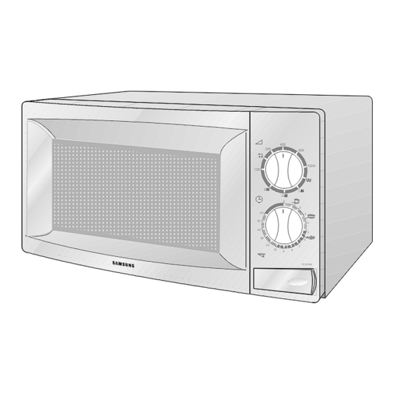
Page 6: Operating Instructions
3. Operating Instructions 3-1 Control Panel 3-2 Features & External Views VENTILATION HOLES LIGHT VARIABLE COOKING POWER CONTROL KNOB GRILL TIMER KNOB METAL RACK COUPLER TURNTABLE ROLLER RING OPEN DOOR PUSH BUTTON SAFETY DOOR LATCHES DOOR INTERLOCK HOLES 206mm 342mm 383mm 489mm - 4 -... -
Page 7: Disassembly And Reassembly
4. Disassembly and Reassembly 4-1 Replacement of Magnetron, Motor Assembly and Lamp Remove the magnetron including the shield case, permanent magnet, choke coils and capacitors (all of which are contained in one assembly). 1. Disconnect all lead wires from the magnetron and lamp. 2. -
Page 8: Replacement Of Door Assembly
4-3 Replacement of Door Assembly 4-3-1 Removal of Door Assembly Remove hex bolts securing the upper hinge and lower hinge. Then remove the door assembly. Upper Hinge SCREWS SCREW Lower Hinge 4-3-2 Removal of Door "C" Insert flat screwdriver into the gap between Door "A"... -
Page 9: Reassembly Test
4-3-5 Reassembly Test After replacement of the defective component parts of the door, reassemble it and follow the instructions below for proper installation and adjustment so as to prevent an excessive microwave leakage. 1. When mounting the door to the oven, be sure to adjust the door parallel to the bottom line of the oven face plate by moving the upper hinge and lower hinge in the direction necessary for proper alignment. -
Page 10: Replacement Of Control Circuit Board
4-6 Replacement of Control Circuit Board 4-6-1 Removal of Control Box Assembly 1. Disconnect the connectors from the control box assembly. 2. Remove screws securing the control box SCREWS assembly. 3. Remove the knobs of the control box Ass'y. 4. Remove the screw securing the timer. CONTROL BOX - 8 -... -
Page 11: Alignment And Adjustments
5. Alignment and Adjustments PRECAUTION 1. High voltage is present at the high voltage terminals during any cook cycle. 2. It is neither necessary nor advisable to attempt measurement of the high voltage. 3. Before touching any oven components or wiring, always unplug the oven from its power source and discharge the high voltage capacitor. -
Page 12: Troubleshooting
6. Troubleshooting WARNING FOR HIGH VOLTAGE 4000 VOLTS EXIST AT THE HIGH VOLTAGE AREA. DO NOT OPERATE THE OVEN WITH CABINET PARTS REMOVED. DO NOT REMOVE THE CABINET PARTS IF THE POWER SUPPLY CORD IS PLUGGED IN THE WALL OUTLET. UNPLUG THE POWER CORD BEFORE SERVICING. 6-1 Electrical Malfunction Parts Cause... - Page 13 6-1 Electrical Maltunction(continved) part Cause Diagnosis Remedy To increase the oven 1) Too small If a small amount of food is heated for a long time, water intowater into a load period of microwave may turn off during operation. the oven. Microwave turns off during 2)Defective...
-
Page 14: Unsatisfactory Cooking
6-2 Unsatisfactory Cooking Parts Cause Diagnosis Remedy 1) Open cathode of Check the terminals with a multimeter to see Replace magnetron. magnetron if the heater circuit is open. Check the H. V. Diode for continuity in the reverse and 2) Defective normal directions using megger. -
Page 15: High Voltage Capacitor
5-3 High Voltage Capacitor 1. Check continuity of the capacitor with the meter set at the highest resistance scale. 2. Once the capacitor is charged, a normal capacitor shows continuity for a short time, and then indicates 9M Ω . 3. -
Page 16: Output Power Of Magnetron
5-6 Output Power of Magnetron CAUTION MICROWAVE RADIATION PERSONNEL SHOULD NOT ALLOW EXPOSURE TO MICROWAVE RADIATION FROM MICROWAVE GENERATOR OR OTHER PARTS CONDUCTING MICROWAVE ENERGY. The output power of the magnetron can be measured by performing a water temperature rise test. Equipment needed : * Two 1-liter cylindrical borosilicate glass vessel (Outside diameter 190 mm) * One glass thermometer with mercury column... -
Page 17: Procedure For Measurement Of Microwave Energy Leakage
5-8 Procedure for Measurement of Microwave Energy Leakage 1) Pour 275±15cc of 20±5° C(68±9° F) water in a beaker which is graduated to 600cc, and place the beaker in the center of the oven. 2) Start to operate the oven and measure the leakage by using a microwave energy survey meter. -
Page 18: Exploded Views And Parts List
7. Exploded Views and Parts List 7-1 Exploded Views MC06 MD01 MM03 MD04 MC05 MM52 MM01 MD03 MM67 MM59 MD02 MM07 MM25 MM21 MM61 MM63 MC11 MM68 MM57 MM62 MD07 MM171 MD10 MM55 MM551 MM05 MM17 MM26 MM06 MC01 MM10 MM13 MM16 MC08... -
Page 19: Main Parts List
7-2 Main Parts List Code No. Description Specification Q'ty Remark MB01 DE96-00115C ASSY BODY LATCH CE2611N,NC2000(BUTTON) MB02 3405-000175 SWITCH-MICRO 250V,15A,200gf,SPST-NO MB03 3405-000178 SWITCH-MICRO 250V,15A,200gf,SPST-NO PRI, SEC MB04 DE66-00088A LEVER-SWITCH NC2000(0.6/0.8/1.2),PP,-,-,-,-,NTR,BUTTON-TYPE MB05 DE72-00138A BODY-LATCH PP,-,-,-,-,WHT,NC2000(0.6/0.8/1.2),BUTTON-TYPE MM01 DE70-00184A PANEL-OUTER SECC,T0.5,-,-,PCM,MW850WA(0.8CUFT),NC2000 MM03 DE39-00037B WIRE HARNESS-A CE2713N,-,-,-,-,-,-,-,-,-,230V50HZ,-,-,-,-,NC2000 MM05... - Page 20 7-3 Control & Door Parts List Code No. Description Specification Q'ty Remark MC01 ASSY CONTROL-BOX -,CE2618NR/BWT,PURE-WHT,- S.N.A MC03 DE72-00026U CONTROL-PANEL CE2618NR/BWT,-,-,-,-,W9501,- MC04 DE61-70076A SPRING-BUTTON HSWR,PI0.6,-,-,-,-,- MC05 DE66-20275A BUTTON-PUSH ABS(HR0370U),-,9G,P/WHT(W9501),-,-,- MC08 DE45-00003A TIMER TMFK60M1A1,-,-,-,-,-,-,310 GRILL MC09 DE64-00269A KNOB M1912,ABS,-,WHT,-,-,-,- MC12 3501-000309...
-
Page 21: Standard Parts List
7-4 Standard Parts List Code No. Description Specification Q'ty Remark DE60-10012A SCREW-TAP TITE TH,+,3,M4,L10,SWR10,ZPC2,TOOTH GRI-TCO DE60-10012A SCREW-TAP TITE TH,+,3,M4,L10,SWR10,ZPC2,TOOTH P-CORD DE60-10080B SCREW-WASHER PH,PI5,L10,SWRCH18A,ZP2,2S,-,- DE60-10080B SCREW-WASHER PH,PI5,L10,SWRCH18A,ZP2,2S,-,- DE60-10082H SCREW-A 2S-4X12,TOOTHED,-,-,-,-,-,-,-, B-LATCH DE60-10082H SCREW-A 2S-4X12,TOOTHED,-,-,-,-,-,-,-, B-PLATE DE60-10082H SCREW-A 2S-4X12,TOOTHED,-,-,-,-,-,-,-, B-UPPER DE60-10082H SCREW-A 2S-4X12,TOOTHED,-,-,-,-,-,-,-, C-BLOWER DE60-10082H... -
Page 22: Schematic Diagrams
8. Schematic Diagrams 8-1 Schematic Diagrams MAGNETRON HIGH VOLTAGE DIODE TO CHASSIS HIGH VOLTAGE CAPACITOR H.V.FUSE SYMBOL COLOR BROWN BLACK BLUE HIGH VOLTAGE TRANSFORMER - 20 -...
Need help?
Do you have a question about the CE2618NR and is the answer not in the manual?
Questions and answers