Table of Contents
Advertisement
Quick Links
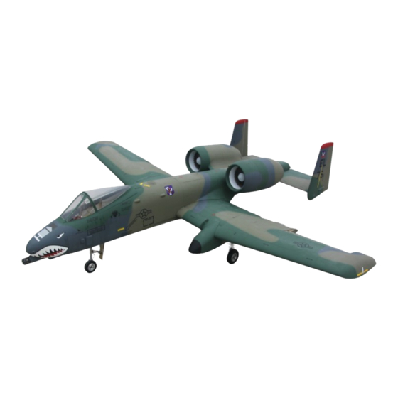
1/7.75 Scale Almost-Ready-To-Fly RC Jet
Assembly and operations manual
Spesifications
Type
: T.A.V.S ARF PRO
Scale : 1/7.75
Length : 80,3": (2040mm)
Span
: 87,8 ": (2230mm)
Weight : 27-29 Lbs ( 13-14 Kg)
Engine : 2 x 10-12Lbs (4 -6Kg) or EDF 120 – 130mm Fan, 160A Esc , 12-14 s Li-Po
Radio : 12 Channel 11-13 servo's
The A-10 Warthog by XtremeJets
Thank you very much for purchasing our Xtremejets ARF PRO A-10. Please note that the photos in this instruc-
tion manual show certain views from the prototypes. Some modifications and upgrades might have taken place by
the release of the model. We have tried to produce a very scale replica of this classic jet. Many scale options are
included with your model. This manual describes the assembling of " PRO" model. Landing gear and doors are
factory installed. Before you start building and setting-up your aircraft, please make sure you have read this in-
struction manual, and understood it. If you have any questions, please don't hesitate to contact us. Below are the
contact details:
Office Taiwan:
No.9.39 Lane,Yuag-Chang 2nd Street, Ren-Wu Hsiang, Kaohsiung Hsien, 814, Taiwan, R.O.C.
TEL: +886 9 3299 7923
FAX: + 886 7373 1215
http://www.skymasterjet.com
Sales : skymaste@seed.net.tw
Technical support : morne.m@pixie.co.za
SM © 2013
Advertisement
Table of Contents

Related Manuals for Sky Master A10 arf pro

Summary of Contents for Sky Master A10 arf pro
- Page 1 1/7.75 Scale Almost-Ready-To-Fly RC Jet Assembly and operations manual Spesifications Type : T.A.V.S ARF PRO Scale : 1/7.75 Length : 80,3”: (2040mm) Span : 87,8 ”: (2230mm) Weight : 27-29 Lbs ( 13-14 Kg) Engine : 2 x 10-12Lbs (4 -6Kg) or EDF 120 – 130mm Fan, 160A Esc , 12-14 s Li-Po Radio : 12 Channel 11-13 servo’s The A-10 Warthog by XtremeJets Thank you very much for purchasing our Xtremejets ARF PRO A-10.
-
Page 2: Table Of Contents
Assembly & Operation Manual Index: INTRODUCTION............................3 DISCLAIMER..............................3 WARNING…...............................3 ARF PAINT..............................4 FINISHING YOUR WHITE VIPER ARF......................4 HANDLING & TRANSPORTING .......................5 LIVE HINGE ……………………………..………..................5 TOOL LIST..............................6 HEALTH…..............................7 GENERAL ASSEMBLY TECHNIQUES....................…7 RADIO EQUIPMENT & ACCESSORIES…………….................8 KIT CONTENTS…….…………….......................9 OPTIONAL PARTS………………..………………..................10 CONTROL LINKAGES ..........................12 WINGS..............................12 STABILIZERS............................15 FIN &... -
Page 3: Introduction
Assembly & Operation Manual INTRODUCTION Thank you for purchasing Xtreme arf pro A10! We have put a lot of effort and time into this model. We at Skymaster strive to be a market leader in the ARF— jet market. We were the first company to produce ARF—jets in the world and we would like to continue being amongst the best. -
Page 4: Arf Paint
Assembly & Operation Manual ARF Paint The color finish on your A10 arf pro model was applied out of the mould. We have used only the highest standard automotive paints to finish your model. Should you damage the finish, Skymaster stock the color paint and hardener required for the repair. -
Page 5: Handling & Transporting
Assembly & Operation Manual HANDLING & TRANSPORTING Composite models are very light but strong. These characteristics do have a down side! It is brittle. Take care when handling your model. DO NOT ATTEMPT TO PICK UP AN FULLY FUELED MODEL BY THE LEADING EDGE! The leading edges will crack and delaminate. -
Page 6: Tool List
Assembly & Operation Manual Tools and Adhesives This is a fairly quick and easy plane to build, for a jet model, not requiring difficult tech- niques or special equipment, but even the building of XtremeJets aircraft requires some suitable tools! You will probably have all these tools in your workshop anyway, but if not, they are available in all good hobby shops, or hardware stores like "Home Depot"... -
Page 7: Health
Assembly & Operation Manual HEALTH Use a mask (available at auto paint stores) to protect from inhaling the glass or carbon fiber dust. Use this mask whenever you are sanding or cutting fiberglass or carbon fiber materials. Use a charcoal filter paint mask (available at auto paint supply stores) when spraying any primer or paint. -
Page 8: Radio Equipment & Accessories
Assembly & Operation Manual Radio equipment Failure to use the recommended servos, output arms, extensions, and hardware may result in a loss of control! Throughout this manual we make use of various types of servos and radio equipment! We have used JR equipment during the installation process. If you make use of an- other manufacturer, please use equipment with similar specifications! The A10 will require extension leads! Please use high quality extension leads. -
Page 9: Kit Contents
Assembly & Operation Manual Picture A Picture B Picture C A10 ARF PRO Contents: Picture A Fuselage incl nose gear + door installed + ventral fins + camera pod Fin & Rudder & Stabs & Elevators and main spar Wings incl L/G Incl Flap + Aileron + stall fairing + 2 x Engine POD... -
Page 10: Optional Parts
Assembly & Operation Manual OPTIONAL PARTS Landing Gear Set Photo 1 3 x Air Tanks 1 x Retract Valve 2 x Filler & 2 x Pressure Gauges 1 x brake valve 5 x Air Tubing, 10 x Quick Disconnect 8 x T-pieces, 2 x 4 way Photo 2 Fan (2) Pushrod Set... - Page 11 Assembly & Operation Manual Servo mounting hardware Photo 8 Photo 9 Powerbox Royal BVM UAT Photo 10 Photo 11 Fuel tanks Photo 12 Tygon Tubing Tank Hardware Photo 13 Photo 14 P-11...
-
Page 12: Control Linkages
Assembly & Operation Manual CONTROL LINKAGES Photo 15 WINGS NOTE: Make sure to have some sort of protective foam on the work bench. This will protect the paint surface from unwanted dents. Assemble both wings simultaneously. Mark √ each step. Check operation of Landing gear. - Page 13 Assembly & Operation Manual Locate all items needed to complete wings. Fit 2 L-shape servo brackets to 1 x JR DS3401 servos. Aileron servo must be mounted with horns facing up. The horn must be closest to control surface and furthest away for root. Secure servo horns and centre servo’s with TX.
- Page 14 Assembly & Operation Manual Photo 20 Photo 21 Make up flap pushrod. Make up 4. Fit pushrod to servo horn (long horns) and secure safety clip. Mark location on glass flap horn. Mill slots for 2 horns and glue horns with 30 minute epoxy. Slide pushrod through hole in trailing edge and fasten servo with 4 screws.
-
Page 15: Stabilizers
Assembly & Operation Manual STABILIZERS NOTE: Make sure to have some sort of protective foam on the work bench. This will protect the paint surface from unwanted dents. All linkages are inside. If u require the linkage to be outside, please modify by yourself. To remove stabilizers for repair to ele- vator servo will require removing tailpipe. -
Page 16: Fin & Rudder
Assembly & Operation Manual FIN & RUDDER NOTE: Make sure to have some sort of protective foam on the work bench. This will protect the paint surface from unwanted dents. Do 2 rudders. Note rudders are factory installed using piano wire hinge. Mark √ each step. Locate all parts needed for this section. -
Page 17: Fuselage
Assembly & Operation Manual FUSELAGE Make sure you have a good stand for fuselage. You will need to assemble the rest of the A10 on this stand. Photo 28 Photo 29 Route all servo wires, fuel pipes and air pipes along inner skin of rear fuselage. Glue ventral fins. -
Page 18: Tailpipe
Assembly & Operation Manual POD + TAIL PIPE (Note the angle of tail pipe) Photo 32 Photo 33 Fit the POD to fuselage and glue with 30 min epoxy. Open the hatch and fit the tailpipe. Use turbine to space the pipe. FUEL CELLS NOTE: Bad plumbing lead to flame outs. -
Page 19: Fuel Diagram
Assembly & Operation Manual FUEL CELL DIAGRAM (Make 2 sets of this) Photo 36 P-19... -
Page 20: Air System
Assembly & Operation Manual AIR SYSTEM Photo 37 Glue the air tanks with silicon. Large tank next to Nose gear and smaller tank rear of front fuselage. If fitting a opening canopy system I suggest using another air cyl- inder. Fit the 2 filler valves onto plywood plate. -
Page 21: Air Diagram
Assembly & Operation Manual For scale functions such as canopy you will require additional 2 way electronic valves. Photo 38 2 way AIR DIAGRAM Photo 39 Diagram for retracts P-21... -
Page 22: Turbine Installation
Assembly & Operation Manual TURBINE INSTALLATION Photo 40 Photo 41 Photo 42 Please follow the instructions supplied with your turbine. Secure turbine to turbine rail via hatch. Leave gap of 25mm between NGV and tailpipe. Repeat for other turbine. Make up extension leads for cables. Mark wires, fuel lines, gas lines and power cables for left or right turbine. -
Page 23: Cockpit & Canopy
Assembly & Operation Manual COCKPIT AND CANOPY (after painting) Photo 44 Photo 45 Photo 46 Photo 47 Remove canopy. Cut cockpit just before dashboard. Glue ply strip to fuselage at bottom of cockpit. This will support the cockpit from bottom. Slide the front section including dashboard into position. -
Page 24: Equipment Installation Into The F80 Arf
Assembly & Operation Manual EQUIPMENT INSTALLATION INTO A10 Equipment installation is a personal venture. There is one golden rule: Do it as neat and logical as possible! This will make fault finding and service of components eas- ier. The A10 basically consist of 6 circuits! 1. -
Page 25: Before You Fly
Assembly & Operation Manual BEFORE YOU FLY It is assumed that the builder of this kit has acquired the basic skills and knowledge necessary to make a safe and functional radio control installation into a model. Therefore, these notes are intended only to assist that experience. When inserting the main spar into wing, make sure it only enters the amount required. - Page 26 Assembly & Operation Manual Take-Off Do some taxi tests before your flight! Make sure you are familiar with all settings and make sure the model track straight on the ground without rudder input. Choose a fine day for the maiden flight. Do not force a maiden flight! Select take off flap or flight mode 1 and open throttle.
-
Page 27: Edf Installation
Assembly & Operation Manual EDF INSTALLATION P-27...
Need help?
Do you have a question about the A10 arf pro and is the answer not in the manual?
Questions and answers