Table of Contents
Advertisement
Advertisement
Table of Contents

Summary of Contents for Comsoft XPS
- Page 1 XPS/XPS-E User's Manual COMSOFT...
-
Page 2: Xps/Xps-E User's Manual
The information contained therein can be amended without prior notice and does not represent any obligation on the part of COMSOFT. We do not assume any kind of responsibility for possible inconsistencies and their consequences. This work including all its parts is copyrighted. -
Page 3: Table Of Contents
1 Introduction....................1 2 Setting into Operation ................... 2 2.1 Connection of the Gateway..............3 2.1.1 XPS Desk Model ................3 2.1.2 XPS-E Top Hat Rail Model.............. 4 2.1.3 Proceeding ..................5 2.2 Test of PROFIBUS Connection ............... 5 2.3 Parameterisation..................6 2.4 set_prm Parameterisation ................. - Page 4 Contents XPS/XPS-E User's Manual 5.2 Serial Interface ..................28 5.2.1 Connector Assignment RS232 (XPS and XPS-E)......28 5.2.2 Cabling RS232................29 5.2.2.1 Cabling without Hardware Handshake........29 5.2.2.2 Cabling with Hardware Handshake ........29 5.2.3 Connector Assignment RS422/485 (XPS-E only) ......30 5.2.4 Cabling RS422 without Hardware Handshake.......
-
Page 5: List Of Tables
XPS/XPS-E User's Manual Contents List of Tables Table 1: set_prm .....................7 Table 2: slave_diag ..................9 Table 3: Baud Rate of Serial Interface Octet 12 ..........10 Table 4: Character Transmission Modes Octet 13 .........10 Table 5: Handshake Modes Octet 14 .............11 Table 6: Data Transmission Modes Octet 16 ..........12... - Page 6 Contents XPS/XPS-E User's Manual List of Figures Figure 1: Typical Connection of an XPS/XPS-E Gateway ........1 Figure 2: Connectors and Interfaces of XPS ............3 Figure 3: Connectors and Interfaces of XPS-E...........4 Figure 4: Data Reception in Poll Mode ............16 Figure 5: Receive data in serial triggered mode (trigger character : 0x0A) ..18 Figure 6: Data Reception in Request Mode............20...
-
Page 7: Figure 1: Typical Connection Of An Xps/Xps-E Gateway
XPS/XPS-E User's Manual Contents 1 Introduction The intelligent PROFIBUS-DP gateways of COMSOFT's XPS series allow the coupling of any serial devices with RS232 or RS422/485 interface to PROFIBUS-DP according to the European Standard EN50170. The protocol conversions required for the coupling are executed either by means of a transparent universal driver or by loadable device-specific converters. -
Page 8: Setting Into Operation
XPS/XPS-E User's Manual 2 Setting into Operation When developing the XPS products, COMSOFT put great stress on an easy installation. Following this aim, no external devices, e.g. configuration tools on a PC are required to execute the configuration. All connections are realised by D-SUB connectors, power plug (EN 60320) or spring clip terminals which can all be accessed and loosened easily. -
Page 9: Figure 2: Connectors And Interfaces Of Xps
XPS/XPS-E User's Manual Contents 2.1 Connection of the Gateway 2.1.1 XPS Desk Model Front Side RS232- PROFIBUS-DP Status LED Interface Interface Address Terminator ON/OFF Switch Power Supply Rear Side Figure 2: Connectors and Interfaces of XPS COMSOFT... -
Page 10: Figure 3: Connectors And Interfaces Of Xps-E
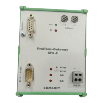
Contents XPS/XPS-E User's Manual 2.1.2 XPS-E Top Hat Rail Model PROFIBUS Address Switch Interface RUN-LED BUS-FAIL-LED MODE-LED TX-LED RX-LED Serial Interface Power Supply Connector Figure 3: Connectors and Interfaces of XPS-E COMSOFT... -
Page 11: Proceeding
XPS/XPS-E. 4. Plug in the power supply. In case of XPS this is done by means of a power plug (EN 60320) at the rear side of the device. The power supply of the XPS-E is connected by spring clips at the front side. -
Page 12: Parameterisation
2.4. 2. Check the parameterisation with slave_diag . 3. Then use the command chk_cfg to configure the XPS/XPS-E. Prior to that, the configuration can be read with the command get_cfg from XPS/XPS-E. If chk_cfg is executed directly after the initialisation, the maximum data_exchange telegram length is loaded from XPS/XPE-E. -
Page 13: Set_Prm Parameterisation
XPS/XPS-E User's Manual Contents 2.4 set_prm Parameterisation The Bytes 1-7 are PROFIBUS-DP standard parameters, Byte 8-23 are device- specific parameters ( usr_prm ). Octet Parameter Name Value Station_status 0x80* WD_fact_1 0x00 WD_fact_2 0x00 Min T Ident_Number [0] 0x95 Ident_Number [1]... -
Page 14: Gsd File
Contents XPS/XPS-E User's Manual 2.4.1 GSD File Next to standard parameters the parameters for the serial interface are included in the GSD file. They are listed under the User_Prm_Data . The values correspond to those described under chapter 2.3. A modification of these parameters can be made by any kind of ASCII editor. -
Page 15: Slave_Diag Device Diagnostics
XPS/XPS-E User's Manual Contents 2.4.2 Slave_diag Device Diagnostics Octet 1-7 are PROFIBUS-DP Standard, Octet 8-14 are the device-specific diagnostics parameters (external diagnostics). Octet Parameter Value Station_status_1 Bit7 Diag.Master_Lock Bit6 Diag.Prm_Fault Bit5 Diag.Invalid_Slave_Response Bit4 Diag.Not_Supported Bit3 Diag.Ext_Diag Bit2 Diag.Cfg_Fault Bit1 Diag.Station_Not_Ready Bit0 Diag.Station_Non_Existent... -
Page 16: Parameter Description
Contents XPS/XPS-E User's Manual 2.4.3 Parameter Description The parameters marked with (*) are the default values. These are used if inadmissible parameters are entered during parameterisation. 2.4.3.1 Baud Rate Baud Rate (bit/s) Value (dec) Value (hex) 0x01 0x03 0x06 1.200 0x0C 2.400... -
Page 17: Handshake Flow Control
XPS/XPS-E User's Manual Contents 2.4.3.3 Handshake Flow Control If data is exchanged via the serial interface, XPS/XPS-E supports the following modes for the handshake: • No Handshake • Hardware Handshake . The receive data flow can be controlled at the respective device by setting or re-setting the RTS-/CONTROL signal (CTS/INDICATION=0 ->... -
Page 18: Dp-Data Transmission Mode
Octet 17 BIT0: RS232<->RS422 – Serial interface physics With this parameter the interface physics can be set to RS232(0) or RS485(1). This parameter is only applicable for XPS-E. The desktop model (XPS) does only have an RS232 physics. BIT1: double Baudrate... -
Page 19: Trigger Character For Serial Triggert Mode
XPS/XPS-E User's Manual Contents 2.4.3.7 Trigger character for Serial triggert mode Here the trigger character for the serial triggerd mode is set. If the seriell receive data stream contains the same sign, all received data up to this character are sent to the DP-Master inclusive the trigger character. -
Page 20: Data Exchange
XPS/XPS-E User's Manual 3 Data Exchange Data exchange of XPS/XPS-E is exclusively realised by means of the PROFIBUS-DP service data_exchange . The data to be sent by the master correspond to the output data of data_exchange.req , the data received correspond to the input data of data_exchange.res . -
Page 21: Send Data
Contents 3.1 Send Data To send data via XPS/XPS-E onto a serial end device, the send flag of XPS/XPS-E must be reset (ref. 4.2 Communication Status, Bit 0 = 0), as otherwise the send data to XPS/XPS-E will be discarded. For a send job, the following data must be included into the telegram. -
Page 22: Figure 4: Data Reception In Poll Mode
XPS/XPS-E User's Manual 3.2.1 Poll Mode In this mode XPS/XPS-E returns with every data_exchange the data received up to the present time. Apart from the receive data and their lengths a receive data number is entered into the telegram. This confirmation number is automatically incremented if new receive data is available in the telegram. - Page 23 XPS/XPS-E enters the old confirmation number as no new data has been received at the serial interface. The receive data length is set to 0. XPS/XPS-E has again received new data. The confirmation number is incremented by one and the data returned correspondingly by the data_exchange.res telegram to the Master.
-
Page 24: Figure 5: Receive Data In Serial Triggered Mode (Trigger Character : 0X0A)
XPS/XPS-E User's Manual 3.2.2 Serial triggered Mode In serial triggered mode XPS/XPS-E waits for the termination of the receive data by the trigger character defined within the external user parameters of XPS/XPS-E (usually LF in ASCII-strings). The receive confirmation number is not increased as long as no trigger character is received. -
Page 25: Request Mode
3.2.3 Request Mode In the request mode the XPS/XPS-E only sends receive data if a modified receive-request number is contained in the request telegram. The data are not returned in the first response telegram but in the response telegram of the subsequent data_exchange service. -
Page 26: Figure 6: Data Reception In Request Mode
S 3 2 EN S = Status Figure 6: Data Reception in Request Mode The data_exchange.req telegram is sent to the XPS/XPS-E which already has received the first characters. It returns them, however, only in the subsequent response telegram data_exchange.res. - Page 27 The data that are returned are the data received at point in time No further reception command to XPS/XPS-E. XPS/XPS-E returns again the last sent data. XPS/XPS-E has already received new data. No further reception command to XPS/XPS-E. XPS/XPS-E returns again the last sent data.
-
Page 28: Figure 7: Combined Send- And Receive Request
(transmission command number, length of transmission data, data). Please note that the data are only accepted and transmitted by the XPS/XPS-E if the transmission command number in the data_exchange.req telegram to the XPS has changed. -
Page 29: Status And Error Messages
XPS/XPS-E User's Manual Contents 4 Status and Error Messages 4.1 External Device Diagnostics External device diagnostics can be realised by means of the service slave_diag Octet 8 of the response telegram contains the device status and is encoded as follows:... -
Page 30: Figure 9: Byte Definition Of Communication Status
RS_PORT_TX_DATA Data are being transmitted. not significant RS_PORT_PARITY_ERROR Parity error of receive data of serial interface. RS_PORT_RX_DATA_AVAIL XPS/XPS-E has data in receive buffer. XOFF_CTS_FLAG XOFF was received or CTS is inactive. OUTPUT_DATA_LEN_FAILURE user data length exceeds maximal data_exchange length minus 3... -
Page 31: Connector Assignment And Cabling
XPS/XPS-E User's Manual Contents 5 Connector Assignment and Cabling 5.1 PROFIBUS 5.1.1 Connector Assignment The PROFIBUS connection is executed according to EN50170 as 9-pin female D-SUB with the following assignment: Pin RS485 Signal Function Direction Ref. Shielding B/B´ RxD/TxD-P Data (+) -
Page 32: Figure 10: Assignment Of Profibus Terminator Type A
XPS/XPS-E User's Manual 5.1.2 PROFIBUS Terminating Resistor For correct operation of XPS/XPS-E both bus terminations of the line segment must be provided with a terminator. This terminator must match with the impedance level of the line. Typically, in case of new PROFIBUS installations, Type A will be used. -
Page 33: Figure 11: Connection Of A Profibus-Dp Slave Within A Segment
PROFIBUS installation please refer to the PROFIBUS Installation Guidelines of the PROFIBUS User Organisation (PNO, Order No.: 2.112). In case of XPS a bus termination is integrated and can be activated via the NOTE switch at the front side of the device. -
Page 34: Serial Interface
Contents XPS/XPS-E User's Manual 5.2 Serial Interface 5.2.1 Connector Assignment RS232 (XPS and XPS-E) The connection is realised via a 9-pin D-SUB plug. Signal CCITT Function Direction Data Carrier Detect Receive Data Transmit Data 108.2 Data Terminal Ready Ground Data Set Ready... -
Page 35: Figure 12: Rs232 Cabling Without Hardware Handshake
XPS/XPS-E User's Manual Contents 5.2.2 Cabling RS232 5.2.2.1 Cabling without Hardware Handshake XPS/XPS-E End Device Assignment Assignment 9pol 9pol 25pol Signal Signal Figure 12: RS232 Cabling without Hardware Handshake 5.2.2.2 Cabling with Hardware Handshake XPS/XPS-E End Device Assignment Assignment 9pol... -
Page 36: Connector Assignment Rs422/485 (Xps-E Only)
Contents XPS/XPS-E User's Manual 5.2.3 Connector Assignment RS422/485 (XPS-E only) The connection is realised via a 9-pin D-SUB plug. Signal Function Direction I(B) Indicate (-) R(A) Receive Data (+) T(A) Transmit Data (+) T(B) Transmit Data (-) Ground R(B) Receive data (-) -
Page 37: Figure 15: Rs422 Cabling With Hardware Handshake
XPS/XPS-E User's Manual Contents 5.2.5 Cabling RS422 with Hardware Handshake XPS/XPS-E End Device Assignment Assignment 9pol 15pol Signal Signal T(A) R(B) T(B) R(A) R(A) T(B) R(B) T(A) I(A) C(B) I(B) C(A) C(A) I(B) C(B) I(A) Figure 15: RS422 Cabling with Hardware Handshake... -
Page 38: Frequently Asked Questions: Faq
DP-Master Status message: Status 0xC3 (no acknowledge) Check the following points: • Does the station address of the XPS/XPS-E correspond to the setting of the PROFIBUS Master device? • Are the bus parameters set correctly? • Is the bus terminated correctly (switch position of the terminator integrated in XPS)? •... -
Page 39: Technical Data
XPS/XPS-E User's Manual Contents 7 Technical Data 7.1 XPS 7.1.1 PROFIBUS-DP Interface Transmission protocol: PROFIBUS-DP according to EN50170-3 Slave coupler Transmission rates: 9.6Kbit/s , 19.2Kbit/s, 93.75Kbit/s, 187.5Kbit/s, 500Kbit/s, 1.5Mbit/s, 3Mbit/s automatic adjustment Potential segregation: Opto-coupler interface and DC/DC transducer Isolation voltage U>500V... -
Page 40: Rs232 Interface
Contents XPS/XPS-E User's Manual 7.1.2 RS232 Interface Interface: RS232 interface with handshake signals (RTS, CTS) Transmission rates: 150bit/s, 300bit/s, 600bit/s, 1.200bit/s, 2.400bit/s, 4.800bit/s, 9.600bit/s, 19.200bit/s Character Transmission: 8N1, 7N2, 7E1, 7O1 Handshake: HW (RTS/CTS), SW(XON/XOFF), none XOFF Timeout: Adjustable to max. 25,5 seconds... -
Page 41: Technical Data
XPS/XPS-E User's Manual Contents 7.1.5 Technical Data Case: steel sheet, zinc-coated and lacquered Dimensions: 175mm x 145mm x 45mm (LxWxH) Weight: Power supply: 230VAC / 25mA -25 ° C .. +70 ° C Storage temperature: 0 ° C .. +55 ° C non-condensing... -
Page 42: Xps-E
Contents XPS/XPS-E User's Manual 7.2 XPS-E 7.2.1 PROFIBUS-DP Interface Transmission protocol: PROFIBUS-DP acc. to EN50170-3 Slave coupler Transmission rates: 9.6kbit/s, 19.2kbit/s, 93.75kbit/s, 187.5kbit/s, 500kbit/s, 1.5Mbit/s, 3Mbit/s, 6Mbit/s, 12Mbit/s automatic adjustment Potential segregation: Opto-coupler interface and DC/DC transducer Isolation voltage U>500V... -
Page 43: Serial Interface
XPS/XPS-E User's Manual Contents 7.2.2 Serial Interface Interface: RS232 interface with Handshake signals (RTS, CTS). RS422/485 interface with Handshake signals (CONTROL, INDICATION). Interface physics can be adjusted via PROFIBUS by means of User_Parameter. Transmission rates: 150bit/s, 300bit/s, 600bit/s, 1.200bit/s, 2.400bit/s, 4.800bit/s, 9.600bit/s, 19.200bit/s... -
Page 44: Technical Data
Contents XPS/XPS-E User's Manual 7.2.5 Technical Data Case: synthetic profile with aluminium front panel, lacquered Dimensions: 126mm x 90mm x 38mm (LxWxH) Weight: 190g Voltage range: 18 – 30VDC Power assumption: 100mA (24VDC) -25 ° C .. +70 ° C Storage temperature: 0 °... -
Page 45: Figure 16: Profibus-Dp Certificate No. Z00284
XPS/XPS-E User's Manual Contents 8 PROFIBUS-DP Certificate Figure 16: PROFIBUS-DP Certificate No. Z00284 COMSOFT... -
Page 46: Ce- Conformity Declaration
Contents XPS/XPS-E User's Manual 9 CE- Conformity Declaration We herewith declare that the PROFIBUS / RS232-RS422/485 Gateway XPS, XPS-E corresponds to the requirements stated in the EU standards 89/336/EWG and 92/31/EWG. The board corresponds to the following standards: EN 50082-2 and EN 55022...
Need help?
Do you have a question about the XPS and is the answer not in the manual?
Questions and answers