
Summary of Contents for ROYALL 8095
- Page 1 Installation INDOOR SOLID FUEL FURNACE Models: 8095, 8130, 8130HD www.royallfurnace.com 325 South Park Street, Reedsburg, WI 53959 Phone 608-768-8508...
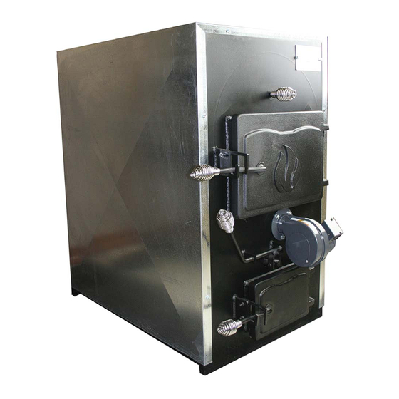
- Page 2 Thank you for purchasing a ROYALL Indoor Forced Air Solid Fuel Furnace. is a quality Indoor Solid Fuel Appliance designed to effectively heat structures. Please read and follow all safety instructions to ensure optimal performance and safety. The installation and operation of the is quite simple.
- Page 3 SERIAL NUMBER DEALER CITY STATE Reason for choosing Royall over other brands __Price __Features __Safety __Previously owned Royall __Recommended to you __Other PRODUCT REGISTRATION CARD Warranty is in effect from the date of purchase upon receipt of this card. NAME...
- Page 4 Place Stamp Here Brand Products 325 South Park Street Reedsburg, WI 53959 Place Stamp Here Brand Products 325 South Park Street Reedsburg, WI 53959...
-
Page 5: Table Of Contents
CONTENT GENERAL SAFETY..............................Pg SPECIFICATIONS..........................Pg PRODUCT DESCRIPTION........................Pg INSTALLATION INSTALLATION PLACEMENT......................Pg CLEARANCES............................Pg INSPECTING CONTENTS........................Pg FIREBRICK INSTALLATION......................... Pg INSTALLATION OF SHROUD......................Pg INSTALLATION WITH AN EXISTING FURNACE (SERIES)..............Pg FILTER BOX (OPTIONAL)........................Pg TYPICAL SYSTEM SCHEMATICS......................Pg 14-15 VENTING ASSEMBLY........................... -
Page 6: Safety
SAFETY ALL STATE or LOCAL CODES take precedence and MUST be observed. These models have been constructed along U L391-99 parameters. Many of the recommendations in this manual are also based on the National Fire Protection Association Code 211. NOTE: Before installing or starting operation, read and familiarize yourself with all instructions. -
Page 7: Specifications
SPECIFICATIONS INDOOR FORCED AIR FURNACE MODELS Features 8095 8130 8130HD Dimensions: W x L x H (Inches) 22x32x38 24x32x48 24x32x48 Estimated BTU Output 95,000 130,000 150,000 Weight (LBS) Fire Box Volume 5.6 cubic ft. 7.4 cubic ft. 7.4 cubic ft. -
Page 8: Installation Placement
PRODUCT DESCRIPTION (CONT.) The combustion process is driven by a draft blower mounted on the front of the appliance. When the room thermostat calls for heat, the draft blower starts adding combustion air to increase the fi re intensity. If the exiting air temperature exceeds 200°... - Page 9 INSTALLATION PLACEMENT (CONT.) Failure to keep furnace area clear and free of combustible materials, DANGER gasoline DANGER and other fl ammable liquids and vapors can result in severe personal injury, death or substantial property damage. SOLID FUEL APPLIANCES SHALL NOT BE INSTALLED IN A LOCATION WHERE GASOLINE OR OTHER FLAMMABLE VAPORS ARE LIKELY TO BE PRESENT.
-
Page 10: Clearances
CLEARANCES NON-COMBUSTIBLE: Surfaces must have these clearances: Front – 48” Back – underneath the chimney and Sides – 12”. COMBUSTIBLE: Surfaces must have these clearances: Front – 48” Back – 30” Sides – 18” smoke pipe -27” (Side) 18” (Back). The following clearances are recommended for maintenance: Back –30”... -
Page 11: Inspecting Contents
INSPECTING CONTENTS COMPONENTS SHIPPED LOOSE INSIDE: ROYALL INDOOR FURNACE Fire Brick Fan Limit Control Fan Center Control Draft Blower With Gasket 4 x 4 Electric Box BX Wire 72” of 14/2 BX Wire 60” of 14/3 BX Connector, 90 Elbow (1) -
Page 12: Firebrick Installation
FIREBRICK INSTALLATION The appliance comes with the fi rebrick boxpackaged inside appliance. MODEL 8095 8130 8130HD (16) Full Bricks & (2) Cut Bricks Install Bricks as follows: 1. Remove T-Bar from back of the fi re box. 2. Install (2) full bricks and (2) half bricks in the back of the fi re box. -
Page 13: Installation Of Shroud
INSTALLATION OF SHROUD SHROUD PREPARATION 1) For “Series” installation (see page 12): A) Cover the fi lter box opening on the rear of the appliance. Manufacture a cover from standard ducting material. B) Cut an opening in shroud side for cold air return duct. Opening should match duct dimensions out of the existing furnace to maintain system balance. -
Page 14: Installation With An Existing Furnace (Series)
INSTALLATION WITH AN EXISTING FURNACE (SERIES) Description of Operation 1) The circulation blower on the existing furnace draws air through the cold air return and the furnace. 2) The air passes into the bottom of the solid fuel furnace, which heats the air. 3) The heated air circulates through the heating ducts. -
Page 15: Filter Box (Optional)
FILTER BOX (0PTIONAL) If installing the ROYALL furnace in Parallel with the existing furnace (see page 14), construct and install the fi lter box as follows: 1) Mount the Crculation Blower on the rear of the appliance using 4-1/4” x 3/4” screws. -
Page 16: Typical System Schematics
5) If the existing furnace fi res, back draft damper (2) will automatically open and back draft damper (1) will automatically close. REQUIRED ADDITIONAL COMPONENTS 1) Filter box 2) Circulation blower 3) (2 ) Back draft dampers (not available from Royall) 4) Water Loop November 2013 Page... - Page 17 TYPICAL SYSTEM SCHEMATICS (CONT.) INSTALLATION 1) Install a new cold air return from existing ducts to the solid fuel furnace. 2) Install a back draft damper (air flow baffle) between the solid fuel furnace hot air outlet and the existing furnace hot air plenum. 3) Install a back draft damper (air fl ow baffl e) between the existing furnace and the existing hot air plenum.
-
Page 18: Venting Assembly
VENTING INSTALLALLATION All single wall chimneys must be at least 18” from any combustible surface. DANGER Fire can result, causing severe personal injury, death or substantial property damage. A major cause of chimney-related fi res is failure to maintain required clearances DANGER (air spaces) to combustible materials. - Page 19 VENTING INSTALLALLATION (CONT.) CHIMNEY HEIGHT To prevent downdrafts, chimney, or vent without a listed cap should extend at least 3 feet above the highest point where it passes through a roof and at least 2 feet higher than any portion of a building within a horizontal distance of 10 feet.
-
Page 20: Component Assembly Installation
COMPONENT ASSEMBLY INSTALLALLATION 1) FAN LIMIT CONTROL A) The fan limit control may be installed on either side. B) Drill a 3/4” diameter hole approximately 2-1/2” inches down centered on the desired side. C) Insert the sensor of the fan limit control and attach the control with the provided sheet metal screws. -
Page 21: Electrical Installation
ELECTRICAL INSTALLALLATION BASIC ELECTRICALS For your safety, turn off electrical power supply at service entrance panel before making any electrical connections to avoid possible electric shock hazard. Failure to do so can cause severe personal injury or death. Thermostat Power shut off while making connections. DANGER Failure to do so may result in severe personal injury or death. - Page 22 ELECTRICAL INSTALLALLATION (CONT.) 2) CONTROL CENTER JUNCTION BOX A) Install the “A” leg of the wring harness from the switch junction box. B) Install the “C” leg to the fan limit control. • “C” leg has (3) wires: Black, White and Red. C) Install the “D”...
- Page 23 ELECTRICAL INSTALLALLATION (CONT.) 4) Room Thermostat A) Close the control center junction box. B) Attach thermostat wire to the heating contacts on the thermostat R+W (refer to thermostat manufacturer’s instructions). THERMOSTAT C) Attach other end of thermostat wire to “R” and “G” contacts on the control center.
- Page 24 ELECTRICAL INSTALLALLATION (CONT.) Schematic Wiring Diagram Switch Junction Box MASTER GREEN THERMOSTAT To 115v To: Circulation GREEN Power Blower GREEN Low Voltage Thermostat Wire WHITE RODGERS HONEY WELL FAN LIMIT SWITCH FAN LIMIT SWITCH To: Switch Junction Box GREEN LOAD Limit To: Fan/Limit COIL...
-
Page 25: Operation
OPERATION FOLLOW ALL SAFETY PRECAUTIONS BEFORE STARTING A FIRE • Cycle the FAN switch to check for proper draft blower operation. • Inspect the loading door gasket before lighting the fi rst fi re and a few days after, looking for any indications of a poor seal. -
Page 26: Setting The Fan Limit Control
SETTING THE FAN LIMIT CONTROL 1) Set the lower arm (left tab) to 130. This sets the temperature below which the circulation blower turns “OFF”. 2) Set the middle arm (middle tab) to 170. This sets the temperature above which the circulation blower turns “ON”. -
Page 27: Burning
BURNING BURNING WOOD Burn only split cordwood that has been seasoned for 12-18 months. Burning unseasoned wood is waste- ful and ineffi cient using much of the combustion energy to boil off the excess moisture. Ideally the wood should be split to aid in seasoning and should be around 25% moisture content by weight. The following are general guidelines for wood selection: •... - Page 28 BURNING (CONT.) BURNING COAL (CONT.) REFUELING 1) Place FAN switch in OFF position. 2) Pull Smoke bypass damper rod out and wait one minute. 3) Open the fuel loading door slowly. 4) Pull the glowing coal to the front of the fi re box. Try not to disturb the fi re too much. 5) Add new coal to the back of the fi re box, being careful not to seal off the top.
- Page 29 BURNING (CONT.) CREOSOTE FORMATION All wood burning devices create some creosote. 1) When wood is burned slowly, it produces tar and other organic vapors, which combine with expelled moisture to form creosote. 2) Creosote vapors condense in the relatively cool chimney fl ue of a slow burning fi re. 3) As a result, creosote residue accumulates on the fl ue lining.
-
Page 30: Emergency Actions
EMERGENCY ACTIONS OVER HEATING 1) Manually turn off the draft fan at the fan switch (place switch in OFF position). 2) DO NOT TURN OFF THE MASTER SWITCH . The circulation blower must have power to remove heat from the appliance. 3) Turn the thermostats fully up in the structure being heated by furnace to remove heat from the appliance as fast as possible. -
Page 31: Maintenance
MAINTENANCE Keeping the solid fuel furnace in good repair will result in more effi cient operation and longer appliance life. You are responsible for safely maintaining the unit. Follow the Service and Maintenance procedures given throughout this manual and in component literature shipped with the appliance. Failure to perform the service and maintenance could result in damage to the boiler or system. - Page 32 MAINTENANCE (CONT.) BEGINNING OF SEASON • Chimney: Remove cap from chimney. Inspect chimney. Ensure chimney is not blocked (check for animal or bird nests). • Loading door : Oil door hinges and latch. Inspect gaskets. Verify that door seals tightly (apply thin coat of lipstick to loading fl ange, shut door, reopen and inspect marking on the gasket).
-
Page 33: Trouble Shooting
B) Verify that the fuel is properly seasoned (20-25% moisture content). C) Burning small pieces of extra dry wood can cause creosote. Try burning large pieces of wood for a few days. D) If problem persists call your installer or local ROYALL Representative. 3) PROBLEM: DRAFT BLOWER RUNS CONTINUOUSLY A) Set the thermostat at the lowest setting. - Page 34 TROUBLE SHOOTING (CONT.) D) A buildup of ashes in the ash trough can restrict the exhaust of combustion air. E) A buildup of ashes on top of the grates can restrict combustion air. F) Ensure that the chimney has adequate draft (.06” w.c. minimum). G) Ensure that no other appliances are connected to the chimney.
-
Page 35: Replacement Parts Listing
5 HOLE FOR 4 ROCKER GRATE ROCKER FLAT BAR 4 GRATES RF-ROCKERFLTBR5HL SYSTEM AND HARDWARE REAR GRATE CAS-REAR-FRM FRONT GRATE CAS-FRONT-FRM ROCKER GRATE CAS-ROCKER 2 SIZES LARGE & CAST BAFFLE CAS-BAFFLE (SMALL 8095 ONLY) SHAKER HANDLE RBSHAKERHANDLE November 2013 Page 33... - Page 36 3 / 1 6 x 2 1 / 2 C o t t e r P i n D a m p e r R o d S p r i n g H a n d l e Reference # Item Name Royall Part # Notes SPRING HANDLE HAR-HAN-SPRING DAMPER ROD...
- Page 37 1 / 4 - 2 0 x 1 1 / 4 H H C S 1 / 4 - 2 0 N U T A S H PA N G - L AT C H Reference # Item Name Royall Part # Notes 10” x 14” FUEL DOOR CAS-DOOR10x14 DRAFT BLOWER W/H GASKET BL60...
- Page 38 Parts listed on page 36 are not shown in Replacement Parts Listing Diagrams found on pages 33-35. Visit us on the web at Royallfurnace.com for all other part related questions. Reference # Item Name Royall Part # Notes 5/8 GASKET ROPE GAS-ROPE 5/8 FUEL DOOR &...
-
Page 39: Warranty
TAL, INDIRECT OR PUNITIVE DAMAGES FOR BREACH OF ANY EXPRESS WARRANTY. For prompt product warranty claims, notify the ROYALL dealer from whom the product was purchased. If this action does not result in warranty resolution, contact ROYALL at 325 South Park Street Reedsburg, WI 53959, with details in support of the warranty claim. - Page 40 800.944.2516 325 S. Park Street, Reedsburg, WI 53959 royallfurnace.com...
Need help?
Do you have a question about the 8095 and is the answer not in the manual?
Questions and answers