Kenwood TKR-850 Service Manual
Uhf fm repeater
Hide thumbs
Also See for TKR-850:
- Service manual (71 pages) ,
- Instruction manual (2 pages) ,
- Programming reference manual (83 pages)
Table of Contents
Advertisement
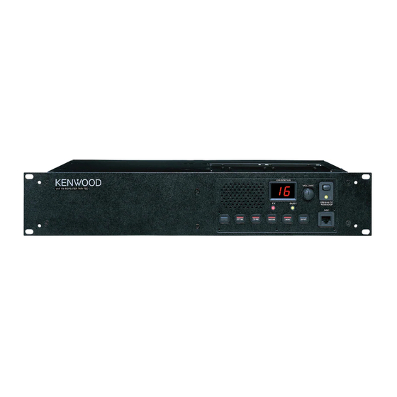
UHF FM REPEATER
TKR-850
SERVICE MANUAL
REVISED III
This service manual applies to products 60700001 or subsequent serial number.
In terms of the products with the serial numbers earlier than 60700001, refer to the TKR-850 service manual as per part number
B51-8557-20 and B51-8676-00.
UHF FM REPEATER TKR-850
Antenna cable (N)
(E30-3419-05)
D-sub cable assy
(E37-0904-05)
TEST/SPKR connector assy
(E37-0913-05)
GENERAL ................................................................. 2
SYSTEM SET-UP ..................................................... 2
OPERATING FEATURES ......................................... 3
REALIGNMENT ........................................................ 4
INSTALLATION ........................................................ 5
MODIFICATION ....................................................... 8
DISASSEMBLY FOR REPAIR ................................ 10
CIRCUIT DESCRIPTION ......................................... 11
SEMICONDUCTOR DATA ..................................... 18
COMPONENTS DESCRIPTION ............................. 20
PARTS LIST ............................................................ 22
EXPLODED VIEW .................................................. 34
PACKING ................................................................ 36
ADJUSTMENT ....................................................... 37
Front panel
(A62-0934-03)
Fuse (Blade, 15A/32V)
Key top
(F05-1537-05) x 2
(K29-5460-02)
Antenna cable (BNC)
(E30-3418-05)
DC cord (Ext DC in)
(E30-3414-05)
DC backup terminal
(E70-0402-05)
CONTENTS
© 2004-10 PRINTED IN JAPAN
B51-8557-30 ( N ) 1219
Knob (Volume)
(K29-5389-03)
Modular jack
(E08-0877-05)
TERMINAL FUNCTION ......................................... 46
INTERCONNECTION DIAGRAM ........................... 50
FINAL UNIT (X45-374X-XX) ............................. 52
DISPLAY UNIT (X54-3330-21) .......................... 56
TX-RX UNIT (X57-696X-XX) (A/2) ................... 60
TX-RX UNIT (X57-696X-XX) (B/2) ................... 64
RX VCO UNIT (X58-480X-XX) .......................... 68
TX VCO UNIT (X58-481X-XX) .......................... 69
SCHEMATIC DIAGRAM ........................................ 70
BLOCK DIAGRAM .................................................. 83
KES-5 (EXTERNAL SPEAKER) .............................. 86
SPECIFICATIONS................................................... 87
Knob (DC source)
(K29-9106-04)
Advertisement
Table of Contents

Related Manuals for Kenwood TKR-850


Summary of Contents for Kenwood TKR-850
-
Page 1: Table Of Contents
B51-8557-30 ( N ) 1219 This service manual applies to products 60700001 or subsequent serial number. In terms of the products with the serial numbers earlier than 60700001, refer to the TKR-850 service manual as per part number B51-8557-20 and B51-8676-00. -
Page 2: General
TKR-850 GENERAL / SYSTEM SET-UP INTRODUCTION PERSONAL SAFETY SCOPE OF THIS MANUAL The following precautions are recommended for personal safety : This manual is intended for use by experienced techni- • DO NOT transmit until all RF connectors are secure and cians familiar with similar types of commercial grade commu- any open connectors are properly terminated. -
Page 3: Operating Features
TKR-850 OPERATING FEATURES • “E2” is displayed when the channel data is not written. 1. Two 7-segment LED displays • Channel display (1~16) : While operating normally in user mode. • “E3” is displayed when PLL is unlocked. Receiver PLL unlocked = BUSY LED blinks. -
Page 4: Realignment
User mode Use this mode for normal operation. The data can be input to or read from TKR-850 and edited on the screen. The programmed or edited data can be PC mode Use this mode to make various settings by printed out. -
Page 5: Installation
3. Set the firmware to be updated by file name item. (Rear Connectors) 4. Turn the TKR-850 power on with the [PF1] key held down. This unit has two external power supply connectors : Main Hold the key down for one second until the 7-segment DC and Backup. - Page 6 CN606 (15-pin) on the rear of the radio is 4W/4Ω. Use external speaker KES-4 or KES-5. 3-1. Connection for the KES-4 or KES-5 With the TKR-850 CN605 ■ When taking the AF output from the TEST/ SPKR connector (15-pin) on the rear of the radio The following tools are required for changing the connec- tor.
- Page 7 TKR-850 INSTALLATION Note : 4. Accessory Cabinet Relationship between TEST/SPKR connector (15-pin) con- You can install optional accessories, such as a DC power nection and speaker output. supply or duplexers in the accessory cabinet. When pins 9 and 12 are shorted : Built-in internal speaker is used.
-
Page 8: Modification
TKR-850 INSTALLATION / MODIFICATION 5. Key Cover 7. Installing Name Plates To avoid accidentally pressing the keys, you can install the Punch out the name plate card. Then insert the plates key cover. onto the reltative function keys. You can reconfigure the name plates at any time. - Page 9 3. Single Antenna If the external DC power supply is connected to the Main The TKR-850 can be used as a base station by sharing an DC connector and a backup battery (12V rechargeable type) is external antenna connector for both transmitting and receiv- connected to the Backup connector at the same time, the ing data.
-
Page 10: Disassembly For Repair
TKR-850 MODIFICATION / DISASSEMBLY FOR REPAIR 3-2. Connection DISASSEMBLY FOR REPAIR 1. Solder the prepared coaxial cable to the final unit. 2. Connect the pin connector of the coaxial cable to CN18 of 1. How to Remove the Panel Assy (ABS) the TX-RX unit. -
Page 11: Circuit Description
2-1. Front-end Circuit 1. Outline The front-end circuit consists of BPF L2, RF amplifier Q1, The TKR-850 is a UHF/FM repeater designed to operate in and BPF L4/L5. The helical BPF covers frequency ranges 440 the frequency range of 400 to 512MHz. - Page 12 TKR-850 CIRCUIT DESCRIPTION 2-3. IF Amplifier 3. Transmitter Circuit The first IF signal is amplified by Q2 and Q3, and then en- The transmitter circuit consists of the following circuits : 3- ters IC9 (FM system IC). The signal is heterodyned again 1 microphone circuit, 3-2 modulation level adjustment circuit, with a second local oscillator signal (44.395MHz) with in IC9...
- Page 13 TKR-850 CIRCUIT DESCRIPTION 3-3. Driver and Final Power Amplifier Circuit The transmit signal is generated by the TX VCO (A2), am- plified by Q11, and sent to final unit (X45-374). This amplified signal is amplified by Q1, Q2, Q3 and Q4, and is passed to the FINAL stage.
- Page 14 TKR-850 CIRCUIT DESCRIPTION 4-2. Transmitter PLL 4. PLL Frequency Synthesizer The transmitter PLL circuit is located in VCO unit A2 (X58- The PLL frequency synthesizer circuit consists of the fol- 481) on TX-RX unit (X57-696 A/2), and consists of VCXO X3, lowing circuits : 4-1 receiver PLL circuit, 4-2 transmitter PLL VCO’s (Q350 : K,K2,E, Q351 : K3), a single-chip PLL IC IC300,...
- Page 15 TKR-850 CIRCUIT DESCRIPTION 5-5. Display Circuit 5. Control Circuit The display circuit (X54-333) contains two 7-segment The control circuit mainly located in the control section of LEDs D506, D507 (orange), D503 (red : transmission), two- TX-RX unit (X57-696 B/2) consists of the following : 5-1 CPU,...
- Page 16 TKR-850 CIRCUIT DESCRIPTION 5-6. DSP 5-7. Base-Band Circuit The DSP circuit filters transmit/receive audio signal and The base-band circuit switches between the modulation encode/decodes signaling (QT, DQT). This circuit consists of signal to the transmitter circuit, and remote audio and adjusts IC618, IC612, IC613, IC614, IC603, IC606, IC608, IC610, their levels.
- Page 17 TKR-850 CIRCUIT DESCRIPTION 5-10. 5-tone* Decode IC604 checks the square wave frequency for the pres- The 300 to 3000Hz frequency characteristics of the signal that enters the comparator are made flat by the circuit, and ence of the required tone, and if the tone matches, IC604 the band is made into that band required to detect 5-tone performs the subsequent required processing.
-
Page 18: Semiconductor Data
TKR-850 SEMICONDUCTOR DATA Main CPU : 30622M4A-487GP (TX-RX unit IC604) ■ Pin Function Pin No. Name Function Pin No. Name Function Aux I/O No.5 (Acc D-sub 25 pin) – Not used Aux I/O No.4 (Acc D-sub 25 pin) HOLD –... - Page 19 TKR-850 SEMICONDUCTOR DATA DSP : 320VC5402PGE (TX-RX unit IC618) ■ Pin Function Pin No. Name Function Pin No. Name Function NC1,NC2 – Not used (No connection) BDR0 Serial data receive input – HCNTL1 HPI control 1 DVDD – VDD for I/O pins (+3.3V) BDR1 –...
-
Page 20: Components Description
TKR-850 SEMICONDUCTOR DATA / COMPONENTS DESCRIPTION Final Unit (X45-374X-XX) Pin No. Name Function Ref. No. Part name Description EMU1/OFF Emulator 1 (to JTAG connector) Thermostat Test data output (to JTAG connector) Voltage regulator Test data input (to JTAG connector) DC amplifier... -
Page 21: Components Description
TKR-850 COMPONENTS DESCRIPTION Ref. No. Part name Description Ref. No. Part name Description D/A converter Q603 Transistor Inverter Shift register Q604 DC switch FM IF system Q605 Transistor Inverter IC10,11 Voltage regulator Q606 Transistor AF mute switch IC600 EEPROM Q607~609... -
Page 22: Parts List
Les articles non mentionnes dans le Parts No. ne sont pas fournis. Y : AAFES (Europe) X : Australia M : Other Areas Teile ohne Parts No. werden nicht geliefert. TKR-850 (Y54-319X-XX) FINAL UNIT (X45-374X-XX) Desti- Desti- Ref. No. Address Parts No. - Page 23 TKR-850 PARTS LIST FINAL UNIT (X45-374X-XX) Desti- Desti- Ref. No. Address Parts No. Description Ref. No. Address Parts No. Description parts nation parts nation CK73FB1H471K CHIP C 470PF C93-0555-05 CHIP C 5.0PF CC73FCH1H100D CHIP C 10PF C93-0556-05 CHIP C 6.0PF...
- Page 24 TKR-850 PARTS LIST FINAL UNIT (X45-374X-XX) DISPLAY UNIT (X54-3330-21) Desti- Desti- Ref. No. Address Parts No. Description Ref. No. Address Parts No. Description parts nation parts nation L40-8265-92 SMALL FIXED INDUCTOR (8.2NH) RK73GB1J471J CHIP R 1/16W L41-6865-20 SMALL FIXED INDUCTOR...
- Page 25 TKR-850 PARTS LIST DISPLAY UNIT (X54-3330-21) TX-RX UNIT (X57-696X-XX) Desti- Desti- Ref. No. Address Parts No. Description Ref. No. Address Parts No. Description parts nation parts nation ✽ C526 CK73FB1E334K CHIP C 0.33UF TX-RX UNIT (X57-696X-XX) 0-11 : K 0-12 : K2 0-13 : K3 2-70 : E...
- Page 26 TKR-850 PARTS LIST TX-RX UNIT (X57-696X-XX) Desti- Desti- Ref. No. Address Parts No. Description Ref. No. Address Parts No. Description parts nation parts nation C92-0628-05 CHIP-TAN 10UF 10WV C178 C92-0606-05 CHIP-TAN 4.7UF 10WV CK73GB1H102K CHIP C 1000PF C179 CK73GB1H103K CHIP C 0.010UF...
- Page 27 TKR-850 PARTS LIST TX-RX UNIT (X57-696X-XX) Desti- Desti- Ref. No. Address Parts No. Description Ref. No. Address Parts No. Description parts nation parts nation C705 CK73GB1E103K CHIP C 0.010UF C792-794 CK73GB1H102K CHIP C 1000PF C706 C92-0628-05 CHIP-TAN 10UF 10WV C795...
- Page 28 TKR-850 PARTS LIST TX-RX UNIT (X57-696X-XX) Desti- Desti- Ref. No. Address Parts No. Description Ref. No. Address Parts No. Description parts nation parts nation ✽ L79-1853-05 HELICAL BLOCK RK73GB1J122J CHIP R 1.2K 1/16W L40-1575-34 SMALL FIXED INDUCTOR (15NH) K2,K3 RK73GB1J102J CHIP R 1.0K...
- Page 29 TKR-850 PARTS LIST TX-RX UNIT (X57-696X-XX) Desti- Desti- Ref. No. Address Parts No. Description Ref. No. Address Parts No. Description parts nation parts nation RK73GB1J182J CHIP R 1.8K 1/16W R606 RK73GB1J473J CHIP R 1/16W RK73GB1J101J CHIP R 1/16W R607-613 R92-1252-05...
- Page 30 TKR-850 PARTS LIST TX-RX UNIT (X57-696X-XX) Desti- Desti- Ref. No. Address Parts No. Description Ref. No. Address Parts No. Description parts nation parts nation R710 RK73GB1J473J CHIP R 1/16W R794 RK73GB1J473J CHIP R 1/16W R712 RK73GB1J473J CHIP R 1/16W R795...
- Page 31 TKR-850 PARTS LIST TX-RX UNIT (X57-696X-XX) RX VCO UNIT (X58-480X-XX) Desti- Desti- Ref. No. Address Parts No. Description Ref. No. Address Parts No. Description parts nation parts nation TK14489V BI-POLAR IC Q611 DTC114EUA DIGITAL TRANSISTOR IC10 TA7808F ANALOGUE IC Q612...
- Page 32 TKR-850 PARTS LIST RX VCO UNIT (X58-480X-XX) TX VCO UNIT (X58-481X-XX) Desti- Desti- Ref. No. Address Parts No. Description Ref. No. Address Parts No. Description parts nation parts nation C379 CC73GCH1H040C CHIP C 4.0PF Q300,301 2SC4116(GR) TRANSISTOR C383 CK73GB1H471K CHIP C...
- Page 33 TKR-850 PARTS LIST TX VCO UNIT (X58-481X-XX) Desti- Desti- Ref. No. Address Parts No. Description Ref. No. Address Parts No. Description parts nation parts nation C379 CC73GCH1H040C CHIP C 4.0PF R368 RK73GB1J330J CHIP R 1/16W C380 CC73GCH1H0R5B CHIP C 0.5PF...
-
Page 34: Exploded View
TKR-850 EXPLODED VIEW : N09-2292-05 M2.6 x 6 : N30-2606-46 M4 x 6 : N30-4006-46 D M4 x 14 : N30-4014-46 M4 x 20 BLK : N30-4020-45 M3 x 6 (F) : N32-3006-46 G M4 x 8 (F) BLK : N32-4008-45... - Page 35 TKR-850 EXPLODED VIEW Kx14 35x2 A/2) Final (B/2) 47x2 Parts with the exploded numbers larger than 700 are not supplied.
-
Page 36: Packing
TKR-850 PACKING 52 Protection bag (H25-0029-04) 48 Cushion (G13-1801-04) 59 Foot (J02-0475-05) x 2 49 Cushion (G13-1802-04) 60 Foot (J02-0492-04) x 2 53 Protetion bag (H25-0747-04) 62 Grommet (J59-0302-05) x 2 61 Mounting hardware (J21-8402-04) C Pan head machine screw (N30-4006-46) x 2... -
Page 37: Adjustment
To connect the TX-RX unit A/2 (CN14) to the TX-RX unit B/ MIC (WHT) 2 (CN602) while in servicing, you can use the 36-pin flat MICG (SHIELD) AF VTVM cable, E37-0979-05, which is available from the KENWOOD (BLU) parts center. PTT SW (BLK) - Page 38 TKR-850 ADJUSTMENT Test Channel (Default) Test Signaling Decode tone Encode tone None None 450.10 450.00 480.10 480.00 400.10 400.00 440.10 440.00 None 100Hz square wave 465.10 465.00 496.10 496.00 415.10 415.00 455.10 455.00 QT 67.0Hz QT 67.0Hz 479.90 480.00 511.90 512.00...
- Page 39 (KPG-91D) for details. frequency of the channel to be used by the TKR-850. 3. Check whether the frequency rewritten under the “Test mode” of the FPU (KPG-91D) is correct, then select the...
- Page 40 TKR-850 ADJUSTMENT Measurement Adjustment Item Condition Specifications/Remarks Test- Unit Terminal Unit Parts Method equipment ± 0.1V 4. RX PLL lock 1) RX VCO A high TX-RX RX-CV RX VCO TC350 1.50V voltage CH : 11 K (A/2) (A3) CH : 10 K2,K3,E...
- Page 41 TKR-850 ADJUSTMENT Measurement Adjustment Item Condition Specifications/Remarks Test- Unit Terminal Unit Parts Method equipment 14. MCF 1) Connect the TG to CN2, then Tracking Rear RX ANT TX-RX L14 Adjust it to look like (Wide) connect CN4 to the spectrum generator (A/2) the wave Fig.
- Page 42 TKR-850 ADJUSTMENT Measurement Adjustment Item Condition Specifications/Remarks Test- Unit Terminal Unit Parts Method equipment ± 5mV 18. RD outut 1) Connect SSG to RX ANT. Rear RX ANT PC adj. level CH : 2 (Wide) 80mV (Wide) SSG output : –53dBm/501µV...
- Page 43 TKR-850 ADJUSTMENT Measurement Adjustment Item Condition Specifications/Remarks Test- Unit Terminal Unit Parts Method equipment ± 0.05kHz 23. DQT 1) CH : 2 MOD ANA Rear TX ANT PC adj. deviation Deviation meter filter 0.75kHz (Wide) HPF : OFF Deviation LPF : 3kHz...
- Page 44 TKR-850 ADJUSTMENT Measurement Adjustment Item Condition Specifications/Remarks Test- Unit Terminal Unit Parts Method equipment ± 0.1kHz 28. DTMF 1) CH : 2 MOD ANA Rear TX ANT PC adj. deviation Deviation meter filter 3.0kHz (Wide) HPF : OFF Deviation LPF : 15kHz...
- Page 45 TKR-850 ADJUSTMENT Measurement Adjustment Item Condition Specifications/Remarks Test- Unit Terminal Unit Parts Method equipment 34. Power 1) CH : 2 (High power) Power meter Rear TX ANT PC adj. down detect About 16W (High) (Factory-default) (Low) 2) CH : 2 (Low power) PC adj.
-
Page 46: Terminal Function
TKR-850 TERMINAL FUNCTION Final Unit (X45-374X-XX) Connector Terminal Terminal I/O Terminal function Name Connector Terminal Terminal I/O Terminal function Name STB1 Strobe data for shift register TX driver input signal (Coaxial) Clock data input Serial data input O High temperature detector signal... - Page 47 TKR-850 TERMINAL FUNCTION Connector Terminal Terminal I/O Terminal function Connector Terminal Terminal I/O Terminal function Name Name Enable input for RX PLL – No Connection Enable input for TX PLL display O Serial data output O Lock detector for RX PLL...
- Page 48 TKR-850 TERMINAL FUNCTION Connector Terminal Terminal I/O Terminal function Connector Terminal Terminal I/O Terminal function Name Name O Latch data output for DA converter I/O Programable I/O 1 RF power down signal input – Control line ground O Strobe output for shift register –...
- Page 49 TKR-850 TERMINAL FUNCTION Connector Terminal Terminal I/O Terminal function Connector Terminal Terminal I/O Terminal function Name Name 8V input through the ripple filter Speaker mute signal input “L”: Mute on RX PLL lock voltage No connection 9V input through the ripple filter...
-
Page 50: Interconnection Diagram
TKR-850 INTERCONNECTION DIAGRAM CN605 INT SP TX-RX UNIT B/2 TX-RX UN X57-696*-** X57-696 CN602 DISPLAY UNIT A/2 X54-333*-** 1.8C 1.8V AVR 8V A 3.3D 3.3V AVR 5V AVR 8CT(8C) 8V A CN600 5V AVR 5V AVR 5V AVR 3.3V AVR 3.3A... - Page 51 TKR-850 INTERCONNECTION DIAGRAM CN18 RX ANT TX-RX UNIT A/2 X57-696*-** MAIN DC CN15 MAIN DC – BACKUP BATTERY BACKUP – 8V AVR 5V AVR FINAL UNIT B/2 CN16 X45-374*-** 8V AVR 5V AVR FINAL UNIT A/2 X45-374*-** 9V AVR CN19...
- Page 52 CN605 CN18 RX ANT INT SP TX-RX UNIT B/2 TX-RX UNIT A/2 X57-696*-** X57-696*-** MAIN DC CN15 MAIN DC – CN602 DISPLAY UNIT A/2 BACKUP BATTERY BACKUP – X54-333*-** 1.8C 1.8V AVR 8V AVR 3.3D 3.3V AVR 5V AVR FINAL UNIT B/2 CN16 X45-374*-** 8CT(8C)
-
Page 53: Pc Board
TKR-850 PC BOARD FINAL UNIT (X45-374X-XX) 0-10 : K,E 0-11 : K2 0-12 : K3 Component side view (J72-0911-19) CN8 GND CN6 MAIN DC (BLACK) (RED) CN7 BACKUP (ORANGE) Back up battery Main DC CHARGE C173 C169 C120 FAB 1... - Page 54 TKR-850 PC BOARD FINAL UNIT (X45-374X-XX) 0-10 : K,E 0-11 : K2 0-12 : K3 Component side view (J72-0911-19) J72-0911-19 (A/2) C118 C165 C178 C120 C166 CN53 ANT SW Component side Layer 1 Layer 2 Layer 3 Layer 4 Foil side...
-
Page 55: Pc Board Final Unit (X45-374X-Xx)
TKR-850 TKR-850 PC BOARD PC BOARD FINAL UNIT (X45-374X-XX) 0-10 : K,E 0-11 : K2 0-12 : K3 FINAL UNIT (X45-374X-XX) 0-10 : K,E 0-11 : K2 0-12 : K3 Component side view (J72-0911-19) Component side view (J72-0911-19) J72-0911-19 (A/2) - Page 56 TKR-850 PC BOARD FINAL UNIT (X45-374X-XX) 0-10 : K,E 0-11 : K2 0-12 : K3 Foil side view (J72-0911-19) J72-0911-19 (A/2) C179 C109 C108 C157 Ref. No. Address Ref. No. Address...
- Page 57 TKR-850 PC BOARD FINAL UNIT (X45-374X-XX) 0-10 : K,E 0-11 : K2 0-12 : K3 Foil side view (J72-0911-19) C115 C114 C168 Back up battery Main DC C170 C105 C174 C109 C108 C101 C171 C103 C102 J72-0911-19 (B/2) Component side...
- Page 58 TKR-850 TKR-850 PC BOARD PC BOARD FINAL UNIT (X45-374X-XX) 0-10 : K,E 0-11 : K2 0-12 : K3 FINAL UNIT (X45-374X-XX) 0-10 : K,E 0-11 : K2 0-12 : K3 Foil side view (J72-0911-19) Foil side view (J72-0911-19) J72-0911-19 (A/2)
-
Page 59: Display Unit (X54-3330-21)
TKR-850 PC BOARD DISPLAY UNIT (X54-3330-21) Component side view (J72-0756-12) VR601 J601 IC504 D503 J72-0756-12 B/2 S501 S503 S504 S502 Q512... - Page 60 TKR-850 PC BOARD DISPLAY UNIT (X54-3330-21) Component side view (J72-0756-12) J72-0756-12 A/2 S507 POWER D505 D507 D506 MAIN BACK- IC504 IC505 D504 BUSY Component side S505 S506 Layer 1 Layer 2 Foil side Q514 Ref. No. Address IC504 IC505 Q512...
- Page 61 TKR-850 TKR-850 PC BOARD PC BOARD DISPLAY UNIT (X54-3330-21) Component side view (J72-0756-12) DISPLAY UNIT (X54-3330-21) Component side view (J72-0756-12) J72-0756-12 A/2 VR601 S507 POWER D505 D507 D506 MAIN BACK- J601 IC504 IC505 D503 D504 BUSY J72-0756-12 B/2 Component side...
- Page 62 TKR-850 PC BOARD DISPLAY UNIT (X54-3330-21) Foil side view (J72-0756-12) J72-0756-12 A/2 CP504 CP502 CP503 CP501 BACKUP MAIN DC R543 R606 R517 Q525 Q507 Q504 Q509 R538 BUSY R518 Q503 D508 D509 C516 C517 R525 C526 Component side C518 D502...
- Page 63 TKR-850 PC BOARD DISPLAY UNIT (X54-3330-21) Foil side view (J72-0756-12) CN601 C606 C603 C602 D602 D601 R601 J72-0756-12 B/2 CN502 C513 R522 C508 R511 R512 R529 R513 Q513 R533 IC501...
- Page 64 TKR-850 TKR-850 PC BOARD PC BOARD DISPLAY UNIT (X54-3330-21) Foil side view (J72-0756-12) DISPLAY UNIT (X54-3330-21) Foil side view (J72-0756-12) J72-0756-12 A/2 CN601 C606 C603 C602 CP504 CP502 D602 D601 CP503 CP501 BACKUP MAIN DC R601 R543 R606 R517 Q525...
-
Page 65: Tx-Rx Unit (X57-696X-Xx) (A/2)
TKR-850 PC BOARD TX-RX UNIT (X57-696X-XX) (A/2) 0-11 : K 0-12 : K2 0-13 : K3 2-70 : E Component side view (J72-0924-19 A/2) CN18 CN15 NARROW WIDE R181 CN14 Ref. No. Address Ref. No. Address Ref. No. Address IC10... - Page 66 TKR-850 PC BOARD TX-RX UNIT (X57-696X-XX) (A/2) 0-11 : K 0-12 : K2 0-13 : K3 2-70 : E Component side view (J72-0924-19 A/2) CN16 CN19 GND2 GND1 TP102 TX CV A2 : TX VCO (X58-481) C137 C139 GND2 GND1...
- Page 67 TKR-850 TKR-850 PC BOARD PC BOARD TX-RX UNIT (X57-696X-XX) (A/2) 0-11 : K 0-12 : K2 0-13 : K3 2-70 : E TX-RX UNIT (X57-696X-XX) (A/2) 0-11 : K 0-12 : K2 0-13 : K3 2-70 : E Component side view (J72-0924-19 A/2)
- Page 68 TKR-850 PC BOARD TX-RX UNIT (X57-696X-XX) (A/2) 0-11 : K 0-12 : K2 0-13 : K3 2-70 : E Foil side view (J72-0924-19 A/2) R136 R135 R168 GND2 R179 R106 C127 R148 R145 C129 R121 C211 C167 C123 or R173...
- Page 69 TKR-850 PC BOARD TX-RX UNIT (X57-696X-XX) (A/2) 0-11 : K 0-12 : K2 0-13 : K3 2-70 : E Foil side view (J72-0924-19 A/2) R171 C199 C198 C65 + R160 C197 R150 C163 C155 C154 + C218 R176 C72 +...
- Page 70 TKR-850 TKR-850 PC BOARD PC BOARD TX-RX UNIT (X57-696X-XX) (A/2) 0-11 : K 0-12 : K2 0-13 : K3 2-70 : E TX-RX UNIT (X57-696X-XX) (A/2) 0-11 : K 0-12 : K2 0-13 : K3 2-70 : E Foil side view (J72-0924-19 A/2)
- Page 71 TKR-850 PC BOARD TX-RX UNIT (X57-696X-XX) (B/2) 0-11 : K 0-12 : K2 0-13 : K3 2-70 : E Component side view (J72-0924-19 B/2) CN600 C806 L606 IC627 5-TONE C826 3.3D D600 C785 L601 R836 L604 Q612 C613 R603 IC601...
-
Page 72: Tx-Rx Unit (X57-696X-Xx) (B/2)
TKR-850 PC BOARD TX-RX UNIT (X57-696X-XX) (B/2) 0-11 : K 0-12 : K2 0-13 : K3 2-70 : E Component side view (J72-0924-19 B/2) C800 CN610 R781 CN609 C817 C789 IC629 CP600 L607 IC630 C801 CP601 C795 C798 C814 R654... - Page 73 TKR-850 TKR-850 PC BOARD PC BOARD TX-RX UNIT (X57-696X-XX) (B/2) 0-11 : K 0-12 : K2 0-13 : K3 2-70 : E TX-RX UNIT (X57-696X-XX) (B/2) 0-11 : K 0-12 : K2 0-13 : K3 2-70 : E Component side view (J72-0924-19 B/2)
- Page 74 TKR-850 PC BOARD TX-RX UNIT (X57-696X-XX) (B/2) 0-11 : K 0-12 : K2 0-13 : K3 2-70 : E Foil side view (J72-0924-19 B/2) C784 CN602 C787 R754 Q606 R762 C783 D627 Q611 Q609 C791 R811 R767 C815 R802 R745...
- Page 75 TKR-850 PC BOARD TX-RX UNIT (X57-696X-XX) (B/2) 0-11 : K 0-12 : K2 0-13 : K3 2-70 : E Foil side view (J72-0924-19 B/2) Q601 Q602 IC632 R832 C836 IC631 R831 R828 R818 C838 C837 R819 R826 C842 C833 R616...
- Page 76 TKR-850 TKR-850 PC BOARD PC BOARD TX-RX UNIT (X57-696X-XX) (B/2) 0-11 : K 0-12 : K2 0-13 : K3 2-70 : E TX-RX UNIT (X57-696X-XX) (B/2) 0-11 : K 0-12 : K2 0-13 : K3 2-70 : E Foil side view (J72-0924-19 B/2)
-
Page 77: Rx Vco Unit (X58-480X-Xx)
TKR-850 PC BOARD RX VCO UNIT (X58-480X-XX) 0-10 : K,E 0-11 : K2 0-12 : K3 (J72-0751-02) Component side view Foil side view J72-0751-02 A/2 J72-0751-02 A/2 C379 R368 C377 L362 R360 R366 R361 R363 C378 R356 R357 Q353 R367... -
Page 78: Tx Vco Unit (X58-481X-Xx)
TKR-850 PC BOARD TX VCO UNIT (X58-481X-XX) 0-10 : K,E 0-11 : K2 0-12 : K3 (J72-0752-12) Component side view Foil side view J72-0752-12 A/2 J72-0752-12 A/2 C379 R368 C377 L362 R366 C378 R376 R367 L360 L361 C374 R359 R358... -
Page 79: Schematic Diagram
TKR-850 SCHEMATIC DIAGRAM FINAL UNIT (X45-3740-XX) (A/2) T:7.57V T:7.61V T:7.91V R:0V R:0V R:0V 2SC3356(R24) 6.8n 470p 470p 2SC5110(O) 2SK2596 T:0.70V T:0.69V R:0V R:0V Q1-3 RF AMP 2SC4116(Y) DC SWITCH SURGE VOLTAGE PROTECTOR THERMOSTAT REGULATOR T:13.03V R:13.54V NJM78L05UA MAX6502UKP035 HYST 150k... - Page 80 TKR-850 SCHEMATIC DIAGRAM FINAL UNIT (X45-3740-XX) (A/2) DRIVE FINAL AMP C160 PD55008S RD60HUF1-01 TX ANT D4,5 RF DETECTOR RF SWITCH T:4.26V R:0V MA4PH633 DC AMP VOLTAGE C120 REFERENCE TA75W01FU 470p 0.022u IN2+ IN2- IN1+ 470k OUT-B IN1- D55,56 RF SWITCH...
- Page 81 FINAL UNIT (X45-3740-XX) (A/2) T:7.57V T:7.61V T:7.91V R:0V R:0V R:0V DRIVE FINAL AMP C160 PD55008S RD60HUF1-01 2SC3356(R24) TX ANT 6.8n 470p 470p 2SC5110(O) 2SK2596 T:0.70V T:0.69V R:0V R:0V D4,5 RF DETECTOR Q1-3 RF SWITCH RF AMP T:4.26V R:0V MA4PH633 DC AMP VOLTAGE C120 TA75W01FU...
- Page 82 TKR-850 SCHEMATIC DIAGRAM Note : The components marked with a dot ( • ) are parts of layer 1. DISPLAY UNIT (X54-3330-21) (A/2) D506 CP501 LA-501DD 470*4 S506 7SEGMENT S501 S502 S503 S504 S505 C519 0.01u SHIFT REGISTER Q517 UPA672T...
- Page 83 TKR-850 SCHEMATIC DIAGRAM DISPLAY UNIT (X54-3330-21) (A/2) D507 CP503 CP504 CP502 LA-501DD 470*4 470*4 470*4 7SEGMENT DC SW C520 0.01u SHIFT Q518 Q521 REGISTER UPA672T UPA672T DC SW DC SW Q’S DC SW Q519 UPA672T DATA DC SW VOLTAGE REGULATOR...
- Page 84 DISPLAY UNIT (X54-3330-21) (A/2) D506 D507 CP501 CP502 CP503 CP504 LA-501DD LA-501DD 470*4 470*4 470*4 470*4 S506 7SEGMENT 7SEGMENT S501 S502 S503 S504 S505 DC SW C519 0.01u C520 0.01u SHIFT SHIFT Q518 Q521 REGISTER REGISTER UPA672T UPA672T Q517 DC SW DC SW UPA672T DC SW...
- Page 85 TKR-850 SCHEMATIC DIAGRAM TX-RX UNIT (X57-696X-XX) (A/2) A2 SUB UNIT (TX VCO/PLL) (X58-4810-XX) D350 FREQUENCY D354 CONTROL MODULATION L352 R351 TX-CV (TP102) U-TXVCO (Used for K,E,K2) CN351 BUFFER C368 Q355 2SC4226(R24) C379 -6.0dBm L353 D352 Q350 R353 C356 L356 C374...
- Page 86 TKR-850 SCHEMATIC DIAGRAM TX-RX UNIT (X57-696X-XX) (A/2) A3 SUB UNIT (RX VCO/PLL) (X58-4800-XX) R368 L352 CN351 R351 BUFFER R354 Q355 V-RXVCOL 2SC4226(R24) C379 -3.0dBm C374 R359 C368 RX-CV (TP101) 0.5p FREQUENCY VCO OSC CONTROL Q350 DC SW L353 D352 C356...
- Page 87 TKR-850 SCHEMATIC DIAGRAM TX-RX UNIT (X57-696X-XX) (A/2) R144 4.7k TX SW C164 470p 1.26V R135 B:1.56V T:8.05V T:2.02V DC SW DC SW 2SB1132(Q,R) E:0.79V R:0V 2SB1386(R) DAN235K R:0V 7.84V C:6.25V C101 R106 T:0V R:2.02V R129 R130 R168 RF AMP DC SW...
- Page 88 TKR-850 SCHEMATIC DIAGRAM TX-RX UNIT (X57-696X-XX) (A/2) E04-0154-05 +3.0dBm CN19 FINAL UNIT (X45-3740-XX) (A/2)-CN1 SHIFT CONVERTER REGISTER M62354GP BU4094BCF CN15 E40-5703-05 FINAL UNIT STRB (X45-3740-XX) (A/2)-CN5 DATA CN16 E40-5632-05 FINAL UNIT (X45-3740-XX) (A/2)-CN3 Q’S CN14 E40-6009-05 S76-0401-05 28.5mV DC SW...
- Page 89 TX-RX UNIT (X57-696X-XX) (A/2) A2 SUB UNIT (TX VCO/PLL) (X58-4810-XX) R144 4.7k +3.0dBm E04-0154-05 CN19 C164 470p FINAL UNIT A3 SUB UNIT (RX VCO/PLL) (X58-4800-XX) TX SW (X45-3740-XX) 1.26V R135 (A/2)-CN1 B:1.56V T:8.05V E:0.79V T:2.02V DC SW 2SB1132(Q,R) DC SW SHIFT D350 DAN235K...
- Page 90 TKR-850 SCHEMATIC DIAGRAM Note : The components marked with • a dot ( ) are parts of layer 1. TX-RX UNIT (X57-696X-XX) (B/2) SURGE PROTECTOR D600 DA204U CN600 E40-6102-05 R605 BATT C600 100k 0.1u STB1 STB1 PTT/TXD1 TXD1 VOLTAGE DETECTOR...
- Page 91 TKR-850 SCHEMATIC DIAGRAM TX-RX UNIT (X57-696X-XX) (B/2) 5.03V R814 R659 R660 R661 CP613 1k*2 KEY4 KEY4 R817 3.24V KEY5 KEY5 5TONE CP620 CP614 1k*2 100*2 EMON EMON R662 R618 BYTE CNVSS CNVss CP603 100*2 CP615 10*4 RESET RESET XOUT R629...
- Page 92 TKR-850 SCHEMATIC DIAGRAM TX-RX UNIT (X57-696X-XX) (B/2) L606 L607 10u10 C754 470p C749 NC18 C750 0.01u NC17 CVDD7 R691 HCNTL0 HCNTL0 VSS6 BCLK BCLKR0 BCLKR1 BFSR0 LRCK BFSR1 BDR0 SDT0 R692 HCNTL1 HCNTL1 R813 BDR1 BCLKX0 BCLK C759 470p MCLK...
- Page 93 TKR-850 SCHEMATIC DIAGRAM TX-RX UNIT (X57-696X-XX) (B/2) AMPSW AMPSW 5V AVR IC624 IC627 XC62FP1802P TA78L05F 1.81V 5.03V 8.03V 1.8V AVR 1.8C VOUT OUTX INVERTER IC625 IC628 IC621 3.3V AVR XC62FP3302P TA78L05F 3.30V 5.02V TC7S00FU 5V AVR NAND GATE 3.3D VOUT...
- Page 94 TKR-850 SCHEMATIC DIAGRAM TX-RX UNIT (X57-696X-XX) (B/2) 13.07V C783 470p 13.07V AMPSW IC629 Q610 AUDIO AMP LA4422 2SJ506(S) DC SW 1.21V DC SW Q611 DTC114EUA Q609 DTC114EUA CURRENT DC SW PROTECTOR D627,628 REVERSE CURRENT C814 PROTECTOR 1000u25 C787 C811 R758...
- Page 95 TX-RX UNIT (X57-696X-XX) (B/2) 5.03V C783 470p 13.07V 13.07V SURGE AMPSW AMPSW AMPSW IC629 PROTECTOR Q610 AUDIO AMP 2SJ506(S) LA4422 D600 IC624 IC627 5V AVR DC SW 1.21V DA204U DC SW 1.81V XC62FP1802P 1.8V AVR 5.03V TA78L05F 8.03V Q611 CN600 E40-6102-05 L606 1.8C...
-
Page 96: Block Diagram
TKR-850 BLOCK DIAGRAM TX-RX unit (CONTROL) X57 CN605 INT SP CN604 DAT,CLK,SOE RSSI Display unit Shift Reg. X54-333 (B/2) MIC JACK TEST/SPKR IC623 VR601 A01~5 BU4094BCF AF VOL D626 PTT/TXD CN603 MINISMDE190 D603 HK/RXD CN601 Display unit CN501 X54-333 (A/2) - Page 97 TKR-850 BLOCK DIAGRAM -RX unit (CONTROL) X57-696 (B/2) IC624 XC62FP1802P 1.8V 1.8C IC625 IC628 XC62FP3302P TA78L05F 3.3V IC622 Q606 3.3D TC7S66FU DTC363EK AF AMP IC626 IC630 IC629 MUTE DAT,CLK,SOE,STB2 TA78L05F XC62FP3302P RSSI LA4422 RSSI 3.3V 3.3A Q605 Q610 DTC114EUA Shift Reg.5...
- Page 98 TKR-850 BLOCK DIAGRAM TX-RX unit X57-696 (A/2) 44.850MHz RF AMP MCF(W) DAN235K DAN235K L4,5 2SC357 RX ANT IF AMP IF AMP CN18 CN14 2SC3357 2SC3356 RX VCO 2SC3356(R24) 2SC3357 MCF(N) VCOA FM IC 9CLR IC9 : TK14489V VCOB RSSI 2SC3356...
-
Page 99: External Speaker)
TKR-850 KES-5 (EXTERNAL SPEAKER) When Using an External Speaker 1. Make sure the unit’s power is tuned off. 2. When using the external speaker, remove the jumper lead from the connector, and attach the speaker cable. 3. When not using the external speaker, replace the jumper lead and insert the connector into the speaker jack (pin9 and 12). - Page 100 TKR-850 SPECIFICATIONS (K,K2,K3 TYPE) GENERAL Frequency Range ........ K : 450 to 480MHz K2 : 480 to 512MHz K3 : 400 to 430MHz Number of Channels ......16 channel Channel Spacing ......... Wide : 25kHz Narrow : 12.5kHz (PLL channel stepping 5kHz/6.25kHz) Operating Voltage .......
- Page 101 Unit 3712-3724, Level 37, Tower one Metroplaza, 223 Hing Fong Road, KENWOOD ELECTRONICS U.K. LIMITED Kwai Fong, N.T., Hong Kong KENWOOD House, Dwight Road, Watford, Herts., KENWOOD ELECTRONICS SINGAPORE PTE LTD. WD18 9EB United Kingdom 1 Ang Mo Kio Street 63, Singapore 569110...
Need help?
Do you have a question about the TKR-850 and is the answer not in the manual?
Questions and answers