Table of Contents
Advertisement
Quick Links
Advertisement
Table of Contents

Related Manuals for Baxi Fires Division Memphis 5

Summary of Contents for Baxi Fires Division Memphis 5
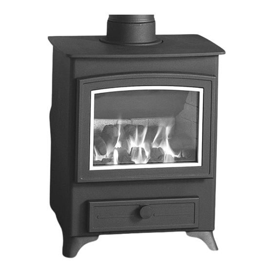
- Page 1 Operating & Installation Manual Memphis 5 & 7 Gas Stoves (Memphis 7 Gas Stove) Memphis 5 G.C No. 0504401 Memphis 7 G.C No. 0504411 PLEASE RETAIN THESE INSTRUCTIONS FOR FUTURE REFERENCE Baxi Fires Division, Wood Lane, Erdington Birmingham B24 9QP FOR USE IN COUNTRIES GB &...
- Page 2 Your Post Code b.) Type of Fire c.) Model/Name d.) Serial Number e.) The Fault, Problem or Request www.baxifires.co.uk Baxi Fires Division Wood Lane, Erdington, Birmingham B24 9QP Memphis 5 & 7 Gas stoves...
-
Page 3: Table Of Contents
Spare Parts 23-26 Fitting The Feet SERVICE RECORD Flue System 11-13 Service Record Fire Location Final Factory Checklist Combustible Shelf Clearances Hearth Requirements Connecting The Gas Supply Pressure Test Sequence Fire Testing Installation Check List Memphis 5 & 7 Gas stoves... -
Page 4: Introduction
Protective clothing is not • Use gloves to provide additional grip. required when handling these items but it is recommended that gloves are worn and Memphis 5 & 7 Gas stoves... -
Page 5: Statutory Requirements
Warning: If it is known or suspected that an operational or ignition fault exists on the appliance, it must not be used until it has been investigated and corrected by a qualified gas engineer. Memphis 5 & 7 Gas stoves... -
Page 6: Operating Instructions
Gas Rate 0.391m /hour 0.529m /hour Cold Setting 1.5mb 3.5mb Pressure Min. Heat Setting Heat Input 2.4 kW 3.3 kW (net) Gas Rate 0.254 m hour 0.349 m /hour CLASS 4 NOx CLASS CLASS 4 Memphis 5 & 7 Gas stoves... -
Page 7: Fitting The Lining Panels
Fig.3b below) Fig. 3e) Fig. 3e Liner panels assembled in the fire. Fig. 3b Fitting the R/H side lining Once the lining panels are fitted, arrange the coals. See “Arranging the coals” on page 8. Memphis 5 & 7 Gas stoves... -
Page 8: Arranging The Coals
Step 2 Place the rear matrix cut out section over the base matrix and centralise the assembly between the end tabs of the location bar. Ensure the rear matrix is pushed back against the location bar. (Fig 4b) Fig 4b Memphis 5 & 7 Gas stoves... -
Page 9: Lighting & Controlling The Fire
For minimum heat output, rotate the control knob Step 1b. Keep the control knob pressed in and turn clockwise to the LOW position. (Fig 5d) anti-clockwise to the pilot position. (Fig 5b) Fig 5b Memphis 5 & 7 Gas stoves... - Page 10 Fig 5e Step 3. To turn the main burner off while keeping the pilot alight, rotate the operating knob back to the PILOT position. (Fig 5e) Fig 5f Memphis 5 & 7 Gas stoves...
-
Page 11: Installation
The termination of the outlet at the top of the flue NACS (National Association of Chimney also needs to comply with the Building Sweeps): telephone 01785 811732 Regulations. The minimum effective height of the Memphis 5 & 7 Gas stoves... - Page 12 Fig 6c REAR FLUE Fig 7a Open Hearth Fit and seal a ‘T’ section (with soot box) directly into the flue spigot. The maximum horizontal section allowed is 150mm. Memphis 5 & 7 Gas stoves...
-
Page 13: Fire Location
100 mm is recommended. Fig 7c. Reference non-combustible side walls a minimum of 100mm is recommended. Do not place any furniture or furnishings (including curtains) within 1 metre of the fire. Memphis 5 & 7 Gas stoves... -
Page 14: Combustible Shelf Clearances
1. Graph 1.Combustible Shelf Clearances The recommended minimum height from the extreme top surface of the fire to the underside of a non combustible shelf is 100mm. Memphis 5 & 7 Gas stoves... -
Page 15: Hearth Requirements
After fitting the supply, operate the gas cock (supplied) and check all joints up to the termination of the supply pipe for gas tightness using a soap/water solution and the pressure drop method. Memphis 5 & 7 Gas stoves... -
Page 16: Fire Testing
Repeated operation of the spillage monitoring system indicates that there maybe a flue draw problem. In this situation no more attempts at operating the appliance should take place and your gas engineer should be contacted. Memphis 5 & 7 Gas stoves... -
Page 17: Installation Check List
I/we the undersigned confirm that the above details are correct. In my opinion, these works comply with the relevant requirements in Part J of Schedule 1 to the Building regulations. Print name and title....................Profession................Capacity........................Telephone................Address................................Postcode........Signed......................Date......... Registered membership of..(e.g. CORGI, OFTEC, HETAS, NACE, NACS)..........Memphis 5 & 7 Gas stoves... -
Page 18: Servicing
This in turn will reduce condensation in the chimney and any associated flue problems. The pilot can be viewed through the L/H & centre front slots in the base matrix. Fig. 10 Memphis 5 & 7 Gas stoves... -
Page 19: Door Trim
(See Fig. 11c below) are clean and free from dust. Then follow the removal steps in reverse. Note! The screws must be firmly secured to reform the seal. Fig. 11c Untightening the single tab Memphis 5 & 7 Gas stoves... -
Page 20: Burner Assembly
Step 9 Remove two off posi-drive screws just inside the fire door aperture. The burner assembly will now lift out. After replacement of burner assembly, ensure that a check on the gas tightness of any new joint is carried out. Memphis 5 & 7 Gas stoves... -
Page 21: Annual Service
Step 9 Check system for gas soundness. Step 10 Replace heat shield and matrix location plate. Step 11 Replace fire box linings. Step 12 Replace coal set. Memphis 5 & 7 Gas stoves... -
Page 22: Fault Diagnosis
Clean Check piezo igniter Has spillage Check to ensure the monitoring pilot assembly is not system been obstructed or faulty activated? Check all pipe connections check main valve magnet Investigate flue systems Memphis 5 & 7 Gas stoves... -
Page 23: Spare Parts
Fire Body Ancillary Components. Only use genuine Wonderfire parts. Add on Canopies ACCESSORIES AND OPTIONS Memphis 5 - Low available only Paint- Matching aerosol paint to tone in any Size: 400mm wide x 345mm deep. connecting flues, pipes or surrounding metalwork Raises the stove approximately 140mm. - Page 24 AFGS090 AFGS090 4. Gas Control Valve AFGS091A AFGS091 5. Magnetic Catch for Wonderfire Gas Fires. AFGS1073 AFGS1073 6. Hinge Kit To Fit either Door. Comprises 2 Hinges AFS047 AFS047 & 4 Fixings Per Set. Memphis 5 & 7 Gas stoves...
- Page 25 AFS094A AFS095 11. Fire Door Assembly complete with Magnet Lock AFGS1079 AFGS1078 and Trim 12. Glass Replacement Kit AFGS1081 AFGS1080 with Gasket & Fixings. 13. Hotplate AFGS064 AFGS010 14. Flue Outlet AFGS1082 AFGS1083 Spigot Memphis 5 & 7 Gas stoves...
- Page 26 AFGS1072 16. Large Ceramic Panel AFGS093 AFGS093 17. Medium Ceramic Panel AFGS094 AFGS094 18. Small Ceramic Panel AFGS1084 AFGS1084 19. Gas Tap AFGS025 AFGS025 20. Manual AFS1125 AFS1125 21. Feet and Fixings AFS1013 AFS1013 Memphis 5 & 7 Gas stoves...
-
Page 27: Service Record
Should you have any questions about your Memphis Gas Stove that is not covered in this manual please contact your Wonderfire retailer. Please keep all repair receipts safely. Please ensure you have this manual available when an engineer visits as they will complete the service record chart. Memphis 5 & 7 Gas stoves... -
Page 28: Final Factory Checklist
FINAL FACTORY CHECK LIST Model........Serial No......I’ve checked it QUALITY and it’s O.K. FINISH COAL SET REGISTRATION CARD LINING SET FLUE OUTLET Assembled by......HOTPLATE Checked by ........ OPERATING INSTRUCTIONS GAS COCK FEET & FIXINGS Please ensure the enclosed registration card is completed and returned to Wonderfire and the following information completed for your own information.
Need help?
Do you have a question about the Memphis 5 and is the answer not in the manual?
Questions and answers