Kenwood TS-480HX Service Manual
Hf / 50mhz all mode transceiver
Hide thumbs
Also See for TS-480HX:
- Service manual (143 pages) ,
- Instruction manual (106 pages) ,
- Reference manual (26 pages)
Table of Contents
Advertisement
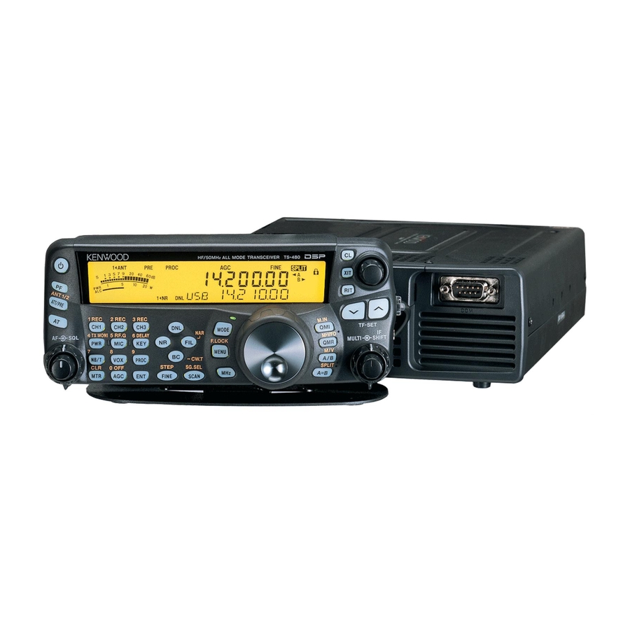
HF / 50MHz ALL MODE TRANSCEIVER
TS-480HX/480SAT
SERVICE MANUAL
Panel assy
(A62-1076-03)
Knob
Key top
(K29-9267-03)
(K29-9263-02)
Knob
(K29-9266-03)
DISASSEMBLY FOR REPAIR .................................. 2
CIRCUIT DESCRIPTION ........................................... 3
COMPONENTS DESCRIPTION ............................. 14
SEMICONDUCTOR DATA ..................................... 20
PARTS LIST ............................................................ 27
EXPLODED VIEW ................................................... 50
PACKING ................................................................ 54
ADJUSTMENT ....................................................... 55
INTERCONNECTION DIAGRAM ........................... 76
PC BOARD / SCHEMATIC DIAGRAM
RF UNIT (X44-327X-XX) .................................... 78
FINAL UNIT (X45-365X-XX) (A/3) ..................... 86
FINAL UNIT (X45-365X-XX) (B/3) ..................... 93
Microphone
(T91-0638-05)
Knob ring
(K29-9264-04)
Stand
Knob (Main dial)
(J09-0409-03)
(K21-1105-03)
CONTENTS
TERMINAL FUNCTION ........................................ 129
BLOCK DIAGRAM ................................................ 134
LEVEL DIAGRAM ................................................. 136
ACCESSORIES ..................................................... 140
SPECIFICATIONS ................................................. 141
© 2003-11 PRINTED IN JAPAN
B51-8667-00 ( N ) 694
Cabinet (Upper)
(A01-2189-02)
Knob
Panel
(K29-9265-03)
(A62-1079-01)
Knob
Foot
(K29-9270-03)
(J02-0441-05) x 4
Knob
(K29-9267-03)
FINAL UNIT (X45-365X-XX) (C/3) ..................... 96
FINAL UNIT (X45-366X-XX) (A/3) ..................... 98
FINAL UNIT (X45-366X-XX) (B/3) ................... 105
FINAL UNIT (X45-366X-XX) (C/3) ................... 108
DISPLAY UNIT (X54-3410-00) (A/3, B/3, C/3) ....... 110
TX-RX UNIT (X57-663X-XX) (A/2, B/2) .......... 116
SUB UNIT (X58-4900-XX) ................................ 128
Cabinet (Lower)
(A01-2190-02)
Advertisement
Chapters
Table of Contents

Related Manuals for Kenwood TS-480HX


Summary of Contents for Kenwood TS-480HX
-
Page 1: Table Of Contents
HF / 50MHz ALL MODE TRANSCEIVER TS-480HX/480SAT SERVICE MANUAL © 2003-11 PRINTED IN JAPAN B51-8667-00 ( N ) 694 Microphone Cabinet (Upper) (T91-0638-05) (A01-2189-02) Panel assy Knob Panel (A62-1076-03) (K29-9265-03) (A62-1079-01) Knob Key top Knob ring Knob Foot (K29-9267-03) (K29-9270-03) -
Page 2: Disassembly For Repair
TS-480HX/480SAT DISASSEMBLY FOR REPAIR How to remove the torque changeover le- Cautions for mounting the main dial knob ver (G02-0898-04) (K21-1105-03) 1. Turn the lever section of the torque changeover lever to Confirm that the lever section of the torque changeover the right. -
Page 3: Circuit Description
TS-480HX/480SAT CIRCUIT DESCRIPTION Frequency Configuration Figure. 1 shows the frequency configuration of this trans- ceiver. All modes operate in a double conversion while trans- mitting. FM mode operates in a triple conversion and other modes operate in a double conversion while receiving. - Page 4 TS-480HX/480SAT CIRCUIT DESCRIPTION ■ CAR (carrier) The 10.695MHz used in the local oscillation and detection is generated by the DDS (IC2). The output signal sent from this DDS passes through a buffer amplifier (Q10) and a low- pass filter, and is then sent to each signal.
-
Page 5: Receiver Circuit
TS-480HX/480SAT CIRCUIT DESCRIPTION DDS AD9835BRU (IC2) CW-R Filter offset 1 +1.5k +1.5k -1.5k -1.5k +(1.5k-PITCH) +(1.5k-PITCH) -(1.5k-PITCH) -(1.5k-PITCH) Filter offset 2 +0.71k +0.71k -0.71k -0.71k CW piitch +(PIITCH) -(PIITCH) +(PIITCH) FSK tone IF Shift +(IF S) -(IF S) +(IF S) - Page 6 TS-480HX/480SAT CIRCUIT DESCRIPTION ■ From receiving 1st mixer to the second IF fre- the transmit signal by passing the narrow-band MCF. It also reduces spurious components of the receive signal. quency (10.695MHz) TP1 (CN152) and TP2 (CN252) adjust MCF. The signal...
- Page 7 TS-480HX/480SAT CIRCUIT DESCRIPTION TX-RX unit D932 RF unit TX-RX unit (A/2) D940 (B/2) through FM IF Filter section 10.695MHz D932 XF931 D941 D934 AM 6kHz Q901 Q971 IF AMP XF932 IF AMP D931 D936 RX OUT 2nd IF 10.695MHz NB IN SSB/CW/FSK 2.4kHz...
- Page 8 TS-480HX/480SAT CIRCUIT DESCRIPTION ■ From detection to AF output ■ From the MIC terminal to modulation output As for the AF signal detected in each mode, a necessary The frequency configuration of the transmitting part is mode for the signal is selected by the analog switch (IC733).
- Page 9 TS-480HX/480SAT CIRCUIT DESCRIPTION 3) Recording a message 2) Playback The signal sent from the microphone is output from pin 11 The output signal (VOI) sent from the optional unit (VGS-1) to pin 10 of the analog switch (IC219), where it enters into passes from pin 1 to pin 2 of the DAC.
- Page 10 TS-480HX/480SAT CIRCUIT DESCRIPTION 2) FM mode D938 D934 D941 D932 TX IF IN XF931 Although the circuit directly modulating the frequency of 10.695MHz BW : 6kHz the VCO and the crystal oscillator was conventionally used, this transceiver uses a phase modulation circuit.
- Page 11 TS-480HX/480SAT CIRCUIT DESCRIPTION ■ From the drive output to antenna antenna tuner, the voltage detection circuit, the IN/ THROUGH changeover relay of the antenna tuner, transmis- The transmit signal sent from CN1 of the RF unit (X44-327) sion/ reception changeover relay, and the antenna...
- Page 12 TS-480HX/480SAT CIRCUIT DESCRIPTION Final AMP Sub unit Drive AMP Pre drive AMP DRV IN Q804 Drive AMP Q805 Final unit (A/3) ANT2 ANT1 K501 TX LPF L502 1.8~50MHz band K502 Final unit (B/3) Final unit (C/3) (RF unit) LPF section ANT section Fig.
- Page 13 TS-480HX/480SAT CIRCUIT DESCRIPTION ■ Around the main microcomputer The comparison voltage changes by changing the transmit output on the panel. Although the transmit power control The main microcomputer operates at 3.3V of the supply was conventionally performed with the hardware control us- voltage and 22.1184MHz of the clock frequency.
-
Page 14: Components Description
TS-480HX/480SAT COMPONENTS DESCRIPTION RF Unit (X44-327X-XX) Ref No. Use / Function Operation / Condition / Compatibility Ref No. Use / Function Operation / Condition / Compatibility Q10: Hi when ATT is ON. Switching ATT changeover relay control Q11: Hi when preamplifier is ON. - Page 15 ON when receiving preamplifier is OFF Ref No. Use / Function Operation / Condition / Compatibility D152 Switching 1/2: ON when receiving preamplifier is OFF D100 Backlight for KENWOOD logo 2/2: ON when receiving preamplifier is ON D101 Surge absorption Relay (K102) D154 Switching...
- Page 16 D10~13 LCD backlight Final Unit (X45-366X-XX) (B/3) Lights during transmission Ref No. Use / Function Operation / Condition / Compatibility Lights during reception D100 Backlight for KENWOOD logo D16~36 Backlight D101 Surge absorption Relay (K102) Reset circuit D151 Surge absorption...
- Page 17 TS-480HX/480SAT COMPONENTS DESCRIPTION Ref No. Use / Function Operation / Condition / Compatibility Ref No. Use / Function Operation / Condition / Compatibility Doubler 31.2MHz x 2 Q557 Buffer Output buffer for AM detection signal Switching LO1 filter cutoff changeover control...
- Page 18 TS-480HX/480SAT COMPONENTS DESCRIPTION Ref No. Use / Function Operation / Condition / Compatibility Ref No. Use / Function Operation / Condition / Compatibility IC213 3.3V AVR Q4: Hi when the 1.8kHz option filter is IC214 Filter amplifier CODEC output signal selected.
- Page 19 TS-480HX/480SAT COMPONENTS DESCRIPTION Ref No. Use / Function Operation / Condition / Compatibility Ref No. Use / Function Operation / Condition / Compatibility D212 18V Zener diode Voltage shift D810 Voltage shift D213 Reverse current D811~813 Reverse current prevention prevention...
-
Page 20: Semiconductor Data
TS-480HX/480SAT SEMICONDUCTOR DATA Main Microcomputer : HD64F2338VFC25 (TX-RX Unit IC204) Pin No. Name Function Pin No. Name Function CODEC input (VGS-1 playback) change- Reduced voltage detection interrupt over instruction H : VGS-1 playback H→L : Interrupt CODEC input (PKD) changeover instruc-... - Page 21 TS-480HX/480SAT SEMICONDUCTOR DATA Pin No. Name Function Pin No. Name Function VGS-1 enable TYPY Function detection 2 Amplitude comparison detection instruction VGS-1 reset signal L→H : Reset Phase comparison detection instruction RF serial parallel enable AVcc Power supply voltage 3.3V...
- Page 22 TS-480HX/480SAT SEMICONDUCTOR DATA Panel Microcomputer : 30622M8A-7N0GP (Display Unit IC3) Pin No. Name Function Pin No. Name Function Key illumination LED control signal Not used P93~P90 Dimmer output 3~0 CTS0 Not used BYTE Single chip mode selection (Vss connection) 37~44...
- Page 23 TS-480HX/480SAT SEMICONDUCTOR DATA Extended I/O Port ■ RF unit Pin No. Port name Pin name Function Active level Condition IC301 : BU2099FV (Shift register) BPF4 4.10~7.50MHz BPF When BPF is selected BPF5 7.50~10.5MHz BPF When BPF is selected BPF6 10.5~14.5MHz BPF...
- Page 24 TS-480HX/480SAT SEMICONDUCTOR DATA Pin No. Port name Pin name Function Active level Condition IC803 : UPD6345GS (Extended I/O), Enable : FEN1, 100W only CI (1) 25p capacitor switching Phase error correction C1 On : Active, Off : Inactive CI (2)
- Page 25 TS-480HX/480SAT SEMICONDUCTOR DATA Pin No. Port name Pin name Function Active level Condition IC212 : M62364FP (A/D) IEN3 VIN1 VGS-1 playback signal input Uses only to playback VGS-1. VOUT1 VGS-1 playback signal output Uses only to playback VGS-1. VOUT2 VIN2...
- Page 26 TS-480HX/480SAT SEMICONDUCTOR DATA CODEC : AK4550VT (TX-RX Unit IC217) ■ Block diagram ■ Pin function Name Function ∆Σ Decimation Clock VCOM Common voltage output, 0.45 x VDD AINL MCLK modulator filter divider AINR Rch analog input LRCK ∆Σ Decimation AINR...
-
Page 27: Parts List
K01-0420-05 HANDLE EH,ES ✽ ✽ 3C,3E F09-0478-05 FAN MOTOR K21-1105-03 KNOB (MAIN DIAL) ✽ ✽ 2D,2F F10-2450-02 SHIELDING COVER (X45 A/3) K29-9263-02 KEY TOP KH : TS-480HX (K) KS : TS-480SAT (K) EH : TS-480HX (E) ES : TS-480SAT (E) - Page 28 CK73FB1H102K CHIP C 1000PF ✽ C90-4111-05 ELECTRO 470UF 16WV C128 CC73FCH1H222J CHIP C 2200PF CC73GCH1H180J CHIP C 18PF C129,130 CC73GCH1H090B CHIP C 9.0PF EH,ES KH : TS-480HX (K) KS : TS-480SAT (K) EH : TS-480HX (E) ES : TS-480SAT (E)
- Page 29 CK73GB1H102K CHIP C 1000PF ✽ C281 CC73GCH1H010B CHIP C 1.0PF L41-6885-09 SMALL FIXED INDUCTOR ✽ C282 CK73GB1H103K CHIP C 0.010UF L41-1895-09 SMALL FIXED INDUCTOR KH : TS-480HX (K) KS : TS-480SAT (K) EH : TS-480HX (E) ES : TS-480SAT (E)
- Page 30 0 OHM J 1/16W RK73GB1J681J CHIP R 1/16W RK73GB1J103J CHIP R 1/16W R258 RK73GB1J471J CHIP R 1/16W RK73GB1J333J CHIP R 1/16W R259 RK73GB1J331J CHIP R 1/16W KH : TS-480HX (K) KS : TS-480SAT (K) EH : TS-480HX (E) ES : TS-480SAT (E)
- Page 31 CHIP C 10PF C91-2691-05 CERAMIC 470PF 250WV D253 MA2S111 DIODE D254 RN731V DIODE CE04EW1E471M ELECTRO 470UF 25WV D255 DAN235E DIODE CK73FB1E104K CHIP C 0.10UF KH : TS-480HX (K) KS : TS-480SAT (K) EH : TS-480HX (E) ES : TS-480SAT (E)
- Page 32 0.10UF C259 CC45FSL2H271J CERAMIC 270PF C260 CK73FB1H103K CHIP C 0.010UF C816-821 CK73FB1H103K CHIP C 0.010UF C304 CC45FSL2H181J CERAMIC 180PF C822 CK73FB1E104K CHIP C 0.10UF KH : TS-480HX (K) KS : TS-480SAT (K) EH : TS-480HX (E) ES : TS-480SAT (E)
- Page 33 L812 L40-4705-34 SMALL FIXED INDUCTOR (47UH) L40-1001-12 SMALL FIXED INDUCTOR L813 L34-4490-05 AIR-CORE COIL ✽ L39-1491-15 TOROIDAL COIL L814 L40-4705-34 SMALL FIXED INDUCTOR (47UH) KH : TS-480HX (K) KS : TS-480SAT (K) EH : TS-480HX (E) ES : TS-480SAT (E)
- Page 34 MOS IC R506,507 RK73FB2A101J CHIP R 1/10W R508,509 RK73FB2A102J CHIP R 1.0K 1/10W IC804,805 TC7WT125FU MOS IC R510,511 RK73FB2A101J CHIP R 1/10W 2SK2596 2SK2595 KH : TS-480HX (K) KS : TS-480SAT (K) EH : TS-480HX (E) ES : TS-480SAT (E)
- Page 35 CK73FB1H103K CHIP C 0.010UF CK45FB1H103K CERAMIC 0.010UF CK73FB1E104K CHIP C 0.10UF C402 CC45FSL2H151J CERAMIC 150PF CK73FB1H103K CHIP C 0.010UF C403 C93-0570-05 CHIP C 68PF KH : TS-480HX (K) KS : TS-480SAT (K) EH : TS-480HX (E) ES : TS-480SAT (E)
- Page 36 SMALL FIXED INDUCTOR (47UH) C838 CE04CW1E100M ELECTRO 10UF 25WV C839,840 CK45FB1H103K CERAMIC 0.01UF L202 L39-0463-05 TOROIDAL COIL C841 C93-0553-05 CHIP C 3.0PF L203,204 L39-1440-05 TOROIDAL COIL KH : TS-480HX (K) KS : TS-480SAT (K) EH : TS-480HX (E) ES : TS-480SAT (E)
- Page 37 R12-6737-05 TRIMMING POT. (3.3K) RK73FB2A102J CHIP R 1.0K 1/10W VR801 R12-6737-05 TRIMMING POT. (3.3K) R23,24 RK73FB2A470J CHIP R 1/10W VR802 R12-6744-05 TRIMMING POT. (47K) KH : TS-480HX (K) KS : TS-480SAT (K) EH : TS-480HX (E) ES : TS-480SAT (E)
- Page 38 CHIP R 0 OHM J 1/16W ✽ D1-4 B30-2270-05 LED (YELLOW) RK73GB1J103J CHIP R 1/16W ✽ D10-13 B30-2270-05 LED (YELLOW) RK73FB2A271J CHIP R 1/10W KH : TS-480HX (K) KS : TS-480SAT (K) EH : TS-480HX (E) ES : TS-480SAT (E)
- Page 39 C92-0628-05 CHIP-TAN 10UF 10WV CC73GCH1H470J CHIP C 47PF CK73GB1C473K CHIP C 0.047UF CK73GB1H472K CHIP C 4700PF CK73GB1H103K CHIP C 0.010UF CK73GB1H102K CHIP C 1000PF KH : TS-480HX (K) KS : TS-480SAT (K) EH : TS-480HX (E) ES : TS-480SAT (E)
- Page 40 CC73GCH1H220J CHIP C 22PF C229,230 CK73GB1H103K CHIP C 0.010UF C307 CK73GB1C104K CHIP C 0.10UF C232-237 CK73GB1H103K CHIP C 0.010UF C308 CK73GB1H102K CHIP C 1000PF KH : TS-480HX (K) KS : TS-480SAT (K) EH : TS-480HX (E) ES : TS-480SAT (E)
- Page 41 CK73GB1H102K CHIP C 1000PF C472 CK73GB1H472K CHIP C 4700PF C584 CC73GCH1H470J CHIP C 47PF C473 CC73GCH1H470J CHIP C 47PF C585,586 CK73GB1C104K CHIP C 0.10UF KH : TS-480HX (K) KS : TS-480SAT (K) EH : TS-480HX (E) ES : TS-480SAT (E)
- Page 42 ELECTRO 470UF 16WV ✽ C753 CK73FB1E104K CHIP C 0.10UF CN390 E40-6357-05 PIN ASSY ✽ C754 C90-4114-05 ELECTRO 470UF 16WV CN403 E40-5978-05 FLAT CABLE CONNECTOR KH : TS-480HX (K) KS : TS-480SAT (K) EH : TS-480HX (E) ES : TS-480SAT (E)
- Page 43 1/16W L211 L40-4705-34 SMALL FIXED INDUCTOR (47UH) L212 L40-1015-34 SMALL FIXED INDUCTOR (100UH) CP208 RK75GA1J101J CHIP-COM 100 1/16W ✽ L217 L41-1005-27 SMALL FIXED INDUCTOR KH : TS-480HX (K) KS : TS-480SAT (K) EH : TS-480HX (E) ES : TS-480SAT (E)
- Page 44 CHIP R 1/16W RK73GB1J100J CHIP R 1/16W R135 RK73GB1J101J CHIP R 1/16W R92-1252-05 CHIP R 0 OHM J 1/16W R136 RK73GB1J123J CHIP R 1/16W KH : TS-480HX (K) KS : TS-480SAT (K) EH : TS-480HX (E) ES : TS-480SAT (E)
- Page 45 CHIP R 1/16W R283,284 RK73GB1J104J CHIP R 100K 1/16W R501 RK73GB1J101J CHIP R 1/16W R285 RK73GB1J101J CHIP R 1/16W R502 RK73GB1J104J CHIP R 100K 1/16W KH : TS-480HX (K) KS : TS-480SAT (K) EH : TS-480HX (E) ES : TS-480SAT (E)
- Page 46 100K 1/16W R591 RK73GB1J274J CHIP R 270K 1/16W R690 RK73GB1J103J CHIP R 1/16W R592 RK73GB1J331J CHIP R 1/16W R691 RK73GB1J102J CHIP R 1.0K 1/16W KH : TS-480HX (K) KS : TS-480SAT (K) EH : TS-480HX (E) ES : TS-480SAT (E)
- Page 47 R802 RK73GB1J101J CHIP R 1/16W R918 R92-1252-05 CHIP R 0 OHM J 1/16W R803 RK73GB1J333J CHIP R 1/16W R919 RK73GB1J102J CHIP R 1.0K 1/16W KH : TS-480HX (K) KS : TS-480SAT (K) EH : TS-480HX (E) ES : TS-480SAT (E)
- Page 48 MOS IC D213 RLS245 DIODE ✽ D351,352 KDZ18EV ZENER DIODE KH,EH IC216 XC62FP1802P MOS IC ✽ D352 KDZ18EV ZENER DIODE KS,ES IC217 AK4550VT MOS IC KH : TS-480HX (K) KS : TS-480SAT (K) EH : TS-480HX (E) ES : TS-480SAT (E)
- Page 49 CHIP R 1/10W KH,EH Q503 2SK1824 D1,2 1SS388 DIODE Q504-506 2SC4617(Q) TRANSISTOR Q1,2 2SK3075-H Q507 KRA302E DIGITAL TRANSISTOR Q508 2SC4617(R) TRANSISTOR ✽ Q551 3SK317 KH : TS-480HX (K) KS : TS-480SAT (K) EH : TS-480HX (E) ES : TS-480SAT (E)
-
Page 50: Exploded View
TS-480HX/480SAT EXPLODED VIEW (MAIN BODY UPPER SIDE) D M2.6 x 6 (OC) BLK : N33-2606-45 L M2.6 x 8 (Br-Tap) : N87-2608-46 Lx12 77x2 Final unit (B/3) Lx11 Final unit (C/3) TX-RX unit (B/2) TX-RX unit (A/2) Parts with the exploded numbers larger than 700 are not supplied. - Page 51 TS-480HX/480SAT EXPLODED VIEW (MAIN BODY LOWER SIDE) : TS-480SAT B ø4 (FW) : N15-1040-46 D M2.6 x 6 (OC) BLK : N33-2606-45 E M3 x 14 (Bi) BLK : N35-3014-45 F M4 x 10 (Bi) : N35-4010-46 G M3 x 20 BLK : N66-3020-45 H M2.6 x 8...
- Page 52 TS-480HX/480SAT EXPLODED VIEW (MAIN BODY LOWER SIDE) : TS-480HX B ø4 (FW) : N15-1040-46 D M2.6 x 6 (OC) BLK : N33-2606-45 F M4 x 10 (Bi) : N35-4010-46 G M3 x 20 BLK : N66-3020-45 H M2.6 x 8 : N67-2608-46 L M2.6 x8 (Br-Tap)
- Page 53 TS-480HX/480SAT EXPLODED VIEW (PANEL) Bottom Front 203 x2 Rear Right Side Display unit (B/3) Green Front Rear Blue Right Side Display unit (C/3) Display unit (A/3) : N14-0582-14 : N19-0670-05 J M2 x 16 : N80-2016-45 K M2.6 x 5 : N82-2605-46...
-
Page 54: Packing
TS-480HX/480SAT PACKING 44 DIN plug (6P) 73 Sheet (G11-4269-04) x 4 (E57-0404-05) 90 Protection bag (H25-2327-04) Sheet (G11-4228-04) 96 Stand (J09-0409-03) Protection bag (H25-2343-04) 80 Cushion (G13-2022-14) 101 Bracket (J29-0707-03) 91 Protection bag (H25-2343-04) Protection bag 98 Bracket (J29-0663-13) (H25-2343-04) -
Page 55: Adjustment
1) Current range : 100mA, 1.5A, 15A, high-precision am- 2) Dissipation : 150W or greater meter may be used. 250W or greater (TS-480HX) 3. RF VTVM (RF V.M) 13. Linear Detector 1) Input impedance : 1MΩ and less than 3pF, min. - Page 56 0 OFF FINE SCAN EXT.SP DATA REMOTE PANEL • Rear panel PADDLE • Rear panel (TS-480SAT) Service Jig A. Coaxial cable (E37-0620-05), about 37cm • Rear panel (TS-480HX) B. Flat cable (12P) (E37-1129-08), about 15cm C. Data terminal short plug (W05-0611-00)
- Page 57 TS-480HX/480SAT ADJUSTMENT ■ How to use the coaxial cable and the flat cable 1. Remove the three coaxial cables ( q, w, e ) from their respective connectors on the TX-RX unit (A/2) and the RF unit. 2. Remove the flat cable ( r ) from its connectors on the TX- RX unit (A/2) and the final unit (C/3).
-
Page 58: Updating Firmware
TS-480HX/480SAT ADJUSTMENT ware appears on the 7 segment display while the [M- Updating the Firmware CHKSUM] appears on the 13 segment display.) ■ System requirements 18. Turn the transceiver OFF. • PC (Windows 95/ 98/ 98SE/ Me/ NT 4.0/ 2000/ XP) S201 •... -
Page 59: Adjustment Mode Menu
TS-480HX/480SAT ADJUSTMENT Adjustment Mode Menu (Menu No. 00~78) Adjustment Item Apply 100W Apply 200W Display Item Frequency Mode IF SHIFT VR IF.CENTR Center 14.2M AGC Ref. AGC REF Referense 14.2M HF IF Gain HF. GAIN AGC Start 14.2M HF SSB S-Meter HF.SSB S1... - Page 60 TS-480HX/480SAT ADJUSTMENT Adjustment Item Apply 100W Apply 200W Display Item Frequency Mode TGC 10M 2.TGC 10M 200W 10.1M TGC 14M 2.TGC 14M 200W 14.1M TGC 18M 2.TGC 18M 200W 18.1M TGC 21M 2.TGC 21M 200W 21.1M TGC 24.9M 2.TGC 24M 200W 24.9M...
- Page 61 Method equipment 1. Setting and 1) Connect the DC cord to the full reset DC power supply. • TS-480HX DC IN1 and DC IN2 : DC 13.8V • TS-480SAT DC IN1 : DC 13.8V 2) Full reset Remote LCD After displaying Display should be normal.
- Page 62 TS-480HX/480SAT ADJUSTMENT Receiver Section Measurement Adjustment Item Condition Specifications/Remarks Test- Unit Terminal Unit Parts Method equipment • Perform the following in the adjustment mode. Item 1, 4, 6 and 10~17. To terminate the adjustment menu in the middle, save your settings with Menu No. 76.
- Page 63 TS-480HX/480SAT ADJUSTMENT Measurement Adjustment Item Condition Specifications/Remarks Test- Unit Terminal Unit Parts Method equipment 7. FM 1) Display f. : 29.200MHz TX/RX ANT1 TX-RX L551 AF distortion min. 1.4% or less discriminator Mode : FM unit rear (A/2) AF output : 0.63V/8Ω...
- Page 64 TS-480HX/480SAT ADJUSTMENT Measurement Adjustment Item Condition Specifications/Remarks Test- Unit Terminal Unit Parts Method equipment • 52.2MHz 11) Display f. : 52.200MHz TX/RX ANT1 Check 12dB SINAD or more Mode : FM unit rear PRE-AMP : ON panel AF output : 0.63V/8Ω...
- Page 65 TS-480HX/480SAT ADJUSTMENT Measurement Adjustment Item Condition Specifications/Remarks Test- Unit Terminal Unit Parts Method equipment 15. HF FM SQL 1) Menu No. : 09 TX/RX ANT1 Remote [ ] or 1 push thigh (29.2MHz, FM) unit rear control [ ] SSG f. : 29.200MHz...
- Page 66 TS-480HX/480SAT ADJUSTMENT Transmitter Section (TS-480HX) Measurement Adjustment Item Condition Specifications/Remarks Test- Unit Terminal Unit Parts Method equipment 1. Final idling 1) Display f. : 14.100MHz Ammeter TX/RX DC IN1 Final Check the default current Mode : USB unit rear DC IN2...
- Page 67 TS-480HX/480SAT ADJUSTMENT Measurement Adjustment Item Condition Specifications/Remarks Test- Unit Terminal Unit Parts Method equipment 7. Band 2TGC 1) Menu No. : 41 Power meter TX/RX ANT1 Remote [ ] or The Band 2TGC 200W± 10W (HF) (1.83MHz, USB) 250W ATT unit rear...
- Page 68 TS-480HX/480SAT ADJUSTMENT Measurement Adjustment Item Condition Specifications/Remarks Test- Unit Terminal Unit Parts Method equipment • 10W 4) Menu No. : 63 Power meter TX/RX ANT1 Remote [ ] or Set the adjustment 12.5W± 0.5W (14.1MHz, USB) 250W ATT unit rear...
- Page 69 TS-480HX/480SAT ADJUSTMENT Measurement Adjustment Item Condition Specifications/Remarks Test- Unit Terminal Unit Parts Method equipment 16. Current 1) Menu No. : 68 Power meter TX/RX ANT1 Remote [ ] or Set the adjustment 220W± 5W protection (3.51MHz, USB) 250W ATT unit rear...
- Page 70 TS-480HX/480SAT ADJUSTMENT Measurement Adjustment Item Condition Specifications/Remarks Test- Unit Terminal Unit Parts Method equipment 4. Drive output 1) Menu No. : 19 Spectrum RF Check 3dBm or more level (14.1MHz, USB) analyzer (DRV) Disconnect the cable from CN1 and insert a cable from the spectrum analyzer.
- Page 71 TS-480HX/480SAT ADJUSTMENT Measurement Adjustment Item Condition Specifications/Remarks Test- Unit Terminal Unit Parts Method equipment • 18M 7) Menu No. : 36 Power meter TX/RX ANT1 Remote [ ] or The Band TGC 100W± 5.0W (18.1MHz, USB) 150W ATT unit rear...
- Page 72 TS-480HX/480SAT ADJUSTMENT Measurement Adjustment Item Condition Specifications/Remarks Test- Unit Terminal Unit Parts Method equipment 14. AM carrier 1) Menu No. : 55 Power meter TX/RX ANT1 Check for ALC 1 dot or more level (14.1MHz, AM) 150W ATT unit rear meter.
- Page 73 TS-480HX/480SAT ADJUSTMENT Adjustment Points (Upper Side) TC501 VR501 FINAL UNIT (C/3) : TS-480HX TC501 : Null TC501 FINAL UNIT (C/3) : TS-480SAT VR501 : TX power VR502 : AT detection balance TC501 : Null TS-480SAT TS-480HX VR502 FINAL UNIT FINAL UNIT...
- Page 74 TS-480HX/480SAT ADJUSTMENT Adjustment Points (Lower Side) : TS-480HX FINAL UNIT (X45-366) (A/3) VR802 VR801 RF UNIT (X44-327) CN252 L166 L167 L168 TC51 TC52 CN152 FINAL UNIT (A/3) RF UNIT VR1,2,3,801 : Final idling current L166,167,168 : MCF (73.095MHz) VR802 : ODP (Over Drive Protection) TC51 : Trap frequency (11.7MHz)
- Page 75 TS-480HX/480SAT ADJUSTMENT Adjustment Points (Lower Side) : TS-480SAT RF UNIT FINAL UNIT (X44-327) (X45-365) (A/3) CN252 L166 L167 L168 TC51 TC52 CN152 FINAL UNIT (A/3) RF UNIT VR1,2,3 : Final idling current L166,167,168 : MCF (73.095MHz) TC51 : Trap frequency (11.7MHz) FRONT TC52 : Trap frequency (15.5MHz)
-
Page 76: Interconnection Diagram
E37-1069-05 DASH J301 J302 FINAL UNIT (FILTER) CKYS X45-365X-XX (B/3) [AT] PRES RF UNIT DATA 0-11:TS-480SAT (K) X44-327X-XX 2-71:TS-480SAT (E) 0-00:TS-480HX/480SAT (K) X45-366X-XX (B/3) [200W] 2-71:TS-480HX/480SAT (E) 0-00:TS-480HX (K) 2-71:TS-480HX (E) CN254 (RED) E04-0154-05 E37-1060-05 CN153 (BLUE) E04-0154-05 E37-1061-05 CN253... - Page 77 PRES DATA B38-0879-05 E37-1058-05 CN501 E04-0191-05 W501 W502 E04-0191-05 DISPLAY UNIT E04-0191-05 X54-3410-00(A/3) TX-RX UNIT X57-663X-XX (A/2) 0-11:TS-480HX (K) 0-12:TS-480SAT (K) J202 2-71:TS-480HX (E) E58-0506-05 E58-0506-05 RIT/XIT ENC. 2-72:TS-480SAT (E) W02-3662-05 CN375 E40-5758-05 MULUT ENC. /IF SHIFT VR DATA X54-3410-00(C/3)
- Page 78 J351 FINAL UNIT (FILTER) CKYS CKYS X45-365X-XX (B/3) [AT] RF UNIT PRES PRES DATA DATA 0-11:TS-480SAT (K) X44-327X-XX 2-71:TS-480SAT (E) 0-00:TS-480HX/480SAT (K) X45-366X-XX (B/3) [200W] 2-71:TS-480HX/480SAT (E) B38-0879-05 0-00:TS-480HX (K) E37-1058-05 2-71:TS-480HX (E) CN254 (RED) CN501 E04-0154-05 E04-0191-05 E37-1060-05 W501...
- Page 79 TS-480HX/480SAT PC BOARD RF UNIT (X44-327X-XX) 0-00 : KH,KS 2-71 : EH,ES Component side view (J72-0874-19) J72-0874-19 (BLK) DASH C151 D156 CKYS PRES C153 DATA R176 C169 L302 L303 PRES R194 C166 L305 R177 RATB R174 C170 C167 R204 C161...
- Page 80 TS-480HX/480SAT PC BOARD RF UNIT (X44-327X-XX) 0-00 : KH,KS 2-71 : EH,ES Component side view (J72-0874-19) CN254 C285 R282 IF 10.695MHz R194 L161 L165 (RED) R177 C170 R204 L164 R205 D256 C171 R184 C198 R178 L262 L264 CN153 L166 L167...
- Page 81 TS-480HX/480SAT TS-480HX/480SAT PC BOARD PC BOARD RF UNIT (X44-327X-XX) 0-00 : KH,KS 2-71 : EH,ES Component side view (J72-0874-19) J72-0874-19 (BLK) DASH C151 D156 CKYS PRES C153 DATA RF UNIT (X44-327X-XX) 0-00 : KH,KS 2-71 : EH,ES R176 C169 L302...
- Page 82 TS-480HX/480SAT PC BOARD RF UNIT (X44-327X-XX) 0-00 : KH,KS 2-71 : EH,ES Foil side view (J72-0874-19) R275 Q161 C267 Q160 R294 Q256 C270 R290 R183 D G2 L258 Q253 R182 Q156 Q157 D255 L255 R185 D252 C174 R288 Q252 C196...
- Page 83 TS-480HX/480SAT PC BOARD RF UNIT (X44-327X-XX) 0-00 : KH,KS 2-71 : EH,ES Foil side view (J72-0874-19) J72-0874-19 R191 Q158 1.8M C173 R152 R202 R156 L153 R165 R167 R168 Q160 R160 C200 Q156 3.5M R185 C174 R179 C176 L160 D251 R317...
- Page 84 TS-480HX/480SAT TS-480HX/480SAT PC BOARD PC BOARD RF UNIT (X44-327X-XX) 0-00 : KH,KS 2-71 : EH,ES Foil side view (J72-0874-19) J72-0874-19 R191 Q158 1.8M C173 R152 R202 R156 L153 R165 RF UNIT (X44-327X-XX) 0-00 : KH,KS 2-71 : EH,ES Foil side view (J72-0874-19)
-
Page 85: Schematic Diagram
TS-480HX/480SAT SCHEMATIC DIAGRAM RF UNIT (X44-327X-XX) 13.11V 13.19V CN52 7.64V HN7G01FU E18-0254-05 E40-5487-05 RATB NORM SWITCHING CN51 12.37V Q302 KRC402E E40-5487-05 RX POWER SUPPLY 0.17V CONTROL SWITCH E18-0254-05 SWITCHING E40-5487-05 HVC131 RAT(B) -115dBm -114dBm -114dBm SWITCHING FINAL UNIT(ANT) E04-0154-05 X45-365X-XX(C/3)[AT]... - Page 86 TS-480HX/480SAT SCHEMATIC DIAGRAM RF UNIT (X44-327X-XX) RATB RATB SWITCHING 1000u 220p HVC131 6.8u 6.8u KRA318E 13.00V 13.02V BPF1 30K~1.705M SWITCHING SWITCHING HSC277 6.8u KRA318E 1200p RN731V 13.00V SWITCHING 13.02V 1.8M 1.705~2.5M BPF2 SWITCHING SWITCHING HSC277 SWITCHING 5.6u KRA318E 470p 13.00V 13.02V...
- Page 87 TS-480HX/480SAT SCHEMATIC DIAGRAM RF UNIT (X44-327X-XX) RATB RATB SWITCHING Q152 RN47A5 12.63V BPF WAVE-FORM Q156,157 RX 1st MIXER 1st MIXER 4.30V Q160 Q156 Q151 R177 SWITCHING 0.02V 2SK520(K44) 2SK520(K44) KRC402E L158 L39-1476-05 R182 R186 C170 -101.5dBm 0.1u D152 L155 L156 2.47V...
- Page 88 TS-480HX/480SAT SCHEMATIC DIAGRAM RF UNIT (X44-327X-XX) MCF(B) CN152 E40-0211-05 SWITCHING MCF WAVE-FORM ALIGNMENT D155 73.095M MCF DAN235E L166 L168 XF151 L34-4408-05 L34-4408-05 L71-0605-05 -101dBm L167 L34-4408-05 SWITCHING LO1(B) D154 DAN235E CN153 TX-RX UNIT E04-0154-05 C192 X57-663X-XX(A/2) R196 0.01u MCF(B) MCF WAVE-FORM...
- Page 89 L302 X57-663X-XX(A/2) L303 L304 L305 GND TP for JIG CKYS CKYS CKYS CKYS CKYS CKYS X44-327X-XX TC51 TC52 C129 C130 PRE GAIN PRE GAIN PRE GAIN PRE GAIN PRE GAIN PRE GAIN 0-00 TS-480HX/480SAT 2-71 TS-480HX/480SAT C05-0385-05 C05-0385-05 6.8u 6.8u...
- Page 90 TS-480HX/480SAT PC BOARD 100W FINAL UNIT (X45-365X-XX) (A/3) 0-11 : KS 2-71 : ES Component side view (J72-0875-09) CN13 CN12 DIN1 DOUT1 DOUT2 DIN2 L804 C805 L801 K809 K811 D801 D804 D805 D806 D807 D808 D891 D802 D803 L802 K801...
-
Page 91: Final Unit (X45-365X-Xx) (A/3)
TS-480HX/480SAT PC BOARD 100W FINAL UNIT (X45-365X-XX) (A/3) 0-11 : KS 2-71 : ES Component side view (J72-0875-09) Ref. No. Address BLACK IC801 IC802 IC803 IC804 IC805 FAN1– FAN1+ Q891 D801 D802 D803 D804 D805 D806 D807 D808 K817 K819... - Page 92 TS-480HX/480SAT TS-480HX/480SAT PC BOARD PC BOARD 100W FINAL UNIT (X45-365X-XX) (A/3) 0-11 : KS 2-71 : ES 100W FINAL UNIT (X45-365X-XX) (A/3) Component side view (J72-0875-09) 0-11 : KS 2-71 : ES Component side view (J72-0875-09) CN13 Ref. No. Address...
- Page 93 TS-480HX/480SAT PC BOARD 100W FINAL UNIT (X45-365X-XX) (A/3) 0-11 : KS 2-71 : ES Foil side view (J72-0875-09) D815 C873 C865 L833 L831 C857 L835 C879 C834 C851 C846 L823 L827 L826 D819 D817 D821 L838 C885 D810 D813 D812...
- Page 94 TS-480HX/480SAT PC BOARD 100W FINAL UNIT (X45-365X-XX) (A/3) 0-11 : KS 2-71 : ES Foil side view (J72-0875-09) Ref. No. Address D809 D810 D811 D812 D813 D814 D815 D816 D817 D818 D819 D820 D821 D822 D823 D824 C894 C893 C815...
- Page 95 TS-480HX/480SAT TS-480HX/480SAT PC BOARD PC BOARD 100W FINAL UNIT (X45-365X-XX) (A/3) 0-11 : KS 2-71 : ES 100W FINAL UNIT (X45-365X-XX) (A/3) 0-11 : KS 2-71 : ES Foil side view (J72-0875-09) Foil side view (J72-0875-09) Ref. No. Address D809...
- Page 96 TS-480HX/480SAT SCHEMATIC DIAGRAM FINAL UNIT (X45-365X-XX)(A/3)[AT] FANH FANH FANL FANL IC1+ IC1+ E40-3252-05 IC1- IC1- 14AF PCS1 PCS1 14AG SWITCHING TA7805F 4.97V 4.98V 4.98V 2SJ305 13.27V 3.47V 3.19V TA7808F DTC114EKA 7.91V 13.28V E40-3246-05 SWITCHING 14AT EXT.AT 5.6k F06-4027-05 DIN1 1.2k DIN2 0.1u...
- Page 97 TS-480HX/480SAT SCHEMATIC DIAGRAM FINAL UNIT (X45-365X-XX) (A/3) FANH FANH FANL FANL IC1+ IC1+ IC1- IC1- PCS1 PCS1 SUB UNIT (X58-4900-01) 330 1/4 T:13.28V 0.1u DRIVE AMP 2SK3075-H E40-5608-05 VOLTAGE T:0.01V SHIFT DIN1 DIN1 DOUT1 L39-1491-15 L39-1485-05 L39-1434-05 0.1u 1000p DOUT2...
- Page 98 TS-480HX/480SAT SCHEMATIC DIAGRAM FINAL UNIT (X45-365X-XX) (A/3) FANH FANH FANL FANL IC1+ IC1+ IC1- IC1- SURGE ABSORPTION E40-3246-05 PCS1 FAN1- SWITCHING 3.19V FAN1+ DTC114EKA T:13.18V T:4.14V BIAS CONTROL T:0.73V T:13.16V 12.67V 2SC3421(Y) 12.68V T:13.19V SI7445DP D1,2 SWITCHING 2SD1757K TEMPERATURE COMPENSATION 2SD1757K T:1.41V...
- Page 99 FINAL UNIT (X45-365X-XX)(A/3)[AT] FANH FANH FANH FANH FANH FANH FANL FANL FANL FANL FANL FANL IC1+ IC1+ IC1+ IC1+ IC1+ IC1+ E40-3252-05 IC1- IC1- IC1- IC1- IC1- IC1- SURGE ABSORPTION 14AF E40-3246-05 PCS1 PCS1 PCS1 PCS1 PCS1 14AG FAN1- SWITCHING 3.19V FAN1+ DTC114EKA...
- Page 100 TS-480HX/480SAT SCHEMATIC DIAGRAM FINAL UNIT (FILTER) (X45-365X-XX)(B/3) [AT] 0-11:TS-480SAT(K) 2-71:TS-480SAT(E) L102 L103 K102 L39-1260-05 POUT L39-1259-05 K101 Land & Wire CN102 POUT C103 560p C107 120p R102 C104 C108 D101 1SS355 Land & Wire C111 0.01u L101 1.705~2.5 D101 Land & Wire...
- Page 101 TS-480HX/480SAT PC BOARD 100W FINAL UNIT (X45-365X-XX) (B/3) 0-11 : KS 2-71 : ES Component side view (J72-0875-09) CN102 L304 L302 J72-0875-09 B/3 K301 K302 K201 K202 K251 K252 K351 L353 L352 K352 K101 K102 C104 K401 L405 L404 L402...
- Page 102 TS-480HX/480SAT PC BOARD 100W FINAL UNIT (X45-365X-XX) (B/3) 0-11 : KS 2-71 : ES Foil side view (J72-0875-09) C309 C312 J72-0875-09 B/3 C212 C103 D451 C463 C461 W501 W506 W505 W504 W503 W502 Component side Ref No. Address Ref No. Address...
- Page 103 TS-480HX/480SAT PC BOARD 100W FINAL UNIT (X45-365X-XX) (C/3) 0-11 : KS 2-71 : ES Component side view (J72-0875-09) J72-0875-09 C/3 YELLOW Q505 CN504 ANT2 AT IN L508 D509 FEN2 K502 DATA D507 ANT1 CN501 K503 L507 R550 R530 D508 L501...
-
Page 104: Final Unit (X45-365X-Xx) (B/3)
TS-480HX/480SAT SCHEMATIC DIAGRAM FINAL UNIT (ANT)(X45-365X-XX)(C/3)[AT] 0-11:TS-480SAT(K) 2-71:TS-480SAT(E) C537 8p POUT Land & Wire CN503 K501 RF UNIT L502 W501 L505 L506 L511 POUT X44-327X-XX 150n K503 K502 S76-0424-05 S76-0424-05 Land & Wire D501 D502 1SS348 1SS348 R505 W502 L504... -
Page 105: Final Unit (X45-365X-Xx) (C/3)
TS-480HX/480SAT PC BOARD 200W FINAL UNIT (X45-366X-XX) (A/3) 0-00 : KH 2-71 : EH Component side view (J72-0876-09) CN13 CN12 DIN1 4 DOUT1 DOUT2 DIN2 C801 R805 VR802 C808 L802 C832 R826 C831 R825 D807 Q804 R838 C830 R824 C829... -
Page 106: Final Unit (X45-366X-Xx) (A/3)
TS-480HX/480SAT PC BOARD 200W FINAL UNIT (X45-366X-XX) (A/3) 0-00 : KH 2-71 : EH Component side view (J72-0876-09) Ref. No. Address BLACK FAN1– FAN1+ Q803 Q804 Q805 CN10 Q806 FAN2– FAN2+ D802 D803 D806 D807 L818 R816 C819 W801 J72-0876-09 A/3... - Page 107 TS-480HX/480SAT TS-480HX/480SAT PC BOARD PC BOARD 200W FINAL UNIT (X45-366X-XX) (A/3) 0-00 : KH 2-71 : EH 200W FINAL UNIT (X45-366X-XX) (A/3) Component side view (J72-0876-09) 0-00 : KH 2-71 : EH Component side view (J72-0876-09) CN13 Ref. No. Address...
-
Page 108: Final Unit (X45-366X-Xx) (B/3)
TS-480HX/480SAT PC BOARD 200W FINAL UNIT (X45-366X-XX) (A/3) 0-00 : KH 2-71 : EH Foil side view (J72-0876-09) J72-0876-09 A/3 C817 C837... -
Page 109: Final Unit (X45-366X-Xx) (C/3)
TS-480HX/480SAT PC BOARD 200W FINAL UNIT (X45-366X-XX) (A/3) 0-00 : KH 2-71 : EH Foil side view (J72-0876-09) Ref. No. Address Q807 R823 R804 C806 C824 C810 Component side C804 Layer 1 Q807 R814 Layer 2 R813 Foil side... -
Page 110: Ref. No. Address
TS-480HX/480SAT TS-480HX/480SAT PC BOARD PC BOARD 200W FINAL UNIT (X45-366X-XX) (A/3) 0-00 : KH 2-71 : EH 200W FINAL UNIT (X45-366X-XX) (A/3) 0-00 : KH 2-71 : EH Foil side view Foil side view (J72-0876-09) (J72-0876-09) Ref. No. Address Q807... - Page 111 TS-480HX/480SAT SCHEMATIC DIAGRAM FINAL UNIT (X45-366X-XX)(A/3)[200W] 0-00:TS-480HX(K) 2-71:TS-480HX(E) E40-3252-05 14AF FANH FANH 14AG FANL FANL IC1+ IC1+ IC1- IC1- PCS1 PCS1 TA7805F TA7808F 7.85V 4.94V 13.25V 13.25V E40-3246-05 14AT EXT.AT DIN1 0.1u T:12.75V T:13.21V PRE-DRIVE AMP DIN2 2SK2596 T:2.36V T:1.36V 0.1u...
- Page 112 TS-480HX/480SAT SCHEMATIC DIAGRAM FINAL UNIT (X45-366X-XX) (A/3) FANH FANH FANL FANL IC1+ IC1+ IC1- IC1- PCS1 PCS1 BIAS CONTROL T:0.71V T:7.81V 2SC3421(Y) SUB UNIT (X58-4900-00) 330 1/4W T:1.40V 13.28V 0.1u CN12 DRIVE AMP 2SK3075-H MA27-B 1/8W 3.3k E40-5608-05 VOLTAGE DIN1 0.01V...
- Page 113 TS-480HX/480SAT SCHEMATIC DIAGRAM FINAL UNIT (X45-366X-XX) (A/3) SURGE FANH FANH ABSORPTION E40-3246-05 FANL FANL IC1+ IC1- FAN1- PCS1 FAN1+ CN10 SWITCHING E40-3246-05 DTC114EKA FAN2- 3.25V FAN2+ 12.95V 12.95V SURGE ABSORPTION SWITCHING SWITCHING 2SD1757K 2SD1757K SWITCHING T:4.15V SI7445DP T:13.22V T:13.21V T:13.22V...
- Page 114 FINAL UNIT (X45-366X-XX)(A/3)[200W] 0-00:TS-480HX(K) 2-71:TS-480HX(E) E40-3252-05 14AF SURGE FANH FANH FANH FANH FANH FANH ABSORPTION 14AG E40-3246-05 FANL FANL FANL FANL FANL FANL IC1+ IC1+ IC1+ IC1+ IC1+ IC1- IC1- IC1- IC1- IC1- FAN1- PCS1 PCS1 PCS1 PCS1 PCS1 FAN1+...
- Page 115 TS-480HX/480SAT SCHEMATIC DIAGRAM FINAL UNIT (FILTER) (X45-366X-XX)(B/3) [200W] 0-00:TS-480HX(K) 2-71:TS-480HX(E) T68-2 T68-2 L103 L102 POUT K102 W101 K101 L39-1260-05 L39-1259-05 Land & Wire POUT R101 C107 120p C103 560p Land & Wire D101 1SS355 C104 C108 L101 C111 0.01u 1.705~2.5 Land &...
- Page 116 TS-480HX/480SAT PC BOARD 200W FINAL UNIT (X45-366X-XX) (B/3) 0-00 : KH 2-71 : EH Component side view (J72-0876-09) W101 L302 L304 J72-0876-09 B/3 K301 L202 K302 K201 K202 K251 K252 L353 L352 L354 K351 K352 K101 K102 C107 L405 K401...
-
Page 117: Component Side Layer
TS-480HX/480SAT PC BOARD 200W FINAL UNIT (X45-366X-XX) (B/3) 0-00 : KH 2-71 : EH Foil side view (J72-0876-09) C307 C308 J72-0876-09 B/3 C311 D301 C205 C315 C202 C212 C203 C204 D201 C254 C215 C357 C360 D351 C363 C108 D101 C111... -
Page 118: Layer 1
TS-480HX/480SAT PC BOARD 200W FINAL UNIT (X45-366X-XX) (C/3) 0-00 : KH 2-71 : EH Component side view (J72-0876-09) J72-0876-09 C/3 ANT2 R506 CN503 R505 R507 BLACK D506 Q505 C536 FEN2 L507 DATA ANT1 K502 L505 K501 D505 C506 L504 CN501... - Page 119 TS-480HX/480SAT SCHEMATIC DIAGRAM FINAL UNIT (ANT)(X45-366X-XX)(C/3)[200W] 0-00:TS-480HX(K) 2-71:TS-480HX(E) C536 POUT CN503 K501 Land & Wire RF UNIT L502 L507 POUT X44-327X-XX W501 150n -09 Land & Wire K502 S76-0424-05 W502 D503 L504 L501 L40-1021-33 Land & Wire ANT2 1SS355 W503...
-
Page 120: Display Unit (X54-3410-00) (A/3, B/3, C/3)
TS-480HX/480SAT PC BOARD DISPLAY UNIT (X54-3410-00) (A/3, B/3, C/3) Component side view (J72-0877-09) MENU FINE SCAN MULTI ENC/IF SHIFT VR AF/SQl VR (BLUE) (GREEN) MUL2 AFVL MUL1 SQVL IFVL... - Page 121 TS-480HX/480SAT PC BOARD DISPLAY UNIT (X54-3410-00) (A/3, B/3, C/3) Component side view (J72-0877-09) RIT/XIT ENCODER QMIN MODE J72-0877-09 A/3 MENU Component side Ref. No. Address Ref. No. Address Ref. No. Address Ref. No. Address Layer 1 Layer 2 Foil side...
- Page 122 TS-480HX/480SAT TS-480HX/480SAT PC BOARD PC BOARD DISPLAY UNIT (X54-3410-00) (A/3, B/3, C/3) Component side view (J72-0877-09) DISPLAY UNIT (X54-3410-00) (A/3, B/3, C/3) Component side view (J72-0877-09) RIT/XIT ENCODER QMIN MODE J72-0877-09 A/3 MENU FINE SCAN Component side Ref. No. Address Ref.
- Page 123 TS-480HX/480SAT PC BOARD DISPLAY UNIT (X54-3410-00) (A/3, B/3, C/3) Foil side view (J72-0877-09) INTERNAL SP PHONE Component side Ref. No. Address Ref. No. Address Ref. No. Address Layer 1 Layer 2 Foil side...
- Page 124 TS-480HX/480SAT PC BOARD DISPLAY UNIT (X54-3410-00) (A/3, B/3, C/3) Foil side view (J72-0877-09) SQVL AFVL J72-0877-09 A/3...
- Page 125 TS-480HX/480SAT TS-480HX/480SAT PC BOARD PC BOARD DISPLAY UNIT (X54-3410-00) (A/3, B/3, C/3) Foil side view (J72-0877-09) DISPLAY UNIT (X54-3410-00) (A/3, B/3, C/3) Foil side view (J72-0877-09) INTERNAL SP SQVL PHONE AFVL J72-0877-09 A/3 Component side Ref. No. Address Ref. No. Address Ref.
- Page 126 TS-480HX/480SAT SCHEMATIC DIAGRAM DISPLAY UNIT (X54-3410-00)(A/3) BS33 BS16 AS33 AS16 BS34 BS15 AS34 AS15 BS35 BS14 AS35 AS14 BS36 BS13 AS36 AS13 BS37 BS12 AS37 AS12 BS38 BS11 AS38 AS11 LCD DRIVER LCD DRIVER BS39 BS10 AS39 AS10 BS40 BS09...
- Page 127 TS-480HX/480SAT SCHEMATIC DIAGRAM DISPLAY UNIT (X54-3410-00) (A/3) E11-0482-05 PHONE AND GATE TC4S81F SWITCHING 5.11V 5.05V 2SA1162(Y) 5.10V E40-3237-05 INT.SP BUSY 4.36V TC4S81F L78LR05B-FA TXD0 RXD0 5.05V AND GATE E58-0506-05 TX-RX UNIT MA2S111 X57-663X-XX(A/2) J202 MULTI/IF SHIFT VR RESET CIRCUIT X54-3410-00(C/3) 1000p 5.10V...
- Page 128 DISPLAY UNIT (X54-3410-00)(A/3) BS33 BS16 AS33 AS16 BS34 BS15 AS34 AS15 BS35 BS14 AS35 AS14 BS36 BS13 AS36 AS13 BS37 BS12 AS37 AS12 BS38 BS11 AS38 AS11 LCD DRIVER LCD DRIVER BS39 BS10 AS39 AS10 BS40 BS09 AS40 AS09 BS41 BS08 AS41 AS08...
-
Page 129: Tx-Rx Unit (X57-663X-Xx) (A/2, B/2)
TS-480HX/480SAT PC BOARD TX-RX UNIT (X57-663X-XX) (A/2, B/2) 0-11 : KH 0-12 : KS 2-71 : EH 2-72 : ES Component side view (J72-0878-19) C123 R103 J72-0878-19 A/2 C124 C122 C121 15.6M 15.6M R622 FILT5 FILT5 C623 R627 R625 C622... - Page 130 TS-480HX/480SAT PC BOARD TX-RX UNIT (X57-663X-XX) (A/2, B/2) 0-11 : KH 0-12 : KS 2-71 : EH 2-72 : ES Component side view (J72-0878-19) Ref. No. Address Ref. No. Address J72-0878-19 B/2 CN375 XF931 Q201 Q202 TCXO Q203 OPTION FIL1...
- Page 131 TS-480HX/480SAT TS-480HX/480SAT PC BOARD PC BOARD TX-RX UNIT (X57-663X-XX) (A/2, B/2) 0-11 : KH 0-12 : KS 2-71 : EH 2-72 : ES TX-RX UNIT (X57-663X-XX) (A/2, B/2) 0-11 : KH 0-12 : KS 2-71 : EH 2-72 : ES...
- Page 132 TS-480HX/480SAT PC BOARD TX-RX UNIT (X57-663X-XX) (A/2. B/2) 0-11 : KH 0-12 : KS 2-71 : EH 2-72 : ES Foil side view (J72-0878-19) R943 R982 R944 J72-0878-19 B/2 D940 D932 TH972 R945 C949 C956 D934 C981 R936 R950 R980...
- Page 133 TS-480HX/480SAT PC BOARD TX-RX UNIT (X57-663X-XX) (A/2, B/2) 0-11 : KH 0-12 : KS 2-71 : EH 2-72 : ES Foil side view (J72-0878-19) Ref. No. Address Ref. No. Address J72-0878-19 A/2 IC226 D138 R102 15.6M IC227 D139 R105 IC554...
- Page 134 TS-480HX/480SAT TS-480HX/480SAT PC BOARD PC BOARD TX-RX UNIT (X57-663X-XX) (A/2. B/2) 0-11 : KH 0-12 : KS 2-71 : EH 2-72 : ES TX-RX UNIT (X57-663X-XX) (A/2, B/2) 0-11 : KH 0-12 : KS 2-71 : EH 2-72 : ES...
- Page 135 TS-480HX/480SAT SCHEMATIC DIAGRAM TX-RX UNIT (X57-663X-XX)(A/2) C227 C228 R339 C208 0.01u MULTIPLEXER IC201 TC74HC4052AFT CP233 3.31V CP205 CTS1 CTS1 FIL1 RTS1 VSS6 TYPY TYPY RTS1 Y-COM THP2 C-COM R227 AVCC THP1 CP206 VREF PHSW PHSW FIL2 VDT1 VDT1 RXD1 RXD1...
- Page 136 TS-480HX/480SAT SCHEMATIC DIAGRAM TX-RX UNIT (X57-663X-XX) (A/2) BUFFER IC227 REVERSE 3.3V AVR HD74LV2G34AUS CURRENT IC213 3.32V PREVENTION XC6203P332P 4.07V D213 4.87V 3.31V SWITCHING L217 RLS245 Q207 VOUT HN7G01FU 4.76V 3.19V L222 1.8V AVR IC216 XC62FP1802P C283 4.16V 0.1u R246 R236...
- Page 137 TS-480HX/480SAT SCHEMATIC DIAGRAM TX-RX UNIT (X57-663X-XX) (A/2) FMOD C171 100p R104 DEN2 DEN2 C172 100p CRYSTAL C173 100p OSCILLATOR CIRCUIT C174 100p 106mVp-p 7.58V 7.7V 6.72V C175 100p DEN1 DEN1 L34-4345-05 C176 1000p 15.6M(B) 2.33V VCO1 VCO1 C177 1000p 7.18V 15.6MHz X’tal...
- Page 138 TS-480HX/480SAT SCHEMATIC DIAGRAM RF UNIT RF UNIT X44-327X-XX -CN253 X44-327X-XX -CN153 TX-RX UNIT (X57-663X-XX) (A/2) E04-0191-05 E04-0191-05 -10.5dBm 0dBm R454 LO2(B) RIPPLE FILTER VCO1 C461 7.61V 6.68V 7.37V 2SC4617(R) 7.66V 7.30V VARICAP VCO1 D451 SWITCHING 6.15V 1.04V Q451 C451 6.76V...
- Page 139 TS-480HX/480SAT SCHEMATIC DIAGRAM TX-RX UNIT (X57-663X-XX) (A/2) R681 AGCSLOW AGC TIME C689 SCASM CONST OP AMP 10u6.3 IC682 C705 IC683 BU4066BCFV NJM2100V 0.1u 2.83V 4.94V 4.94V 0.99V R707 I/O1 AOUT IFGC 2.83V 4.83V 2.83V 2.0V O/I1 BOUTPUT A-IN ANALOG SWITCH 2.83V...
- Page 140 TS-480HX/480SAT SCHEMATIC DIAGRAM RF UNIT X44-327X-XX -CN254 TX-RX UNIT (X57-663X-XX) (A/2) CN501 E04-0191-05 ←TX/RX10.695M→ FMIF FMIF IFGC IFGC TXIN R527 7.25V 3.48V L501 C502 R501 100n 13.71V 9.96V Q624 Q508 L623 2SA1774(R) 2SC4617(R) BUFFER 2.84V Q622 7.90V 2SC4617(R) 13.07V R628...
- Page 141 TS-480HX/480SAT SCHEMATIC DIAGRAM TX-RX UNIT (X57-663X-XX) (A/2) IFGC CN554 -80.5dBm E40-6267-05 IFIN ←TX/RX10.695M→ ←TX/RX10.695M→ FMIF 7.83V IFGC IFGC TXIN AGC/ALC BLNK FIL1 D557 FIL1 KDS121E FIL2 FIL2 7.54V SWITCHING REVERSE Q559 CURRENT KRC402E PREVENTION L507 6.94V L34-4401-05 C522 R522 CN555...
- Page 142 R373 R741 R772 R804 R808 R809 R816 R821 R826 VGS-1 R827 PREVENTION SWITCHING FINAL UNIT FINAL UNIT FINAL UNIT (ANT) REVERSE 0-11 TS-480HX KDZ18EV MA2S111 R12-7484-05 10k(D) 39k(D) 3.9k(D) 220k X57-365X-XX(A/3)[AT]-CN2 X57-365X-XX(A/3)[AT] X57-365X-XX(C/3)[AT] D808 CURRENT CN502 KDS120E PREVENTION 0-12 TS-480SAT...
- Page 143 TS-480HX/480SAT SCHEMATIC DIAGRAM TX-RX UNIT (TCXO & BPF) (X57-663X-XX)(B/2) 0-11:TS-480HX(K) 0-12:TS-480SAT(K) 2-71:TS-480HX(E) 2-72:TS-480SAT(E) L908 R911 TH902 R925 157-302-65801 100u 8.2k R927 5.6k L910 D901 D903 R:0V T:7.86V 3.3u RN731V RN731V SWITCHING ATTENUATOR ATTENUATOR Q903 R:7.86V KRC402E T:0V R904 R908 7.90V R:0.22V...
-
Page 144: Sub Unit (X58-4900-Xx)
TS-480HX/480SAT PC BOARD SUB UNIT (X58-4900-XX) -00 : KH,EH -01 : KS,ES Component side view (J72-0888-09) DIN2 DIN1 Ref No. Address Component side DOUT2 DOUT1 Layer 1 Layer 2 J72-0888-09 Foil side SUB UNIT (X58-4900-XX) -00 : KH,EH -01 : KS,ES... -
Page 145: Terminal Function
TS-480HX/480SAT TERMINAL FUNCTION RF UNIT (X44-327) Pin No. Name Function Pin No. Name Function TX 8V CN309 (to TX-RX unit A/2) KEY down signal Clock DASH Electronic Keyer dash signal DATA Data Electronic Keyer dot signal FEN1 Enable for internal AT circuit... - Page 146 TS-480HX/480SAT TERMINAL FUNCTION Pin No. Name Function Pin No. Name Function Non switched 5V TX 8V Switched common 8V Relfected wave detection voltage Forward wave detection voltage Phase comparison detection voltage CN9 (to FAN1) Amplitude comparison detection voltage FAN1+ Power supply for fan...
- Page 147 TS-480HX/480SAT TERMINAL FUNCTION Pin No. Name Function Pin No. Name Function MUL1 Multi encoder pulse1 IC1- Current detection 1 negative IFVL IF SHIFT VR voltage Thermal protect detection voltage 1 PSC1 Power supply SW control signal 1 CN4 (to AF/SQL VR)
- Page 148 TS-480HX/480SAT TERMINAL FUNCTION Pin No. Name Function Pin No. Name Function CN382 (to Connector for AT) Clock External antenna tuner control Enable signal for RF unit External antenna tuner control Switched common 3V Switched common 8V CN390 (to VGS-1) Switched 14V...
- Page 149 TS-480HX/480SAT TERMINAL FUNCTION TX-RX (OP FILTER/TCXO) UNIT(X57-663 B/2) Pin No. Name Function RTTY control Pin No. Name Function CN901 (to TX-RX unit A/2) J132 (DATA) FIL1 Option filter recognition signal Packet data input FIL2 Option filter recognition signal BLNK IF-AMP mute signal...
-
Page 150: Block Diagram
TS-480HX/480SAT BLOCK DIAGRAM PADDLE RF UNIT ANT1 ANT2 X44-327 NB IN ~60MHz ~60MHz PRE.OFF Q508 2SC461 Q153,154 -12dB/-20dB 30k~1.705MHz 3SK131(M)x2 1.705MHz~ Add BC TRAP (E type) FINAL (ANT) (C/3) PRE AMP ~60MHz X45-365 (AT), 366 (200W) OPTION AT Type ONLY... - Page 151 TS-480HX/480SAT BLOCK DIAGRAM TX-RX (A/2) X57-663 D501 Q502 AGC DET UMX2N NB IN Q504,506 Q508 Q501 2SC4617(Q)x2 2SC4617 2SC3356 IC554 TC75S51FE FM SQL Q503 NOISE BLANKER 2SK1824 FM SM NB GATE RSSI FM DET OPTION FM IF OPTIONAL FILTER FILTER...
-
Page 152: Level Diagram
TS-480HX/480SAT LEVEL DIAGRAM (RX SECTION) RF unit (X44-327) 14.2MHz 73.095MHz –115dBm –114dBm –114dBm –113dBm –101.5dBm –101dBm –96dBm –101dBm 1st mixer Q153 Q156 Q160 Q157 Q161 D156 D152 D155 D252 XF151 RF BPF Q154 Q159 Pre amp 8.3dBm TX-RX unit (X57-663 A/2) 10.695MHz... - Page 153 TS-480HX/480SAT LEVEL DIAGRAM (RX SECTION) TX-RX unit (X57-663 B/2) 10.695MHz –101dBm –85.5dBm –91dBm –60.9dBm –71.8dBm –52.6dBm Q253 CN554 CN901 IFIN IFIN CN971 D252 D255 CN254 CN501 Q901 D931 D936 D937 XF932 Q971 RXOUT D256 2nd mixer -p 10.2mVp-p 3.78mVp-p Measurement condition Frequency : 14.2MHz...
- Page 154 TS-480HX/480SAT LEVEL DIAGRAM (TX SECTION) TX-RX unit (X57-663 A/2) TX-RX unit (X57-66 10.695MHz 196mVp-p 257mVp-p 257mVp-p (95mVp-p : FM) 438mVp-p 164mVp-p 330mVp-p 478mVp-p 14mVp-p 257mVp-p 75mVp-p (205mVp-p : FM) 88mVp-p 335mVp-p 80mV J351 IC221 IC219 IC218 IC217 IC214 IC212 IC621...
- Page 155 The values in parentheses ( ) are those in FM mode. 215Vp-p MIC input : 1kHz/5mV 200Vp-p 200Vp-p Output power : 100W (TS-480SAT), 200W (TS-480HX) MIC level : ALC zone maximum K501 Measure the voltage using the oscilloscope. W501 CN102...
-
Page 156: Accessories
YF-107CN (270Hz CW Narrow Filter) PG-4Z (Extension Cable Kit) YF-107SN (1.8kHz SSB Narrow Filter) VGS-1 (Voice Guide & Storage Unit) ARCP-480 (Radio Control Program) ARHP-10 (Radio Host Program) Available free for downloading from the KENWOOD website: http:www.kenwood.com/i/products/info/amateur.html SO-3 (TCXO Unit) -
Page 157: Specifications
Antenna impedance 160m~6m band ..............50Ω (with built-in antenna tuner 16.7~150Ω) (SAT) 50Ω (HX) Supply Voltage ........DC 13.8V ± 15% (TS-480HX : Voltage difference between DC1 and DC2 is within 1V.) Grounding method ............................Negative ground Current Transmit (max.) ....................20.5 A or less (SAT) 41.0 A or less (HX) - Page 158 Leuvensesteenweg 248 J, 1800 Vilvoorde, Belgium KENWOOD ELECTRONICS FRANCE S.A. 13, Boulevard Ney, 75018 Paris, France KENWOOD ELECTRONICS U.K. LIMITED KENWOOD House, Dwight Road, Watford, Herts., WD18 9EB United Kingdom KENWOOD ELECTRONICS EUROPE B.V. Amsterdamseweg 37, 1422 AC Uithoorn, The Netherlands KENWOOD ELECTRONICS ITALIA S.p.A.
Need help?
Do you have a question about the TS-480HX and is the answer not in the manual?
Questions and answers
The automatic tuner in the Kenwood TS-480,SAT for some reason does not operate on 10 meters,other bands are ok.What gives ???