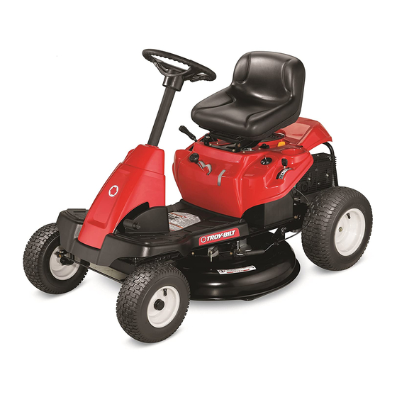
Troy-Bilt 26J Mini-Rider Operator's Manual
Lawn tractor
Hide thumbs
Also See for 26J Mini-Rider:
- Operator's manual (69 pages) ,
- Operation manual (72 pages) ,
- Operator's manual (64 pages)
Table of Contents
Advertisement
Available languages
Available languages
Safe Operation Practices • Set-Up • Operation • Maintenance • Service • Troubleshooting • Warranty
O
'
M
peratOr
s
anual
Lawn Tractor — 26J Mini-Rider
WARNING
READ AND FOLLOW ALL SAFETY RULES AND INSTRUCTIONS IN THIS MANUAL
BEFORE ATTEMPTING TO OPERATE THIS MACHINE.
FAILURE TO COMPLY WITH THESE INSTRUCTIONS MAY RESULT IN PERSONAL INJURY.
TROY-BILT LLC, P.O. BOX 361131 CLEVELAND, OHIO 44136-0019
Printed In USA
Form No. 769-07598A
(January 27, 2012)
Advertisement
Chapters
Table of Contents

Related Manuals for Troy-Bilt 26J Mini-Rider


Summary of Contents for Troy-Bilt 26J Mini-Rider
- Page 1 READ AND FOLLOW ALL SAFETY RULES AND INSTRUCTIONS IN THIS MANUAL BEFORE ATTEMPTING TO OPERATE THIS MACHINE. FAILURE TO COMPLY WITH THESE INSTRUCTIONS MAY RESULT IN PERSONAL INJURY. TROY-BILT LLC, P.O. BOX 361131 CLEVELAND, OHIO 44136-0019 Printed In USA Form No. 769-07598A...
-
Page 2: Table Of Contents
Visit us on the web at www.troybilt.com See How-to Maintenance and Parts Installation Videos at www.troybilt.com/tutorials ◊ Call a Customer Support Representative at (800) 828-5500 or (330) 558-7220 ◊ Write us at Troy-Bilt LLC • P.O. Box 361131 • Cleveland, OH • 44136-0019... -
Page 3: Important Safe Operation Practices
Important Safe Operation Practices WARNING! This symbol points out important safety instructions which, if not followed, could endanger the personal safety and/or property of yourself and others. Read and follow all instructions in this manual before attempting to operate this machine. Failure to comply with these instructions may result in personal injury. - Page 4 Slope Operation A missing or damaged discharge cover can cause blade contact or thrown object injuries. Slopes are a major factor related to loss of control and tip-over Stop the blade(s) when crossing gravel drives, walks, or accidents which can result in severe injury or death. All slopes roads and while not cutting grass.
- Page 5 Children Service Tragic accidents can occur if the operator is not alert to the Safe Handling of Gasoline: presence of children. Children are often attracted to the machine and the mowing activity. They do not understand To avoid personal injury or property damage use extreme the dangers.
-
Page 6: Spark Arrestor
Do not modify engine Periodically check to make sure the blades come to complete stop within approximately (5) five seconds after To avoid serious injury or death, do not modify engine in any operating the blade disengagement control. If the blades way. -
Page 7: Safety Symbols
Safety Symbols This page depicts and describes safety symbols that may appear on this product. Read, understand, and follow all instructions on the machine before attempting to assemble and operate. Symbol Description READ THE OPERATOR’S MANUAL(S) Read, understand, and follow all instructions in the manual(s) before attempting to assemble and operate DANGER—... - Page 8 Symbol Description WARNING—GASOLINE IS FLAMMABLE Allow the engine to cool at least two minutes before refueling. WARNING— CARBON MONOXIDE Never run an engine indoors or in a poorly ventilated area. Engine exhaust contains carbon monoxide, an odorless and deadly gas. DANGER—...
- Page 9 2 — i ection mportant peration racticeS...
-
Page 10: Assembly & Set-Up
Assembly & Set-Up Assembly & Set-Up Contents of Crate • One Riding Mower • One Seat Assembly • One Steering Pedestal Cap • One Steering Wheel/Shaft Assembly • One Rear Engine Cover • One Discharge Chute Assembly • One Rear Hitch Plate •... - Page 11 CAUTION: Tighten the socket head screw and lock nut using provided Do not use any type of power tool (e.g. hex key and a 7/16” wrench or ratchet. impact gun or electric drill with nut driver attached) when tightening the self-tapping bolts to attach the seat bracket.
- Page 12 Install The Rear Engine Cover To adjust the position of the seat, remove the wing knob on the bottom of the seat. Slide the seat forward or backward Install the rear engine cover by positioning it in place as as desired. Reinstall the wing knob. Refer to Fig. 3-5. shown in Figure 3-8.
- Page 13 Connecting the Battery Cables Tire Pressure WARNING! Equal tire pressure should be CALIFORNIA PROPOSITION 65 WARNING maintained at all times. Never exceed the maximum Battery posts, terminals, and related accessories inflation pressure shown on the sidewall of the tire. contain lead and lead compounds, chemicals known to the State of California to cause cancer and The recommended operating tire pressure is: reproductive harm.
-
Page 14: Controls & Features
Controls & Features Clutch/Brake Pedal Speed Control & Parking Brake Lever Fuel Level Indicator Ignition Switch Shift Lever Fuel Fill Cap Throttle/Choke Lever Deck Lift Lever Cup Holder PTO (Blade Engage) Lever Oil Fill Cap Figure 4-1 Lawn Tractor controls and features are illustrated in Fig 4-1 and described on the following pages. WARNING! Read and follow all safety rules and instructions in this manual, including the entire Operation section, before attempting to operate this machine. - Page 15 Throttle / Choke Control The throttle control lever is located on the left fender of the On/Lights tractor seated in the operator’s position, see Fig. 4-1. This lever controls the speed of the engine, as well as the choke when it Start is pushed all the way forward.
- Page 16 Speed Control Lever Deck Lift Lever The speed control lever, located on the right side of the tractor’s Found on your tractor’s right fender, the deck lift lever is used to steering console, allows you to regulate the ground speed of the change the height of the cutting deck.
-
Page 17: Operation
Operation Swivel Seat WARNING Avoid Serious Injury or Death This unit is equipped with a swivel seat feature, which aids the • Know location and function of all controls. operator in mounting and dismounting the unit. • Remove objects which could be thrown by the blades. Note: The seat must be facing forward in the operating position •... -
Page 18: Stopping The Engine
Engage the tractor’s parking brake. Activate the choke control. Turn the ignition key clockwise to the START position. After the engine starts, release the key. It will return to the ON position. IMPORTANT: Do NOT hold the key in the START position for longer than ten seconds at a time. -
Page 19: Engaging The Blades
The lawn tractor is brought to a stop by depressing the Move the throttle control lever to the FAST (rabbit) clutch-brake pedal. position. NOTE: When operating the unit initially, there will be little Grasp the PTO (Blade Engage) lever and pivot it all the way difference between the highest two speeds until after the belts forward into the engaged (ON) position. -
Page 20: Maintenance & Adjustment
Maintenance & Adjustments Maintenance Close the oil drain valve by rotating it clockwise, then reinstall the cap WARNING: Before performing any maintenance or Refill the engine with new motor oil as instructed in the repairs, disengage PTO, move shift lever into neutral Engine Owner’s Manual packed with your unit. - Page 21 • Always keep the rubber boot positioned over the positive terminal to prevent shorting. IMPORTANT: If removing the battery for any reason, disconnect the NEGATIVE (Black) wire from it’s terminal first, followed by the POSITIVE (Red) wire. When re-installing the battery, always connect the POSITIVE (Red) wire its terminal first, followed by the NEGATIVE (Black) wire.
-
Page 22: Seat Adjustment
• Approximately 14 psi for the front tires adjustment. See an authorized Troy-bilt Service Dealer to have IMPORTANT: Refer to the tire sidewall for exact tire your brakes properly adjusted. -
Page 23: Maintenance Schedule
If emptying the fuel system: • Remove the spark plug and pour one (1) ounce of engine oil through the spark plug hole into the • Do not drain fuel when the engine is hot. Allow the cylinder. Crank the engine several times to distribute engine adequate time to cool. -
Page 24: Service
Service Cutting Deck Removal Remove the remaining bow-tie cotter pins securing the deck to the unit, as shown in Fig. 7-3. To remove the cutting deck, proceed as follows: Place the PTO (Blade Engage) lever in the disengaged (OFF) position and engage the parking brake. Lower the deck by moving the deck lift lever into the bottom notch on the right fender. - Page 25 Changing the Deck Belt NOTE: It is possible to change the deck belt with the cutting deck still installed on the tractor, however it is much easier to remove the deck first, change the deck belt, then reinstall the cutting deck. To change the cutting deck belt, proceed as follows: It is easiest to change the deck belt by first removing the cutting deck as instructed earlier in this section first.
-
Page 26: Cutting Blade
Cutting Blade CAUTION: If the jumper battery is installed on a vehicle (i.e. car, truck), do NOT start the vehicle’s WARNING! Shut the engine off and remove engine when jump starting your tractor. ignition key before removing the cutting blade(s) for Start the tractor as instructed in the Operation section of sharpening or replacement. - Page 27 NOTE: Several components must be removed and special tools (i.e. air/impact wrench) in order to change the tractor’s drive belt. See an authorized Troy-bilt Service Dealer to have your drive belt replaced or phone Customer Support as instructed on page 2 for information on ordering a Service Manual.
-
Page 28: Troubleshooting
Troubleshooting Problem Cause Remedy Engine fails to start 1. PTO/Blade engaged 1. Place blade engage lever in disengaged (OFF) position. 2. Spark plug wire disconnected 2. Connect wire to spark plug. 3. Fuel tank empty, or stale fuel 3. Fill tank with clean, fresh (less than 30 days old) gas. -
Page 29: Replacement Parts
Replacement Parts Component Part Number and Description 954-04318 Drive Belt (Mowing Deck) 918-04822A Deck Spindle 942-04385 Cutting Blade (30”) 925-1707D Battery 951-12179A Fuel Tank Cap 951-04366 Fuel Tank Cap (CA) 925-1745A 734-04641 Tire (Rear) 16 x 6.5 x 8 746-04829 Throttle Control/Cable 931-04633 Discharge Chute Assembly... -
Page 30: Attachments & Accessories
Attachments & Accessories The following attachments and accessories are compatible for the Troy-bilt Lawn Tractor. See the retailer from which you purchased your tractor, an authorized Troy-bilt Service Dealer or phone (800) 828-5500 for information regarding price and availability. CAUTION: This Troy-Bilt Lawn Tractor is NOT designed for use with any type of ground-engaging attachments (e.g. - Page 31 Notes...
- Page 32 11— n ection oteS...
-
Page 33: Emissions Statement
FEDERAL and/or CALIFORNIA EMISSION CONTROL WARRANTY STATEMENT YOUR WARRANTY RIGHTS AND OBLIGATIONS MTD Consumer Group Inc, the United States Environmental Protection Agency (EPA), and, for those products certified for sale in the state of California, the California Air Resources Board (CARB) are pleased to explain the emission (evaporative and/or exhaust) control system (ECS) warranty on your outdoor 2006 and later small off-road spark-ignited engine and equipment (outdoor equipment engine) In California, new outdoor equipment engines must be designed, built and equipped to meet the State’s stringent anti-smog standards (in other states, 1997 and later model year equipment must be designed, built, and equipped to meet the U.S. - Page 34 WARRANTED PARTS: The repair or replacement of any warranted part otherwise eligible for warranty coverage may be excluded from such warranty coverage if MTD Consumer Group Inc demonstrates that the outdoor equipment engine has been abused, neglected, or improperly maintained, and that such abuse, neglect, or improper mainte- nance was the direct cause of the need for repair or replacement of the part.
-
Page 35: Warranty
MANUFACTURER’S LIMITED WARRANTY FOR The limited warranty set forth below is given by Troy-Bilt LLC with c. Routine maintenance items such as lubricants, filters, blade respect to new merchandise purchased and used in the United States sharpening, tune-ups, brake adjustments, clutch adjustments,... -
Page 36: Español
Medidas importantes de seguridad • Configuración • Funcionamiento • Mantenimiento • Servicio • Solución de problemas • Garantía anual del peradOr Lawn Tractor — 26J Mini-Rider ADVERTENCIA LEA Y SIGA TODAS LAS INSTRUCCIONES DE ESTE MANUAL ANTES DE PONER EN FUNCIONAMIENTO ESTA MÁQUINA. - Page 37 Visite nuestro sitio web en www.troybilt.com Ver Vídeos demostrativos de instalación de mantenimiento y piezas en www.troybilt.com/Tutorials ◊ Llame al representante de Atención al Cliente al (800) 828-5500 o (330) 558-7220 ◊ Escríbanos a Troy-Bilt LLC • P.O. Box 361131 • Cleveland, OH • 44136-0019...
-
Page 38: Medidas Importantes De Seguridad
Medidas importantes de seguridad ADVERTENCIA: La presencia de este símbolo indica que se trata de instrucciones importantes de seguridad que se deben respetar para evitar poner en peligro su seguridad personal y/o material y la de otras personas. Lea y siga todas las instrucciones de este manual antes de poner en funcionamiento esta máquina. - Page 39 Esté atento a la cortadora y a la dirección de la descarga Los datos estadísticos muestran que los operadores de 60 de los aditamentos y no apunte a nadie. Nunca opere la años y mayores se ven involucrados en un alto porcentaje cortadora de césped sin que estén en su lugar apropiado la de lesiones relacionadas con tractores corta césped.
- Page 40 Servicio No cambie a transmisión neutral para descender. El exceso de velocidad puede hacer que el operador pierda el control de la máquina, ocasionando lesiones graves e incluso la muerte. Manejo seguro de la gasolina: No remolque cargas pesadas detrás de los aditamentos Para evitar lesiones personales o daños materiales sea (carrito de basura cargado, podadora de rodillos, etc) en sumamente cuidadoso al manipular la gasolina.
- Page 41 Antes de limpiar, reparar o inspeccionar la máquina, Según la Comisión de Seguridad de Productos para el compruebe que la(s) cuchilla(s) y todas las partes en Consumidor de los Estados Unidos (CPSC) y la Agencia movimiento se hayan detenido. Desconecte el cable de la de Protección Ambiental de los Estados Unidos (EPA), bujía y póngalo haciendo masa contra el motor para evitar este producto tiene una vida útil media de siete (7) años,...
- Page 42 Símbolos De Seguridad Esta página representa y describe la seguridad los símbolos que pueden parecer en este producto. Lea, comprenda, y siga todas instrucciones de la máquina antes de intentar ensamblar y operar. Symbol Description LEA EL MANUAL(S) DEL OPERADOR leído, entienda, y siga todas las instrucciones en el manual(s) antes de procurar montar y funcionar PELIGRO—...
- Page 43 Symbol Description GASOLINA DE ADVERTENCIA ES INFLAMABLE Permita que el motor se enfríe al menos dos minutos antes del reabastecimiento de combustible. ADVERTENCIA — MONÓXIDO DE CARBONO Nunca dirijas un motor dentro o en un área mal ventilada. Los gases de combustión de motor contienen el monóxido de carbono, un gas inodoro y mortal.
- Page 44 2 — M ection edidaS iMportanteS de Seguridad...
-
Page 45: Montaje Y Configuración
Montaje y Configuración Contenido del cajón • Un Tractor Cortacésped • Un conjunto de asiento • Una tapa de pedestal de dirección • Un conjunto de rueda/eje de dirección • Una tapa trasera del motor • Un conjunto de canal de descarga •... - Page 46 CAUTION: NOTA: Asegúrese de alinear el tornillo de cabeza hueca No use ninguna herramienta eléctrica de manera que la cabeza del tornillo quepa en el orificio (por ejemplo pistola de impacto o taladro eléctrico más grande suministrado en el eje superior de la dirección con el extractor de tuercas colocado) para apretar después de ajustarlo.
- Page 47 Coloque la tapa trasera del motor Coloque la tapa trasera del motor ubicándola en su lugar como se indica en la Figura 3-8. Incline la tapa del motor hacia adelante para que calce dentro de las ranuras provistas, luego rótela hacia atrás para alinear los orificios de montaje.
- Page 48 Conexión de los cables de la batería Presión de los Neumáticos PROPOSICIÓN ADVERTENCIA! 65 de California Advertencia: Los Presión de los neumáticos debe bornes, terminales y accesorios relacionados dar la misma en todo momento. Nunca exceda la contienen plomo y compuestos de plomo, presión máxima de inflado figuran en el flanco del sustancias químicas que el Estado de California que neumático.
-
Page 49: Controles Y Características
Controles y Características Palanca de control de Pedal de freno/embrague velocidad y freno de mano Palanca de cambios Indicador de nivel de combustible De llenado de combustible Cap Módulo del interruptor de encendido Palanca de potencia de arranque (PTO) (enganche de cuchilla) Palanca de estrangulador/obturador Taza de... - Page 50 Acelerador / Control del estrangulador La palanca de control del acelerador está situado en el En/luces guardabarros izquierdo del tractor sentado en la posición del operador, ver fig. 4-1. Esta palanca controla la velocidad del motor, así como el estrangulador cuando se empuja hasta el fondo.
-
Page 51: Freno De Estacionamiento
De Velocidad Palanca de elevación de la plataforma La palanca de control de velocidad, ubicado en el lado izquierdo Ubicada en el guardabarros derecho del tractor, la palanca de del tablero del tractor de la consola, le permite regular la elevación de la plataforma se utiliza para cambiar la altura de velocidad baja del tractor del césped. -
Page 52: Funcionamiento
Funcionamiento Colocación del freno de mano ADVERTENCIA Para colocar el freno de mano: Presione totalmente el pedal del embrague-freno y PARA EVITAR LESIONES manténgalo hacia abajo con el pie. PERSONALES GRAVES O LA MUERTE Mueva la palanca de control de velocidad totalmente hacia abajo en la posición de freno de mano. - Page 53 Detención del motor Coloque la palanca de cambios en neutral, Coloque el freno de estacionamiento, ¡ADVERTENCIA! Si golpea contra algún objeto Apague el motor y retire la llave. Eso permitirá reducir al extraño, detenga el motor, desconecte el(los) mínimo la posibilidad de que su césped resulte quemado cable(s) de la bujía y conecte el motor a masa.
- Page 54 Faros delanteros NOTA: Modelos con modo de precaución en marcha atrás: El motor se apagará automáticamente si la potencia de arranque (PTO) está enganchada con la palanca de cambios en posición de • Los faros están encendidos cuando el motor del tractor se marcha atrás con la llave de encendido en la posición de CORTE está...
-
Page 55: Mantenimiento Y Ajustes
Mantenimiento y Ajustes Mantenimiento Gire la válvula de drenaje hacia la izquierda para abrir la válvula y comenzar el flujo de petróleo. De drenaje de ¡ADVERTENCIA! Antes de realizar cualquier tipo de aceite en un recipiente adecuado con una capacidad de no mantenimiento o servicio, desenganche todos los menos de 64 oz controles y detenga el motor. - Page 56 Dirección de piñón y cremallera Batería Una vez por temporada, o cada 25 horas de funcionamiento, será La batería está sellada y no necesita mantenimiento. Los niveles necesario para la lubricación de la cremallera y piñón situado en de ácido no se pueden controlar. la parte delantera de la unidad.
-
Page 57: Ajuste Del Freno De Estacionamiento
No inflar demasiado. La presión desigual del neumático necesidad de ajuste. Ver una autorización Troy-Bilt distribuidor de puede causar la plataforma de corte para cortar de forma desigual. -
Page 58: Programa De Mantenimiento
• Añadir a la gasolina limpia y fresca la cantidad • Desconecte la manguera de combustible y drenar el correcta de estabilizador de la capacidad del sistema resto de la gasolina en el sistema. de combustible. ¡ADVERTENCIA! La gasolina es una sustancia tóxica. -
Page 59: Servicio
Servicio Eliminación de la cubierta de corte Retire el resto de la pajarita-chavetas asegurar la cubierta a la unidad, como se muestra en la Fig. 7-3. Para eliminar la plataforma de corte, haga lo siguiente: Coloque la PTO (enganche de cuchilla) en la palanca de desconexión (OFF) y el freno de estacionamiento. - Page 60 Cambio de la correa cubierta Alimentar el cinturón de la cubierta a través del soporte guardacorrea y trabajar a su alrededor y en la polea de NOTA: Es posible cambiar la correa de la cubierta con la transmisión de la TDF, como se muestra en la Fig. 7-2. plataforma de corte sigue instalado en el tractor, sin embargo, es mucho más fácil quitar la cubierta en primer lugar, cambiar la correa de la cubierta, vuelva a instalar la plataforma de corte.
- Page 61 Corte de la hoja Conecte el segundo cable negativo (-) para el otro puesto de la batería del puente. ¡ADVERTENCIA! Apague el motor y retire la llave Hacer la conexión final en el bloque del motor del tractor, de encendido antes de retirar la cuchilla de corte (s) lejos de la batería.
- Page 62 NOTA: Varios componentes deben ser retirados y herramientas especiales (es decir, aire / llave de impacto) con el fin de cambiar la correa del tractor unidad. Ver autorizado Troy-Bilt distribuidor de servicio para que su correa de transmisión reemplazado o soporte telefónico al cliente como se indica en la página 2 para obtener información sobre cómo pedir el manual de...
-
Page 63: Solución De Problemas
Troubleshooting Problem Cause Remedy Motor no arranca 1. Perilla de potencia de arranque (PTO) 1. Coloque la perilla en la posición de conectada. desconexión (OFF). 2. No está colocado el freno de mano. 2. Coloque el freno de mano. 3. Se ha desconectado el cable de las bujías. 3. -
Page 64: Piezas De Reemplazo
Piezas de reemplazo Componente Número de Parte y Descripción 954-04318 Cinturón de Paseo 918-04822A Huso de Cubierta 942-04385 Lámina (30”) 925-1707D Batería 951-12179A Gorra de Depósito de combustible 951-04366 Gorra de Depósito de combustible (CA) 925-1745A Llave 734-04641 Neumático (delanteros) 16 x 6.5 x 8 746-04829 Control/Cable de Regulador 931-04633... -
Page 65: Aditamentos Y Accesorios
Aditamentos y accesorios Los siguientes aditamentos y accesorios son compatibles con los Tractores Corta Césped Modelo. Consulte al minorista a quien le adquirió su tractor, a un distribuidor autorizado MTD de mantenimiento o llame al teléfono (800) 800-7310 para obtener información sobre precios y disponibilidad. - Page 66 DECLARACIÓN FEDERAL y/o DE CALIFORNIA SOBRE GARANTÍAS EN EL CONTROL DE EMISIONES SUS DERECHOS Y OBLIGACIONES EN CUANTO A LA GARANTÍA MTD Consumer Group Inc, la Agencia de Protección Medioambiental de los Estados Unidos (EPA), y para aquellos productos certificados para su venta en el es- tado de California, el Departamento de los Recursos del Aire de California (CARB) se complacen en explicar la garantía que cubre al sistema de control (ECS) de emisiones (evaporativas y/o de escape) de su equipo y motor (motor de equipos de exteriores) de encendido por chispa para todo terreno, pequeño, de exteriores del año 2006 y años posteriores En California, los nuevos motores de equipos de exteriores deben estar diseñados, construidos y equipados para cumplir con las...
- Page 67 8. Durante la totalidad del período de garantía del motor y equipo para todo terreno arriba mencionado, MTD Consumer Group Inc mantendrá un suministro de piezas bajo garantía suficiente para satisfacer la demanda esperada de tales piezas. 9. Cualquier pieza de reemplazo se podrá usar para el cumplimiento del mantenimiento o las reparaciones bajo garantía y se suministrarán sin cargo para el propietario.
-
Page 68: Garantía
Las disposiciones de esta garantía cubren el recurso de reparación zapatas antideslizantes, ruedas de fricción, placas de raspado, gomas única y exclusiva que surge de la venta. Troy-Bilt no se hará helicoidales y neumáticos. responsable de ninguna pérdida o daño incidental o resultante, incluyendo sin limitación, los gastos incurridos para los servicios...
Need help?
Do you have a question about the 26J Mini-Rider and is the answer not in the manual?
Questions and answers
belt keeper rod and belt picture
The belt keeper rod holds the deck belt in place and guides it around the pulleys. The belt is a looped rubber component that fits around the PTO drive pulley and through the belt keeper rod. To remove it, you roll one side off the pulley and pull it forward through the keeper rod.
This answer is automatically generated
Where is the fuel filter located on a troy Bilt model TB 110? Is there even one on this model?