Advertisement
Quick Links
IMPORTANT - The channel needs to be
INSTALLATION
slightly over-filled to ensure a good contact.
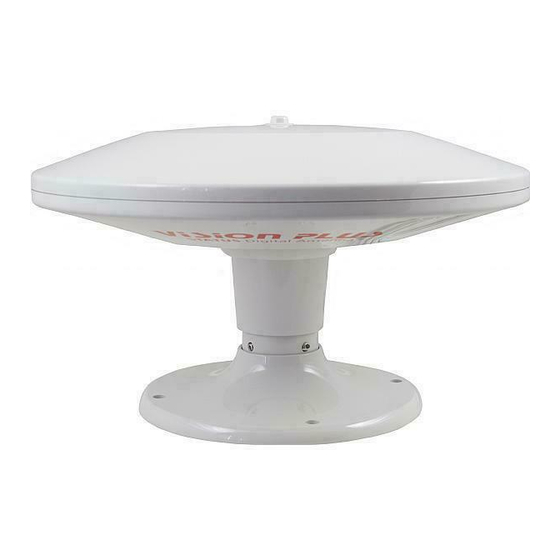
The Antenna Dome
3. Place in position centrally over the
drilled hole and secure with the four
16mm self tapping screws.
4. Once the sealant has set, thread the
coaxial cable through the roof, pulling
through the cable as the antenna is
lowered, making sure the cable does
not snag, kink, chafe or become
trapped.
5. Push the Antenna Dome into position,
ensuring it is properly seated in the
Mounting Foot. Secure by tightening
the two grub screws with the Allen
Key.
Angle Adjustment.
Positioning
When positioning the Antenna Dome
please allow for the following:-
1. Place above a wardrobe or locker to
provide a suitable location for the
Power Amplifier below.
2. Position as high as possible to ensure
Only relevant if you are mounting Status
Status is not shielded from incoming
on a sloping surface. Level fixing is very
signals.
important to ensure optimum performance.
3. Do not place within one metre of
1. To adjust the angle, remove the Antenna
any metal protrusions such as roof
Dome from the Mounting Foot and
racks, metal flues, metal poles etc. as
turn the Antenna Dome upside down.
this may cause picture distortion.
2. With a screwdriver loosen the Central
4. On a Caravan or Motorhome mounting
Bolt, adjust the Adapter to the desired
on the offside will reduce collision
angle and re-tighten the central bolt.
with overhead obstructions.
3. Push the Antenna Dome into position,
Fixing
ensuring it is properly seated in the
Mounting Foot. Secure by tightening
1. Make a hole 15mm in diameter, large
the two grub screws with the Allen
enough for the coaxial cable with plug
Key.
fitted to be passed through, making
sure there are no sharp edges that
The Power Amplifier
could cut or chafe the cable.
2. Remove the Mounting Foot from the
Positioning & Fixing
Antenna Dome. Turn the Mounting
1. Locate the Power Amplifier in the
Foot upside down and with a SEALANT
wardrobe or locker below the Antenna
ADHESIVE fill the channel around the
Dome where it is easily accessible and
edge, including around the holes for
where possible close to the TV position.
the fixing screws.
2. Fix in place using the two 38mm
Pole Fitting
screws
Wiring to Power Supply
1. Status requires a 12-24 volt power
supply from a fused auxiliary outlet fed
from the battery. If wiring direct to a battery
we recommend an in-line fuse (max 5
amp) on the positive wire. If unsure
please consult with a qualified installer.
RED STRIPE +VE, BLACK –VE
DO NOT connect into any other 12 volt
power cables as they may carry electrical
interference which will cause picture
distortion.
Connecting the Antenna
1. Remove the Mounting Foot from the
1. Shorten the cable from the Antenna
Antenna Dome.
Dome to the required length to reach
the Power Amplifier - DO NOT COIL ANY
2. The Adapter is now ready to
EXCESS CABLE.
accommodate any 25mm pole, such
as those in the Vision Plus Range.
2. Trim the cable and refit the F-Connector
as described in this guide.
3. The coaxial cable can be threaded
down the centre or outside of the
3. Once fitted, connect the Antenna to the
pole.
'ANT.IN' socket.
4. If the cable is being fed down the
DO NOT secure the cable with any staples or 'P'
outside please ensure that the top of
Clips as this may damage the cable, it is best
the pole does not rub or cut the
left loose.
coaxial cable when being pushed into
place.
Connecting to your Television
5. Once the pole is in place, secure by
To connect to your television you will need
tightening the two grub screws with
to run a cable to your TV position to the Power
the Allen key.
Amplifier. There are many options available
IMPORTANT – Status is not designed to be
dependant on your particular installation.
You may well require additional cable,
used in conjunction with a 'through-the-
connectors, plugs or sockets which are
roof' pole kit.
available from ourselves or through your
local dealer.
Removing the Antenna
Whenever routing the cable or fitting
connectors please follow our Important
A permanently fitted Status may be
Guideline below.
removed if there are severe height
restrictions, leaving only the Mounting Foot
Operating the System
in place.
1. Switch ON the Power Amplifier and the
1. Disconnect the Antenna from the Power
blue LED will illuminate.
Amplifier. On the Adapter loosen the
2. Check the gain control switch is set to
two grub screws with the Allen key
and lift off whilst carefully feeding out
maximum by rotating clockwise.
the coaxial cable with plug attached.
3. Turn on your television set and tune in.
This may be necessary at all new
2. Push the Blanking Cap supplied into
locations
place to cover the central hole.
.
Removing the Pinnacle
This may be necessary should you wish to
reduce the overall height of the antenna by
90 mm.
1. Simply unscrew the Pinnacle and
remove. The antenna is designed to
remain water tight without the
Pinnacle.
2. To replace, simply screw in and tighten
BY HAND.
3. IMPORTANT - The Pinnacle is an
integral part of the antenna and
critical to its performance. When in
use always ensure the Pinnacle is fitted.
Grade UK Limited
8 FinchClose
Lenton Lane
Nottingham NG7 2NN
Tel: 0115 986 7151
email: info@gradeuk.co.uk
www.gradeuk.co.uk
Advertisement

Summary of Contents for Vision Plus STATUS 330
- Page 1 Power Amplifier - DO NOT COIL ANY 2. The Adapter is now ready to EXCESS CABLE. accommodate any 25mm pole, such as those in the Vision Plus Range. 2. Trim the cable and refit the F-Connector Positioning as described in this guide.
- Page 2 TV to confirm that the amplifier is coaxial plugs and couplers which are operational. available from our Vision Plus Range through The pinnacle is essential for the optimum our dealers or directly from ourselves. Minor pixilation, will not receive all...
Need help?
Do you have a question about the STATUS 330 and is the answer not in the manual?
Questions and answers