
Subscribe to Our Youtube Channel
Related Manuals for vanEE 90 H

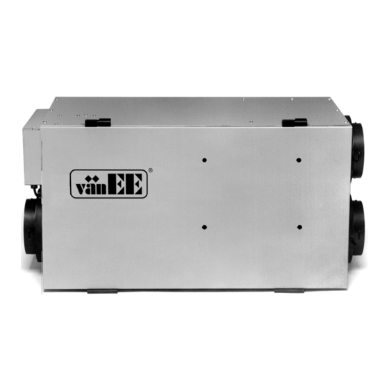
Summary of Contents for vanEE 90 H
-
Page 1: Installation Manual
Installation Manual ® Ventilation Systems VB0023 B R O N Z E M O D E L S 90 H 190 H 03451 19/10/01... -
Page 2: Table Of Contents
TABLE OF CONTENTS ........3 ECHNICAL Air Distribution (Normal Operation) ......3 Air Distribution (Defrost) . -
Page 3: Technical Data
1.0 TECHNICAL DATA 1.1 Air Distribution (Normal Operation) STALE AIR FRESH AIR TO OUTSIDE TO BUILDING STALE AIR FRESH AIR FROM BUILDING FROM OUTSIDE VF0022 1.2 Air Distribution (Defrost) FILTERED AIR TO BUILDING STALE AIR FROM BUILDING VF0023 Outside Temperature Defrost Cycles Extended Defrost Cycles* Defrosting (min.) Operation time (min.) Defrosting (min.) Operation time (min.) -
Page 4: Typical Installations
2.0 TYPICAL INSTALLATIONS There are three (3) common installation methods. 2.1 Fully Ducted System (Primarily for homes with radiant hot water or electric baseboard heating. See figure 1.) Moist, stale air is exhausted from the high humidity areas in the home, such as bathrooms, kitchens and laundry rooms. -
Page 5: Installation
3.0 INSTALLATION NSPECT THE ONTENTS OF THE • Inspect the exterior of the unit for shipping damage. Ensure that there is no damage to the door, door latches, door hinges, dampers, duct collars, cabinet, etc. • Inspect the interior of the unit for damage. Ensure that the fan motor assembly, heat recovery core, insulation, dampers, damper actuator, and drain pan are all intact. -
Page 6: Calculating Duct Size
3.0 INSTALLATION (CONT’D) 3.3 Calculating Duct Size Use the table below to ensure that the ducts you intend to install will be carrying air flows at or under the recommended values. Avoid installing ducts that will have to carry air flows near the maximum values and never install a duct if its air flow exceeds the maximum value. -
Page 7: Installing Ductwork And Registers
3.0 INSTALLATION (CONT’D) 3.4 Installing Ductwork and Registers WARNING Never install a stale air exhaust register in a room where a combustion device is, such as a gas furnace, a gas water heater or a fireplace. 3.4.1 Fully ducted system (as illustrated in Section 2.1) Stale air exhaust ductwork: •... - Page 8 3.0 INSTALLATION (CONT’D) Method 2: return side connection • Cut an opening into the furnace return duct at a minimum distance of 10 linear feet upstream where the furnace return duct connects to the furnace cabinet, as measured VD0108 figure 10 minimum along the lenght of the duct.
-
Page 9: Connecting Duct To The Unit
3.0 INSTALLATION (CONT’D) 3.5 Connecting Duct to the Unit Insulated flexible duct: Use the following procedure for connecting the insulated flexible duct to the ports on the unit (exhaust to outside and fresh air from outside). a) Pull back the insulation to expose the flexible duct. b) Connect the interior flexible duct to the opening using a duct tie. -
Page 10: Connecting The Drain
3.0 INSTALLATION (CONT’D) Make sure the intake hood is at least 6 feet (1.8 m) away from any of the following: • dryer exhaust, high efficiency furnace vent, central vacuum vent • gas meter exhaust, gas barbecue-grill • any exhaust from a combustion source •... -
Page 11: Installation Of The Controls
4.0 INSTALLATION OF THE CONTROLS 4.1 Electrical Connection to BRONZE Control GREEN BLACK wire wire NOTE: Disregard other terminals (they are not used). R G B F F I OC OL Y VE0051 4.2 Electrical Connection to Optional Controls MAIN PC BOARD PUSH-BUTTON SWITCHES CRANK TIMER (Optional) -
Page 12: Balancing
5.0 AIR FLOW BALANCING HAT YOU EED TO ALANCE THE • A magnehelic gauge capable of measuring 0 to 0.5 inches in water (0 to 125 Pa) and 2 plastic tubes. • The balancing chart of the unit. RELIMINARY TAGES TO ALANCING THE VP0009 •... -
Page 13: Overall Verification
6.0 OVERALL VERIFICATION 6.1 3-Position Switch This procedure allows the installer to verify that all modes of operation are fully functional. During the verification of the 3-position switch, make sure that all optional remote controls are inactive. Results expected Set switch to fan speed / damper low speed / open HIGH... -
Page 14: Maintenance
7.0 MAINTENANCE WARNING Risk of electrical shocks. Before performing any maintenance or servicing, always disconnect the unit from its power source. • Review with the user the steps required for regular maintenance of his/her ventilation system. These steps are described in detail in the user manual: FOUR TIMES A YEAR: •... -
Page 15: Troubleshooting
9.0 TROUBLESHOOTING Note: Be sure to unplug and inspect the unit before proceeding with these steps. Start with point 1,then point 2 and so on. Start-up troubleshooting: Problems Possible causes You should try this 1. Unit doesn't work. • Erratic operation of the electronic circuit. • Unplug the unit. Wait for 30 seconds. Plug it back in. •... - Page 16 9.0 TROUBLESHOOTING Problems Possible causes You should try this 5. The defrost cycle • Ice deposits may be hindering • Remove the ice. doesn't work the damper operation. (the fresh air duct is • The damper rod or the port •...
Need help?
Do you have a question about the 90 H and is the answer not in the manual?
Questions and answers