
Related Manuals for bmb-home HOME PROTECTOR+

Summary of Contents for bmb-home HOME PROTECTOR+
- Page 1 WIRELESS SECURITY SYSTEM HOME PROTECTOR+ USERS’ MANUAL PROTECTOR+ SYSTEM AND BASE CONSOLE INSTRUCTIONS...
- Page 2 NOTES: P/N 033000=13610 Rev. 01-02-06 BMB Home Security...
- Page 3 INDEX Introduction Safety warnings 1. HOME PROTECTOR+ Surveillance System 1.1 Important properties 1.2 Signal range 2. Security Console SC28 2.1 Installing the SC28 Console and attaching the cables 2.1.1 Connecting the telephone wire 2.1.2 Connecting the AC adapter 2.1.3 Emergency / Back-up batteries 2.2 Locating the Security System Components 2.3 The Base Console menus 2.3.1 Choosing a language...
- Page 4 8. Advanced System Functions 8.1 Setting Delays 8.2 Clearing the memory of the Security Base Console 8.3 Changing the access code (PIN) 9. Advanced Security Functions 9.1 Disarming the siren for silent alarm 9.2 Using the Chime function 9.3 Using wired inputs of the Base Console 9.4 Adding a wired sensor to the Door/Window Sensor DS18 9.5 Emergency sensors 9.6 Sensor 27-32 ON/OFF...
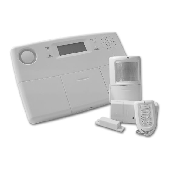
- Page 5 1. The surveillance system The contents of the Home Security Protector+ system: This kit is an effective security system for your home. In this kit you can find the following components: 1. Security Base Console SC28 2. Motion Detector MS18 3.
- Page 6 1.2 Signal Range The sensors have an open air range of up to 100m, but less in a built environment. Walls, ceilings and other large object will influence the range. The range depends strongly on the property’s environmental conditions. One other factor that can decrease the range is the presence of other (distorting) high-frequency signals on the same RF frequency (433MHz).
- Page 7 LCD Display 1. Zone numbers Every sensor represents a so-called zone in the system. There are 30 zones for wireless sensors (numbers 1-30 on the display) and 2 zones for wired sensors (numbers 31 and 32 on the display). Zone numbers on: Door or window is open. Zone number flashing slowly: There is a problem with the sensor (6.5).
- Page 8 Mounting the console onto the wall The console can be mounted onto the wall using two screws. On the back of the console you will find two slot holes (heart to heart distance 96mm). Fitting screws are included with the set. Place the console on a flat surface If you choose not to mount the console, you can attach the rubber feet-caps (included) to the back of the console.
- Page 9 5. NEW PIN Change your PIN code (8.3). 6. MEMORY CLEAR Clear all sensors, remote controls, thermostats, timers or settings (8.2). Sub-menu: CLEAR ALL SENSORS Remove a registered sensor. CLEAR ALL REMOTES Remove a registered remote control. CLEAR ALL TIMERS Remove all timer settings at once. CLEAR ALL THERMOSTATS Remove all timer settings at once.
- Page 10 3. Installing remote controls 3.1 Key Chain Remote Control KR18 1. Control indicator Comes on when the remote control sends a radio signal when keys are pressed. When the indicator blinks only weakly, the batteries have to be replaced. 2. Arm Switches on the Security System in the Arm Away Mode.
- Page 11 3.2 Comfort Remote Control SH600 1. Panic When this key is pressed, an immediate alarm will be initiated by the Security System 2. Control Indicator Comes on when the remote control sends a radio signal when keys are pressed. When the indicator blinks only weakly, the batteries have to be replaced.
- Page 12 If you have more than 2 remote controls installed, it will show e.g. RMOT 3 SET, RMOT 4 SET, … RMOT 16 SET. You can register up to 16 remote controls. 6. Repeat step 5 for every remote control you wish to register. 7.
- Page 13 4.1.2 Using the Door/Window Sensor 1. Open the casing by taking the two parts apart.. 2. Insert batteries (2xAAA, alkaline) into the battery compartment. Observe polarity. 3. Set the switch for entry delay (5) to MIN when you have installed the sensor on a window and on MAX when the sensor is installed on a door.
- Page 14 4.2 Motion Detector MS18 1. Control Indicator - Lights up when a signal is transmitted. 2. PIR 3. Tamper contact. 4. Battery compartment. 5. Sensitivity switch 1/2 - In setting 1 the sensor will instantly react to movement, in setting 2 the sensor is less sensitive and will only react after registering multiple movements.
- Page 15 If required you can remove Additional (Wireless) Sensors from the memory. This method is described in 8.2. All information on mounting the respective detector can be found in the user manual of the respective detector. 4.4 Thermostat TS10 DigiMax210 (*OPTIONAL) www.bmb-home.com The DigiMax210 is available separately. Please visit for more information.
- Page 16 5. Setting up the Security Console (SC28) 5.1 Setting the clock 1. To access the menu, press either the menu UP ? o r DOWN ? b utton. The display now shows ENTER PIN. 2. Enter your 4-digit PIN code (factory setting 0000. See 8.3 for changing the PIN code). The display is cleared and shows a * for each number entered.
- Page 17 4. Use the menu buttons UP/DOWN? to go to menu item 4. MESSAGE. Press OK to select this menu item. You can also go to this menu item directly by pressing a 4 on the number pad. 5. Press 1 for RECORD. 6.
- Page 18 6.2 Panic alarm The panic alarm can be switched on in case of an emergency, independent of whether the security system is Armed or Disarmed. The telephone message indicates the emergency sensor is triggered and that it is not the burglar alarm. This is done by a default extra message to your own spoken telephone message.
- Page 19 Device/Switch Module. Plug-in module to switch lighting and electrical equipment. LM15 Bayonet Lamp Module or Screw-In Lamp Module to switch lighting. www.bmb-home.com More information on these modules can be found on or you can contact your local dealer. 7.2 Addressing your modules An address can be set for every X10 module.
- Page 20 7.7 Comfort functions of the security console You can also control the modules using the console. If you do not see a menu item, the console is in HOME CONTROL mode. The display shows HOME CONTROL. To control a module with Unit Code 1, press “1” followed by “ON” or “OFF”.
- Page 21 7.9 Clearing the timer settings 1. To access the menu, press the menu UP or menu DOWN ? b utton. The display now shows ENTER PIN. 2. Enter your 4-digit PIN code (factory setting 0000. See 8.3 for changing the PIN code). The display is cleared and shows a * for each number entered.
- Page 22 1. To access the menu, press the menu UP? or menu DOWN? button. The display now shows ENTER PIN. 2. Enter your 4-digit PIN code (factory setting 0000). For every digit entered, a * will appear. 3. When the PIN code has been entered correctly, the word INSTALL will show up on the display. 4.
- Page 23 9.4 Adding a wired sensor to the Door/Window Sensor DS18 The DS18 Door/Window Sensor has an input or contact for an extra wired sensor. These sensors need to be of type NC (normally closed contacts). There should not be any power on this contact (potential-free). A few examples: •...
- Page 24 Plug & Play modules a large number of built-in switches, in-wall and sun blind switches, remote controls and special modules are available. With the addition of these modules you can control nearly everything that is www.bmb-home.com electrically powered in your home via your security system Base Console. See (Product group Home Automation) for more information.
- Page 25 Universal Siren Connect an own siren to a AM12 or B6 (=HC+1, UC=6) AD10 module. H.A. Automation H.A. functions in respond to sensor (27-32) B7 – B12 when in ARMED mode and triggered. (=HC+1, UC=7-12). Thermostats Thermostat H.A. addresses. B13 – B16 (=HC+1, UC=13-16).
- Page 26 Temperature levels and settings in a glance: LEVEL USED BY Ambient temperature Measured by individual thermostat always Thermostat Comfort level Set individually per thermostat normal mode Console Comfort level Set in console, per thermostat T1–T4 timed events only Console Economy level Set in console, applies for all Thermostats armed / timed / phone Console Frost level...
- Page 27 11.3 Operating the alarm functions via an outside phone 1. Call your home number. The console will answer. 2. You will hear ‘Please enter PIN’. Enter your 4-digit PIN code. 3. If your PIN is correct, you will hear ‘PIN accepted’. If your PIN is incorrect, you will hear ‘Error’. 4.
- Page 28 Key Chain Remote Control KR18 – 2x CR2016 batteries • A new KR18 contains fully charged batteries. If the indicator light on the KR18 is not very bright, the batteries should be replaced. • Open the remote control (back). Use CR2016, 3V lithium batteries (2x). •...
- Page 29 13. Frequently asked questions Why does the security system not work? Check whether you see any text on the console display. If not: check whether the AC adapter is connected to the mains, whether the electrical wire is plugged into the adapter and whether the plug is connected to the console.
- Page 30 P/N 033000=13610 Rev. 01-02-06 BMB Home Security...
-
Page 31: Sensor Type
TABLE SENSORS ZONE LOCATION: SENSOR TYPE: Note: entrance delay on motion sensor Note: entrance delay on motion sensor WIRED INPUT 1 WIRED INPUT 2 TABLE TELEPHONE NUMBERS MEMORY TELEPHONE NUMBER NAME CONTACT PERSON: P/N 033000=13610 Rev. 01-02-06 BMB Home Security... -
Page 32: Declaration Of Conformity
DECLARATION OF CONFORMITY BMB HOME herewith declares that the device “Protector+” complies with the essential requirements and other applicable provisions of the R&TTE 1999/5/EC directive. Product category: general consumer (category 3). WWW.BMB-HOME.COM X10 EUROPE François Rossi Peter Schoon P/N 033000=13610 Rev. 01-02-06...
Need help?
Do you have a question about the HOME PROTECTOR+ and is the answer not in the manual?
Questions and answers