Table of Contents
Advertisement
NOTE: Read the entire instruction manual before starting the
installation.
SAFETY CONSIDERATIONS
Improper installation, adjustment, alteration, service, maintenance,
or use can cause explosion, fire, electrical shock, or other
conditions which may cause personal injury or property damage.
Consult a qualified installer, service agency, or your distributor or
branch for information or assistance. The qualified installer or
agency must use factory authorized kits or accessories when
modifying this product. Refer to the individual instructions pack-
aged with the kits or accessories when installing.
Follow all safety codes. Wear safety glasses and work gloves.
Read these instructions thoroughly and follow all warning or
cautions attached to the unit. Consult local building codes and
National Electric Code (NEC) for special requirements.
Recognize safety information. This is the safety-alert symbol
When you see this symbol on unit or in instructions and manuals,
be alert to potential for personal injury.
Understand the signal word DANGER, WARNING, or CAU-
TION. These words are used with the safety-alert symbol. DAN-
GER identifies the most serious hazards which will result in severe
personal injury or death. WARNING signifies a hazard which
could result in personal injury or death. CAUTION is used to
identify unsafe practices which would result in minor personal
injury or product and property damage. NOTE is used to highlight
suggestions that will result in enhanced installation, reliability, or
operation.
INTRODUCTION
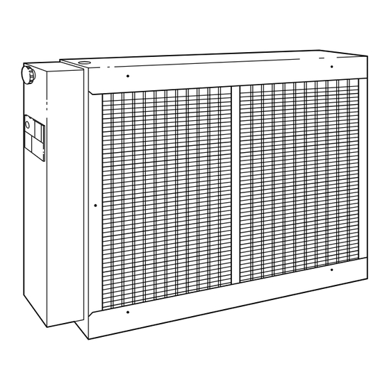
Model 9011KAX Electronic Air Cleaner (EAC) is available in 3
sizes: 012 (300 to 1400 CFM), 016 (500 to 1800 CFM), and 020
(700 to 2000 CFM). (See Fig. 1.)
These plate-type air cleaners are designed for use with residential
and light commercial forced-air heating and/or cooling systems.
They may be installed in the vertical or horizontal section of a
typical return-air duct system. (See Fig. 2.)
These air cleaners are easily field-converted from right- to left-
hand units. Cabinets are designed to support up to 400 pounds
when used in under-the-furnace applications.
A. Cabinet
The cabinet includes an electrical junction box and power safety
interlock, and houses the air cleaner components. These compo-
nents are:
1. Mechanical pre-filters—Expanded aluminum mesh first-
stage filter that removes lint and large dust particles.
2. Cell assemblies—Cells consisting of combined ionizer
wires and collector plates.
Ionizer part of cell has tungsten wires that receive positive
charge and are mounted between grounded aluminum
channels supported by glazed ceramic insulators.
Collector part of cell consists of alternately charged collec-
tor plates.
Installation, Start-up
and Service Instruction
ELECTRONIC AIR CLEANER
.
—1—
Cancels: II 901K-12-3
Fig. 1—Model 31KAX
The EAC components are listed below and shown in Fig. 3.
1. Power door assembly.
2. Two pre-filters.
3. Cabinet containing 2 air-cleaning cell assemblies.
4. A parts bag including electrical bushing, plug buttons, wire
chase, and airflow label.
B. Power Door Assembly
The power door assembly consists of:
1. Unit operation light, ON-OFF switch, and door attachment
knob—all installed on door cover.
2. Door base plate contains a solid-state power pack that
converts 120vac to high voltage DC (a 240v Conversion
Kit, KEAVC0101240 is available). All wiring is mounted
internally. A line-voltage disconnect (male plug) and high-
voltage buss bar are mounted on the base plate externally.
Four screws must be removed to expose the power pack and
wiring.
The supply circuit to the power pack, which is wired across the
furnace blower motor, is controlled by an ON-OFF power switch.
With the power switch ON (assuming power door is in place and
blower motor is operating), 120vac ± 10 percent single-phase, 60
Hz power is applied to the power pack (240v conversion kit
transformer converts 240v to 120vac). Output of the power pack
assembly is approximately 7300vdc.
These Installation Instructions consist of the following:
Section I—Locating Unit
Section II—Installation
Section III-Electrical Connections
Section IV-Startup and Adjustments
Section V—Routine Maintenance and Service
901KAX
II 901K-12-4
10-01-94
A91465
Advertisement
Table of Contents

Subscribe to Our Youtube Channel
Related Manuals for Bryant 901KAX


Summary of Contents for Bryant 901KAX
- Page 1 Installation, Start-up 901KAX and Service Instruction ELECTRONIC AIR CLEANER Cancels: II 901K-12-3 II 901K-12-4 10-01-94 NOTE: Read the entire instruction manual before starting the installation. SAFETY CONSIDERATIONS Improper installation, adjustment, alteration, service, maintenance, or use can cause explosion, fire, electrical shock, or other conditions which may cause personal injury or property damage.
-
Page 2: Locating Unit
⁄ -IN. ELECTRICAL ENTRANCE FOR DUCT APPLICATION ″ ⁄ REAR MOUNTING FLANGE OPERATION LIGHT 3″ KNOB ″ ⁄ ″ ⁄ 21″ LOGO 1″ ON/OFF SWITCH ELECTRICAL ENTRANCE ( ⁄ -IN. DIA) REMOVABLE FOR FURNACE APPLICATIONS POWER DOOR A91466 MODEL 901KAX012 24-3/4 21-3/4 19-1/2... -
Page 3: Installation
PRE-FILTERS CELL ASSEMBLY POWER DOOR ASSEMBLY A91467 Fig. 3—View of Major Components NOTE: The maximum operating temperature of the EAC is CAUTION: Cabinets will support a maximum weight of 125°F. 400 lbs when installed beneath a vertical furnace or air-handling unit. When setting furnace on cabinet, do not II. -
Page 4: Electrical Connections
SUPPLY AIR PLENUM COOLING AIRFLOW COIL COOLING COIL UPFLOW FURNACE 3 TO 1 TRANSITION DUCT WORK ELECTRONIC AIR CLEANER ALTERNATE AIR CLEANER POSITION RETURN AIR PLATFORM GAS SUPPLY UPFLOW APPLICATION A91468 ELECTRONIC AIR CLEANER UPFLOW FURNACE FURNACE SIDE APPLICATION A91469 RETURN AIR PLENUM ELECTRONIC... - Page 5 FURNACE FURNACE FURNACE KNOCKOUTS KNOCKOUTS KNOCKOUTS ⁄ ⁄ ⁄ DIA HOLE DIA HOLE DIA HOLE ″ ″ ″ ⁄ ⁄ ⁄ ″ ″ ″ ⁄ ⁄ ⁄ ″ ″ ⁄ ⁄ ″ ⁄ ″ ⁄ REAR OF ⁄ REAR OF REAR OF FURNACE DIA HOLE...
- Page 6 NOTE: For non-corporate furnaces, wire unit using conduit and CAUTION: Be sure all internal wiring connections are strain relief the wires. tight before power is returned to the unit. B. External Electrical Connections IONIZER 1. Attach power supply conduit to hole in top of EAC. Do not WIRES use extension cord to connect to electrical power source.
-
Page 7: Startup And Adjustments
POWER SUPPLY (120V-60HZ-10) FAN SWITCH POWER SUPPLY (120V-60HZ-10) FAN RELAY FAN SWITCH FAN MOTOR FAN MOTOR TO "G" ON WHT OR YEL THERMOSTAT ELECTRONIC AIR CLEANER AIR CLEANER RELAY (FIELD TO "C" ON SUPPLIED) WIRENUT, FACTORY SUPPLIED THERMOSTAT 120-V FIELD WIRING ELECTRONIC WIRENUT, FACTORY SUPPLIED AIR CLEANER... -
Page 8: Routine Maintenance And Service
FK4B 110 VAC BRANCH CKT AUX1 AUX2 GND HOT NEUT EAC1 EAC2 EAC1 EAC2 240:120-V PLUG 30 VA TRANSFORMER TO 240-V ELECTRONIC AIR CLEANER (WITH 240-V CONVERSION TO 120-V KIT INSTALLED) ELECTRONIC 24 VDC RELAY AIR CLEANER SCREW TERMINAL WIRENUT, FACTORY SUPPLIED 120-V FIELD WIRING A91489 A93217... - Page 9 115-VAC 115-VAC NEUTRAL LINE CIRCUIT 115-VAC TERMINALS VOLTAGE TRANSFORMER BREAKER PL-1 PR-2 PR-1 9-PIN HEATING CONNECTOR SPEED TAP TERMINAL EAC-1 24-VAC COMMON COOLING SEC-2 EAC-2 SPEED TAP TERMINAL 24-VAC POWER SEC-1 MAX. 1.0 AMPS 115-VAC 24-VAC FUSE 3-AMP UNCUT: 120 SEC FUSE 3-AMP ONLY CUT: 180 SEC...
- Page 10 EAC - ELECTRONIC AIR CLEANER (115-VAC 1 AMP MAX) ELECTRONIC 3-AMP HUMIDIFIER TERMINAL AIR CLEANER FUSE (24 VAC, 0.5 AMP MAX) TERMINALS (115 VAC, 1 AMP MAX) LED - DIAGNOSTIC LIGHT 3-AMP FUSE EAC-2 EAC-1 10 11 MASTER SLAVE FURNACE AND HUM-1 BLOWER OFF 24-VOLT...
- Page 11 I. ELECTRICAL TROUBLESHOOTING GUIDE The following troubleshooting procedure is a simplified approach to aid service personnel in repairing any malfunction in the EAC. By following this troubleshooting procedure and the operation light, the malfunction can be isolated to certain areas in the EAC. A.
- Page 12 UNIT BLOWER ON OPERATING LIGHT ON ENERGIZE PROPERLY UNIT IF CELLS IN PLACE LIGHT OFF LIGHT IS ON CHECK CELLS REMOVE CONTACT CELLS SPRING LIGHT OFF CHECK LIGHT, LIGHT CIRCUIT CHECK: WIRING INSULATORS POWER SUPPLY A91482 Fig. 26—Electrical Troubleshooting Flow Chart The LED light circuit output can be checked with a voltmeter.
-
Page 13: Electrical Troubleshooting Flow Chart
ELECTRICAL TROUBLESHOOTING FLOW CHART PROBLEM POSSIBLE CAUSES REMEDY Shorted cells. Defective light. See Electrical Troubleshooting Guide section. Defective power supply. Operation light off Blower not operating. Energize blower. Dry cells by operating system fan continuously for 30 Cells wet either due to high humidity or from washing. minutes. - Page 14 © 1994 BDP Co. • P.O. Box 70 • Indianapolis, IN 46206 Printed in U.S.A. —14— 901k124 Catalog No. BDP-3390-107...
Need help?
Do you have a question about the 901KAX and is the answer not in the manual?
Questions and answers