Inca Tasman 40,000 Insert Operating And Installation Instructions
Pellet stove
Hide thumbs
Also See for Tasman 40,000 Insert:
- Operating & installation instructions manual (40 pages)
Table of Contents
Advertisement
OPERATING & INSTALLATION INSTRUCTIONS
CERT # LC773211
Tasman 40,000
Insert Model
Please read this entire manual before installation and use of this pellet fuel burning room
heater. Failure to follow these instructions could result in property damage, bodily injury or
even death.
Contact your local building officials about restrictions and installation inspection
requirements in your area.
Save these instructions.
Inca Metal Cutting
#100 11091 Bridgeport Road
Richmond, B.C. V6X 1T3
Canada
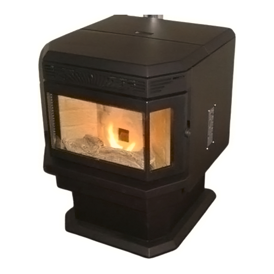
PELLET STOVE
Tasman 40,000
Free Standing
Model
Advertisement
Table of Contents

Related Manuals for Inca Tasman 40,000 Insert

Summary of Contents for Inca Tasman 40,000 Insert
- Page 1 Failure to follow these instructions could result in property damage, bodily injury or even death. Contact your local building officials about restrictions and installation inspection requirements in your area. Save these instructions. Inca Metal Cutting #100 11091 Bridgeport Road Richmond, B.C. V6X 1T3 Canada...
-
Page 2: Table Of Contents
TABLE OF CONTENTS Introduction ..................... 3 Safety Information ..................4 - 5 Specifications ....................6 Dimensions....................6 - 7 Operating Instructions................8 - 12 Thermostat Installation ................. 13 Clearances to Combustibles ..............14 - 15 Installing Your Room Heater..............16 - 24 Mobile Home Installations................25 Insert Pellet Stove ..................26 - 28 Vent Termination Locations ................. -
Page 3: Introduction
(once unit has cooled) and clean the liner and the burn pot. Since Inca Metal has no control over the quality of pellet fuel used in this unit they assume no responsibility for the end users choice in wood pellets. -
Page 4: Safety Information
Do not abuse the glass by striking or slamming the door. Do not attempt to operate the unit with broken glass. Replacement glass must be purchased from an Inca Metal dealer. Do not attempt to clean the glass while unit is hot. To clean the glass, use a soft cotton... -
Page 5: Safety Information .....................................................................................4
SAFETY INFORMATION (continued) Do not operate your stove if you smell smoke coming from it. Turn it off, monitor it and call your dealer. Repair and servicing of your stove may only be done by a qualified technician. Disconnect the power cord before performing any maintenance or repair. NOTE: Turning the stove to "off"... -
Page 6: Specifications
SPECIFICATIONS Heating Specifications: Burn Rate *40,000 btu/hr or 4.8 lbs. of fuel per hour Hopper Capacity .50 lbs. Heating Efficiency ..*75-79% *Depends on quality and heating value of pellet fuel. DIMENSIONS Figure 1... -
Page 7: Dimensions.................................................................................................6
DIMENSIONS The minimum installation dimensions, of the insert opening, are 22 (558.80 mm) wide x 22-3/4 (578 mm) high x 17-1/2 (444.50 mm) deep. Figure 2... -
Page 8: Operating Instructions
OPERATING INSTRUCTIONS Filling the Hopper This pellet stove is available as a freestanding unit or as an insert, therefore there is a different method of filling the hopper for each type of unit. To open the hopper lid, on the insert, pull slightly forward and up. To open the hopper lid on the freestanding unit simply lift up. - Page 9 OPERATING INSTRUCTIONS To Start up a Hot Stove If the stove is warm at re-start, the On/Off button must be pressed down and held for 2 seconds or more until the Heat Level light is lit. When first starting a new pellet stove, or when you completely empty the hopper of pellets, you can press and hold the AUGER button to get the pellets into the burn pot quicker.
- Page 10 OPERATING INSTRUCTIONS Control Board Functions T-STAT/Manual Control: The mode button selects the pellet stove operation to either T-Stat or Manual. Set to Manual to be able to manually select the heat settings and controls. If you have a remote thermostat attached and wish to have the pellet stove controlled by the thermostat, set to T-STAT to operate the pellet stove in variable heat mode.
- Page 11 convection fan speed will also increase with the heat level setting. When the light is flashing during the start up cycle the heat level button will not respond to the adjustments. When the light is solid, indicating the start up cycle is finished, it will then respond (only in manual mode).
-
Page 12: Operating Instructions..............................................................................8
OPERATING INSTRUCTIONS Figure 3 Control Panel Open Door If the door is opened, while the unit is operating, it must be closed within 30 seconds or the unit will go into vacuum error mode. If this happens, close the door, turn the control panel switch to "OFF"... -
Page 13: Thermostat Installation
THERMOSTAT INSTALLATION An optional thermostat is available for use with this unit. A thermostat can help you maintain a constant room temperature. A milli-volt thermostat is required. NOTE: Your thermostat should be installed by an authorized dealer or service person. To Install Thermostat: Disconnect unit from power supply. -
Page 14: Clearances To Combustibles
CLEARANCES TO COMBUSTIBLES INSTALL VENT AT CLEARANCES SPECIFIED BY THE VENT MANUFACTURER. When the unit is being installed on a combustible floor a 1/2" thick non-combustible hearth pad must be installed under the unit. The pad must extend at least the width of the appliance and at least the depth of the appliance plus 6"... - Page 15 CLEARANCES TO COMBUSTIBLES Mantle Clearances to Combustibles A combustible mantle may be installed if its dimensions fall within the chart below. Figure 7 Mantle Depth Mantle Height from Floor 10 (254 mm) 40 (1016 mm) 8-7/8 (222 mm) 39 (991 mm) 7-13/16 (197 mm) 38 (965 mm) 6-11/16 (171 mm)
-
Page 16: Installing Your Room Heater
INSTALLING YOUR ROOM HEATER Your first step is to decide where to install your pellet stove. In order to get the best use of circulated heat we recommend too install it in a large open room centrally located in the house. Next it is very important to check that clearances to combustibles are maintained, these can be found on page 14 &... - Page 17 INSTALLING YOUR ROOM HEATER HORIZONTAL EXHAUST VENT INSTALLATION 1. Locate your appliance in a location which meets the requirements of this manual and where it does not interfere with the house framing, wiring, etc.. 2. Install a non-combustible hearth pad underneath the unit. This pad should extend at least 6 (152 mm) in front of the unit.
- Page 18 HORIZONTAL EXHAUST VENT INSTALLATION (continued) Figure 8 Figure 9...
- Page 19 FREESTANDING INTERIOR VERTICAL INSTALLATION 1. Choose the location for your pellet stove, see item 1 of the Horizontal Exhaust Vent Installation (page 17) for help in determining the correct location. 2. Install the non-combustible hearth pad. 3. Place your pellet stove on the hearth pad and locate the unit in manner that will leave the exhaust vent with a minimum of 3 (75 mm) clearance to any combustible wall.
- Page 20 FREESTANDING EXTERIOR VERTICAL INSTALLATION 1. Follow steps 1 5 from previous page. 2. Locate the center of the exhaust pipe, at the back of the unit. Line up the center with the same spot on the exterior wall a cut a 7 (175 mm) diameter hole through the wall.
- Page 21 SELKIRK DIRECT-TEMP VENT SYSTEM FOR PELLET APPLIANCES Images courtesy of Selkirk...
- Page 22 SELKIRK DIRECT-TEMP VENT SYSTEM FOR PELLET APPLIANCES Images courtesy of Selkirk UP & OUT HORIZONTAL TERMINATION KIT Figure 12...
- Page 23 SELKIRK DIRECT-TEMP VENT SYSTEM FOR PELLET APPLIANCES Images courtesy of Selkirk STRAIGHT OUT HORIZONTAL TERMINATION KIT Figure 13...
- Page 24 SELKIRK DIRECT-TEMP VENT SYSTEM FOR PELLET APPLIANCES Images courtesy of Selkirk THROUGH THE ROOF VERTICAL TERMINATION KIT Figure 14...
-
Page 25: Mobile Home Installations
MOBILE HOME INSTALLATION Mobile home installation should be done in accordance with the Manufactured Home and Safety Standard (HUD), CFR 3280, Part 24. In order for this unit to be installed in a mobile home the following criteria must be met: The unit must be secured to the floor using lag bolts in the holes provided in the pedestal base. -
Page 26: Insert Pellet Stove
INSERT PELLET STOVE The pellet stove is also available as an insert. There is a small amount of assembly required when installing this model. The steps are as follows: Note: The shroud must be installed before unit is set into its final position. Step 1: Shroud Side Facing the back of the unit take the left shroud side piece (no control panel hole) and fasten, as shown, with 2 screws provided. - Page 27 INSERT PELLET STOVE (continued) Step 3: Shroud Top Facing the back of the unit take the top shroud side piece and fasten, as shown, with 4 screws provided. Figure 18 Step 4: Control Board Take the control board and insert it from the back of the right shroud side (facing front of unit).
- Page 28 INSERT PELLET STOVE (continued) Air Inlet Exhaust Cap Installation into a Masonry Fireplace: 1. Have the masonry chimney inspected by a certified chimney sweep or installer to determine its structural Steel Plate or Flashing condition. 2. Determine the amount of venting required to reach the top of the chimney and then add 14 to ensure the termination is an adequate distance above the roofline.
-
Page 29: Vent Termination Locations
Figure 21 VENT TERMINATION LOCATIONS Letter Minimum Clearance Description 24" (60 cm) Above grass, top of plants wood, or any other combustible material. 48" (122 cm) From beside/below any door or window that may be opened. 24" (60 cm) From any door or window that may be opened. 24"... -
Page 30: Maintenance
MAINTENANCE FAILURE TO CLEAN AND MAINTAIN THIS UNIT AS INDICATED MAY RESULT IN POOR PERFORMANCE AND HAZARDOUS SITUATIONS. NEVER CLEAN THE UNIT WHEN HOT. Burn Pot Note: Let the unit cool to room temperature before inspecting the burn pot. Inspect the burn pot regularly to check that the holes have not become plugged. If necessary clean thoroughly. - Page 31 MAINTENANCE - continued Ash Removal - Freestanding Unit If left neglected ashes will eventually fill the ash pan. Remove the ashes periodically to avoid unnecessary ash build up. Ash removal is as follows: 1. Let fire run out and unit cool to room temperature. 2.
- Page 32 MAINTENANCE - continued Cleaning Heat Exchanger Tubes Your unit is designed with a built in heat exchanger tube cleaner. This should be used every 2 or 3 days to remove ash build up on the heat exchanger tubes, which can reduce heat transfer. The handle, for the heat exchanger tube cleaner, is located inside the firebox.
- Page 33 MAINTENANCE - continued Chimney Cleaning: 1. Creosote Formation When wood is burned slowly it produces tar and other organic vapors which combine with expelled moisture to form creosote. The creosote vapors condense in the relatively cool chimney flue, as a result creosote residue accumulates on the chimney lining.
-
Page 34: Optional Accessories
OPTIONAL ACCESSORIES This pellet stove is available with an optional firebox decorative liner as well as a ceramic log set. Decorative Liner Installation: 1. Install the center panel, be sure to line up the hole with the drop tube. 2. Install the left and right panels. Left Panel Right Panel Figure 27... - Page 35 TROUBLE SHOOTING See figure 26, page 32, for component locations. Condition 1: The unit will not light. Check that the unit is plugged in and that the wall outlet has power. Unplug the unit then check all electrical connections against the Wiring Diagram in this manual.
- Page 36 TROUBLE SHOOTING Condition 5: Igniter will not light fuel. Check electrical connections (including fuse) to the igniter. Check the igniter tube, which touches the burn pot, is not plugged with ash. If it is plugged remove the debris (be sure to wait until everything has cooled to room temperature).
- Page 37 TROUBLE SHOOTING Condition 8: The stove will not shut off. Ensure that the room thermostat (if a thermostat is used) is turned down below the room temperature. Disconnect one of the wires to the exhaust temperature sensor, the unit should then shut off.
- Page 38 TROUBLE SHOOTING SARANAC & WESTPOINT PELLET STOVES TROUBLE SHOOTING DURING THE START UP CYCLE: *WE RECOMMEND PUTTING A HANDFUL OF PELLETS IN THE POT WHEN STARTING YOUR PELLET STOVE TO AID WITH IGNITION. Auger motor not feeding: Start up cycle should be 5 second on & 11 seconds off Check wiring is attached properly.
- Page 39 If the fan works then it is NOT a problem with the fan, DO NOT CHANGE THE FAN. Check the low limit switch; wiggle it on start up to see if the fan kicks in. If that does not work then once the stove is warm bypass the low limit switch (see attached Figure 1).
- Page 40 If it does not stop then disconnect power to the stove and plug in fan direct. If it still cycles then it is a bad fan and must be replaced. If it does not cycle when plugged in direct then change the board. TROUBLE SHOOTING DURING THE RUN CYCLE: *THE QUALITY OF PELLETS YOU USE WILL DIRECTLY INFLUENCE THE PERFORMANCE OF YOUR STOVE.
-
Page 41: Troubleshooting
That being said, if the stove continually trips the high limit switch before getting up to unsafe heat then check the convection fan by disconnecting power to the stove and plugging the fan in direct. If the fan cuts out while plugged in direct then change the fan. If the fan runs without fail when plugged in direct then it is not the fan. -
Page 42: Circuit Board Auger Timing
CIRCUIT BOARD AUGER TIMING SARANAC CIRCUIT BOARD #1A MODE: A *8 SECOND CYCLE SETTING TIME ON TIME OFF START UP PIN POSITION LEVEL 1 LEVEL 2 LEVEL 3 LEVEL 4 LEVEL 5 MODE: B (SHOULD SHIP IN THIS MODE) *8 SECOND CYCLE SETTING TIME ON TIME OFF... -
Page 43: Wiring Diagram
WIRING DIAGRAM... -
Page 44: Replacement Parts List
REPLACEMENT PARTS Contact an authorized Inca Metal pellet stove dealer to obtain any of these parts. Never use substitute materials. Use of non-approved parts can result in poor performance and possible safety hazards as well as voiding the Warranty. Item... -
Page 45: Warranty
Inca Metal. With that in mind every stove is fully burned for a minimum of one hour before leaving Inca Metal to ensure the stove is in full working condition. - Page 46 Inca stresses that only high quality premium pellets should be burnt in our stoves! Inca Metal Ltd. is not responsible for the performance of any stove that is being run on poor quality pellets. It is the responsibility of the homeowner to ensure the stove is run on high quality pellets.
- Page 47 Inca Metal neither assumes, nor authorizes any third party to assume, on its behalf, any other liabilities with respect to the sale of this product. Inca Metal will not be responsible for: over firing, downdrafts, spillage howsoever caused and including but not limited to...
-
Page 48: Installation Information Sheet
INSTALLATION INFORMATION SHEET The following page must be filled out by the installer when the unit is installed for warranty purposes and future reference. Failure to properly fill out this sheet will void all future warranties. NAME OF NAME OF OWNER: DEALER: ADDRESS:... -
Page 49: Service And Maintenance Log
INCA METAL PRODUCTS LTD RICHMOND, BC SERVICE AND MAINTENANCE LOG SERIAL # OF STOVE:_______________ DATE SERVICED PERFORMED BY DESCRIPTION OF SERVICE 12/2009...
Need help?
Do you have a question about the Tasman 40,000 Insert and is the answer not in the manual?
Questions and answers
Cross-reference parts list.
The cross-reference parts list for the Inca Tasman 40,000 Insert includes:
- Control panel circuit board: DHC3000/REV-DSVH3001
- Auger motor: 250° F, normally open 611240
- High limit snap disc: 140° F, normally open X-2269F
- Exhaust temperature snap disc
- Convection fan: 7021-10383
- Exhaust fan: 7021-10384
- Vacuum switch: 0.1" w.c. normally open
- Silicone tube for vacuum switch
- Hot rod ignitor
- Door gasket
- Door glass (front panel)
- Door glass (side panel)
- Removable door handle
- Brick panel set (optional)
For replacement parts, contact an authorized Inca Metal pellet stove dealer.
This answer is automatically generated
Cross reference departs list
The cross-reference parts list for the Inca Tasman 40,000 Insert includes:
- Control panel circuit board: DHC3000/REV-DSVH3001
- Auger motor: 250°F, normally open 611240
- High limit snap disc: 140°F, normally open X-2269F
- Exhaust temperature snap disc
- Convection fan: 7021-10383
- Exhaust fan: 7021-10384
- Vacuum switch: 0.1" w.c. normally open
- Silicone tube for vacuum switch
- Hot rod ignitor
- Door gasket
- Door glass (front panel)
- Door glass (side panel)
- Removable door handle
- Brick panel set – optional
For replacement parts, contact an authorized Inca Metal pellet stove dealer. Use only approved parts to avoid performance issues, safety hazards, and warranty voiding.
This answer is automatically generated