Table of Contents
Advertisement
@Copyright 1996
All Rights Reserved.
Manual second edition Nov.10,1996
The information in this document is subject to change without prior notice
in order to improve reliability, design and function and does not represent
a commitment on the part of the manufacturer.
In no event will the manufacturer be liable for direct, indirect, special,
incidental, or consequential damages arising out of the use or inability to
use the product or documentation, even if advised of the possibility of such
damages.
This document contains proprietary information protected by copyright. All
rights are reserved. No part of this manual may be reproduced by any
mechanical, electronic, or other means in any form without prior written
permission of the manufacturer.
Trademarks
SSC-5x86H is registered trademarks of Acquire Inc., PC/104 is
trademarked of PC/104 Consortium, IBM PC is a registered trademark of
International Business Machines Corporation. Intel is a registered
trademark of Intel Corporation. AMI is registered trademarks of American
Megatrends, Inc. Other product names mentioned herein are used for
identification purposes only and may be trademarks and/or registered
trademarks of their respective companies.
SSC-5x86H Ver.C
Super 5x86H Half-sized
Single Board Computer
Advertisement
Table of Contents

Related Manuals for Vox Technologies SSC-5x86H

Summary of Contents for Vox Technologies SSC-5x86H
- Page 1 Trademarks SSC-5x86H is registered trademarks of Acquire Inc., PC/104 is trademarked of PC/104 Consortium, IBM PC is a registered trademark of International Business Machines Corporation. Intel is a registered trademark of Intel Corporation.
-
Page 3: Table Of Contents
1. Introduction..............3 Specifications..................4 What You Have..................5 2. Installation..............6 SSC-5x86H Ver.C Layout ..............6 Jumper Description ................8 CPU setting of SSC-5x86H Ver.C ............9 Watch-Dog Timer.................10 DiskOChip Flash Disk .................11 PS/2 Mouse Setting................11 3. Connection ..............12 Floppy Disk Drive Connector ...............12 IDE Disk Drive Connector..............13 Parallel Port ..................13... - Page 4 PS/2 Mouse Port .................16 3.10 PC/104 Connection Bus ...............16 4. AWARD BIOS Setup..........18 Getting Start ..................18 Standard CMOS Setup .................20 BIOS Feature Setup................21 Chipset Feature Setup ................22 Power management Setup..............23 Appendix A. Watch-Dog Timer........25...
-
Page 5: Introduction
The PCC supports multiple low power down modes. In addition, the SSC-5x86H provides two 72-pin SIMM sockets for its on-board DRAM. The 72-pin accepts 1MB, 2MB, 4MB, 8MB, 16MB, and 32MB SIMM. So, the total on-board memory can be configured from 1MB to 64MB. -
Page 6: Specifications
1.1 Specifications : The SSC-5x86H Super 5x86 Half-sized Single Board Computer provides the following specification: • CPU : 486SX/DX/DX2/ DX4 or Cyrix/AMD 5x86 • : ISA bus and PC/104 bus • DMA channels : 7 • Interrupt levels : 15 •... -
Page 7: What You Have
1.2 What You Have In addition to this User's Manual , the SSC-5x86H Ver.C package includes the following items: • SSC-5x86H Ver.C Super 5x86 Half-sized SBC • Printer Cable • FDD/HDD Cable • 6-pin Mini-Din to 5-pin Din Keyboard Adapter Cable If any of these items is missing or damaged, contact the dealer from whom you purchased the product. -
Page 8: Installation
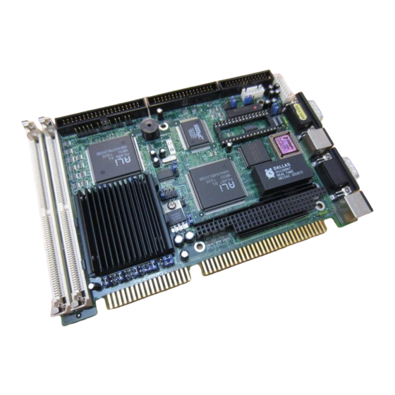
Installation This chapter describes how to install the SSC-5x86H. At first, the layout of SSC-5x86H is shown, and the unpacking information that you should be careful is described. The jumpers and switches setting for the SSC-5x86H's configuration, such as CPU type selection, system clock setting, and interrupt IRQ setting for serial ports and parallel port, are also included. -
Page 10: Jumper Description
2.2 Jumper Description You can change the SSC-5x86H's configuration by setting jumper switches on the board. The board's jumpers are preset at the factory. Under normal circumstances, you should not need to change the jumper settings. A jumper switch is closed (sometimes referred to as shorted with the plastic cap inserted over two pins of the jumper). -
Page 11: Cpu Setting Of Ssc-5X86H Ver.c
2.3 CPU setting of SSC-5x86H Ver.C f you want to upgrade the CPU, you must do two things: 1. Set the jumpers for CPU type. 2. Adjust the jumpers setting for CPU speed. • CPU Type Setting: CPU Type Intel DX4 &E... -
Page 12: Watch-Dog Timer
Because right now in the market have several kind of CPUs using different voltage in core logic. For example the AMD offers 486DX2-66/80 and DX4-100/120 at 3.3V,Intel offers DX4-75/100 at 3.3V,and some Cyrix CPU will use 3.45V. CPU Voltage JP13 * +3.3V +3.45V (*) : default setting... -
Page 13: Diskochip Flash Disk
M-Systems. The DOC have two models in market ED1102 (28-pin) and ED1202(32-pin). The two models DOC can be used in SSC-5x86H Ver.C board. Because the DOC is 100% compatible to hard disk and DOS. Customer don’t need any extra software utility to use it. It is just “plug and play”,easy and reliable. -
Page 14: Connection
Connection This chapter describes how to connect peripherals, switches and indicators to the SSC-5x86H board. 3.1 Floppy Disk Drive Connector SSC-5x86H board comes equipped with a 34-pin daisy-chain driver connector cable. • CN6 : FDC CONNECTOR PIN NO. DESCRIPTION PIN NO. -
Page 15: Ide Disk Drive Connector
HDC CS0# HDC CS1# HDD ACTIVE# GROUND 3.3 Parallel Port This port is usually connected to a printer, The SSC-5x86H includes an on-board parallel port, accessed through a 26-pin flat-cable connector CN9. • CN9 : Parallel Port Connector PIN NO. -
Page 16: Serial Ports
GROUND IOW# GROUND GROUND 3.4 Serial Ports The SSC-5x86H offers two high speed NS16C550 compatible UARTs with Read/Receive 16 byte FIFO serial ports. • CN12 & CN14 : Serial Port DB-9 Connector( ACE0 & ACE1) PIN NO. DESCRIPTION DATA CARRIER DETECT (DCD) -
Page 17: External Switches And Indicators
PIN-NO DESCRIPTION HDD ACTIVE# 3.7 External Power Connector The SSC-5x86H has an on-board external power connector CN11. You can connect power directly to the CPU board for some single- board-computer( without passive backplane) application. • CN11 : EXTERNAL POWER CONNECTOR PIN NO. -
Page 18: External Speaker
GROUND +12V 3.8 External Speaker The SSC-5x86H has its own buzzer, you also can connect to the external speaker through the connector CN3. • CN3 : Speaker Connector PIN NO. DESCRIPTION SPEAKER SIGNAL GROUND 3.9 PS/2 Mouse 6-pin Mini-DIN Connector •... - Page 19 ( CN7 = 64-pin female connector; CN8 = 40-pin female connector.) J1 / P1 J1 / P1 J2 / P2 J2 / P2 Row A Row B Row C Row D IOCHECK* SBHE* MEMSC16* RESETDRV LA23 IOSC16* LA22 IRQ10 IRQ9 LA21 IRQ11 LA20...
-
Page 20: Award Bios Setup
AWARD BIOS Setup The SSC-5x86H uses the AWARD PCI/ISA BIOS for system configuration. The AWARD BIOS setup program is designed to provide maximum flexibility in configuring the system by offering various options which may be selected for end-user requirements. This chapter is written to assist you in the proper usage of these features. -
Page 22: Standard Cmos Setup
4.2 Standard CMOS Setup The Standard CMOS Setup is used for basic system hardware configuration. Every time when you change any hardware configuration,for example memory size,you have to modify this setup again. Please refer the following screen for this setup. Mode Setting for >528MB IDE HDD When the IDE hard disk drive you are using is larger than 528MB,please set the HDD mode to LBA mode. -
Page 23: Bios Features Setup
4.3 BIOS Features Setup This setup is designed for customer‘s tuning best performance of the SSC-5x86H board. As for normal operation customers don‘t have to change any default setting.The default setting is pre-setted for most reliable operation. Virus Waring : Enable - Will halt system when any attempt to write to boot sector or patition table of hard disk. -
Page 24: Chipset Features Setup
above address,you could enable the shadow to get higher operation performance.When you enable the shadow function,it will also reduce the memory available by between 640KB and 1024KB. 4.4 Chipset Features Setup This setup functions are almostly working for ChipSet(ALI M1489 and M1487). -
Page 25: Power Management Setup
Onboard Serial Port 2 : COM2/2F8(default),COM3/3F8,COM4/2E8,Diabled COM1/3F8 Onboard Parallel Port : 378H/IRQ7(default),278H/IRQ5,3BCH/IRQ7,Disabled 4.5 Power Management Setup Power Management Setup help user handles the SSC-5x86H board‘s “green” function. The features will shut down the video display and hard disk to save energy. - Page 26 Power Management : This is the master control of all power management functions. The default setting is “disable” for general application. User Defined : Allows user to set any power saving options. Min. Saving : System enters power saving mode after 1 hour no activity.
-
Page 27: Appendix A. Watch-Dog Timer
card and also let the screen blank. PM Timers : User can set the HDD Power Down,Doze Mode,Standby Mode, and Suspend Mode‘s time out period. The system will be recovered when the system is re-activity. PM Events : If there is any activity occured on the list of the group,the system will wake up. - Page 28 been set to 10 seconds, the I/O port 443H must be read within 7 seconds. Note: when exiting a program it is necessary to disable the Watch- Dog Timer, otherwise the system will reset.
- Page 29 REM EXAMPLE PROGRAM REM WATCH-DOG TIMER == WDT GOSUB 5000 REM ENABLE AND REFRESH THE WDT GOSUB 1000 REM TASK 1, 2 SECS GOSUB 5000 REFRESH THE WDT GOSUB 2000 REM TASK 2, 3 SECS GOSUB 6000 REM DISABLE THE WDT GOSUB 3000 REM TASK 3, 5 SECS GOSUB 5000 REM ENABLE AND REFRESH THE WDT GOTO 30...
Need help?
Do you have a question about the SSC-5x86H and is the answer not in the manual?
Questions and answers