Chapters
Table of Contents

Summary of Contents for matev FPS-JD 4020
- Page 1 GmbH Nürnberger Str. 50 90579 Langenzenn T +49 (0) 9101 9087 -0 F +49 (0) 9101 9087 -20 info@matev.eu www.matev.eu Original Operating Manual Front hitch FPS-JD 4020 Implements for John Deere 4020 Version 12/2009...
-
Page 2: Table Of Contents
Contents Table of contents About this operating manual ..................3 Safety ..........................4 Intended use ........................4 Qualification of personnel ....................4 General safety instructions ....................4 Special safety instructions ....................5 Installation ........................6 Mounting the front power lift ..................... 6 Installing and removing the front PTO shaft .............. -
Page 3: About This Operating Manual
About this operating manual About this operating manual Dear customer! Thank you for purchasing these implements for the John Deere 4020, we appreciate your trust. Prior to using these implements for the first time read this operating manual carefully and conscientiously all the way through. Keep this operating manual where it is easily accessible in the vicinity of the imple- ments. -
Page 4: Safety
Safety Safety Guidelines and instructions with which you must comply are summarized in this sec- tion. Personnel who install, operate and maintain the implements for the John Deere 4020, must have read and understood this operating manual. Intended use The implements should only be mounted on the John Deere 4020. All other uses are excluded. -
Page 5: Special Safety Instructions
Safety Attention! Injuries can occur. Wear protective work clothing. Special safety instructions Safety instructions are specified in this chapter that are also affixed as stickers on the implements Attention! Danger of injury due to moving parts. Remove the ignition key before performing maintenance tasks on the implement. -
Page 6: Installation
Installation Installation Danger! Severe injury to the operator or third parties occurs. Switch off the tractor and remove the ignition key before mounting or dismounting the implements. Note! & Enter the chassis number of the front power lift on page 33 of this operat- ing manual. -
Page 7: Fig 2: Adapt The Cooling Line
Installation Note! & If you have unscrewed the two screws (see), do not move the tractor until you have retightened these screws. On both sides, unscrew the screws marked in Fig 1: Adapt the cooling line from the front axle. This makes it easier to fasten the base frame onto the tractor. Attention! Danger of injury due to falling frame parts. -
Page 8: Fig 3: Mounted Base Frame, Right
Installation Fig 3: Mounted base frame, right Fig 4: Mounted base frame, left Firmly tighten the four fastening screws of the front axle. Page 8... -
Page 9: Fig 5: Mount The Upper Link Receptacle
Installation Fig 5: Mount the upper link receptacle Mount the upper link receptacle on the tractor frame by bolting it to the two base frames (4 screws on each side) Mount the hydraulic cylinders and the hydraulic hoses as follows: Fig 6: Left hydraulic cylinder mounted Mount one hydraulic cylinder on the left side viewed from the direction of travel. -
Page 10: Fig 7: Right Hydraulic Cylinder Mounted
Installation Fig 7: Right hydraulic cylinder mounted Mount the second hydraulic cylinder on the right side. Secure each bolt with a screw. Fig 8: Hydraulic hose, left 10. Lay out the hydraulic hoses of the left hydraulic cylinder to the rear, behind the exhaust. -
Page 11: Fig 9: Hydraulic Hose, Left Rear
Installation Fig 9: Hydraulic hose, left rear 11. Continue to lay out the hydraulic hoses further to the rear so that they can be routed around the engine block on the right side of the tractor. In this process fas- ten the lines with cable ties at a suitable point. -
Page 12: Fig 11: Hydraulic Hose, Right
Installation Fig 11: Hydraulic hose, right 13. Lay out the lines from the hydraulic connection of the tractor to the T-piece. En- sure that the stop valve is in the lift line (lines to the bottom of the cylinders). Attention! Ensure that the hydraulic system is connected properly. -
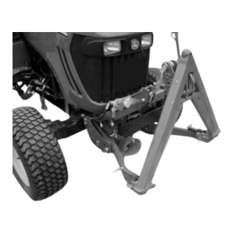
Page 13: Fig 13: Arm With Bolt
Installation 3.1.2 Mounting attachment kit cat. 1 Note! & The coupling triangle is not part of the scope of delivery of the extension kit cat. 1 but is available as optional equipment. Fig 13: Arm with bolt Fig 14: Arms mounted Insert the arms into the lift arm. -
Page 14: Fig 15: Fasten The Arms To The Lift Arm
Installation Fastening bolt Bolt for pendulum Fig 15: Fasten the arms to the lift arm Secure the arms on both sides with the supplied bolts (see Fig 15). Insert the bolts and fasten them tightly with the screws. Insert the bolts for the pendulum compensation in one of the provided bores, de- pending on whether you want to drive with or without pendulum compensation. -
Page 15: Fig 17: Catch Hooks On The Arms Of The Lift Mechanism
Installation Catch Fig 17: Catch hooks on the arms of the lift mechanism Pull back the lock bolt on the catch hook and arrest it by twisting it. Lift the coupling triangle into the catch hooks on the arms of the lift mechanism. Fig 18: Upper link fastened on the coupling triangle Fastening the upper link on the coupling triangle. -
Page 16: Fig 19: Upper Link Up, Secured
Installation Fig 19: Upper link up, secured 3.1.3 Mounting extension kit cat. 0 Upper link Triangl Arms Fig 20: Scope of delivery, cat. 0 Insert the arms into the lift arm. Secure the arms on both sides with the supplied bolts. Insert the bolts and tighten them with the lock screws (see extension kit cat. -
Page 17: Installing And Removing The Front Pto Shaft
Installation Insert the bolts for the pendulum compensation in one of the provided bores, de- pending on whether you want to drive with or without pendulum compensation. For this see section 4.1.3. Mount the upper link on the upper link receptacle. Mount the coupling triangle on the lift arms. -
Page 18: Fig 22: Drive Shaft
Installation 3.2.2.1 Mounting the drive shaft Attention! Danger of injury due to rotating parts. Switch off the tractor and remove the ignition key. Comply with the warnings in the documentation provided with the uni- versal joint shaft. Drive shaft Rear holder Fig 22: Drive shaft Mounting the rear holder on the tractor frame. -
Page 19: Fig 23: Rear Holder For Drive Shaft
Installation Fig 23: Rear holder for drive shaft Fig 24: Rear suspension Hook the drive shaft into the holder with the rear suspension. On the front, hook the drive shaft into the lift mechanism with the front holder, flip up the bracket, until the locking pin engages. 3.2.2.2 Dismounting the drive shaft Attention! -
Page 20: Fig 25: Front Suspension In The Tractor
Installation Locking pin or screw Fig 25: Front suspension in the tractor With one hand push against the eccentric bracket, this offloads the lock bolt (or screw). With the other hand unlock the lock bolt or unscrew the screw. Move the eccentric bracket downward until it is offloaded. Unhook the drive shaft front and rear. -
Page 21: Mounting The Attachment Kit For The Mower
Remove the coupling triangle before mounting the attachment kit. & Lower the mower. Dismount the fork pieces from the original mower attachment parts. Mount these fork pieces on the mower attachment parts supplied by matev. Move the front lift downward. Page 21... -
Page 22: Mounting The Front Hydraulic Extension Kit
Install the hydraulic hose on the side of the tractor. Connect the hydraulic system to sockets 1 and 2 of the tractor's hydraulic system. Mounting the front guard The holders for the front guard are matev accessories. The ram bracket is an original John Deere part. Note! If a hydraulic front extension kit is already mounted, the hydraulic cou- &... -
Page 23: Fig 28: Scope Of Delivery - Front Guard Holder
Installation Fig 28: Scope of delivery - front guard holder Mount the front guard holder on the upper link receptacle left and right. Mount the front guard on the holders. Fig 29: Front guard with hydraulic extension mounted Fit on the hydraulic couplings if a front extension kit was mounted, in the right holder, as viewed from the direction of travel. -
Page 24: Operation
Operation Operation Front power lift with front load operation Note! Before the front loader can be used, you must dismount the coupling & triangle and the lift arms. cat 0: For this version, in addition you must dismount the upper link part. The front loader can be mounted and operated as described by John Deere. -
Page 25: Fig 30: Sticker - Lowering Safeguard
Operation Attention! Danger of crushing due to moving parts. Never reach into the crushing hazard danger area, if parts are still moving or can move. Comply with the instruction in the operating manual. Affix the provided sticker on the vehicle where it is easily visible in the vicinity of the stop valve. -
Page 26: Fig 33: With Swing Compensation
Operation Attention! Damage to the tractor or the implements can occur. Release the lowering safeguard before activating the hydraulic system of the front power lift. 4.1.3 Working with and without pendulum compensation Thanks to the integrated pendulum compensation on the front power lift you can easily drive on uneven paths, roads or pastures. -
Page 27: Adjusting The Mower
Operation Adjusting the mower Attention! For a correct cut you must set the mower correctly. The important thing in this regard is that the mower must be lower in the front than it is in the rear. Note! & See the operating manual from John Deere on information concerning adjustment of the mower. -
Page 28: Maintenance
The implements must be disposed of in accordance with the applicable regulations of the municipality or the country. Take the parts to the collection points for residual waste, special waste, or recycle them depending on material. matev GmbH does not provide any disposal services. Page 28 of 31... -
Page 29: Technical Data
This information is on the type plate of the device. Article number: ............. chassis number ............Warranty The matev GmbH "General Terms and Conditions" provide information on the war- ranty and guarantee conditions. matev GmbH Nürnberger Str. 50 90579 Langenzenn... -
Page 30: List Of Illustrations
List of illustrations List of illustrations Fig 1: Adapt the cooling line ........................6 Fig 2: Adapt the cooling line ........................7 Fig 3: Mounted base frame, right ......................... 8 Fig 4: Mounted base frame, left ........................8 Fig 5: Mount the upper link receptacle......................9 Fig 6: Left hydraulic cylinder mounted ...................... -
Page 31: Ec Declaration Of Conformity
Nürnberger Str. 50 90579 Langenzenn declares that the machine Front Power lift Type FPS-JD 4020 131 5735 complies with the provisions of the Machinery Directive 2006/42/EC and with the implementing national statutory provisions. The signer is authorized to compile the technical documents.
Need help?
Do you have a question about the FPS-JD 4020 and is the answer not in the manual?
Questions and answers