Table of Contents
Advertisement
Quick Links
Advertisement
Table of Contents

Subscribe to Our Youtube Channel
Summary of Contents for DRAKE 4000 series II
- Page 2 Every endeavour has been made to ensure that information, details and descriptions set out in this literature are correct at the time of going to press. However Drake is unable to guarantee that no changes have subsequently taken place to the specification or characteristics of, or relating to any Drake product, after the publication of this literature.
- Page 3 WARNING Electrical shock can cause severe personal injury or death. All major units of this equipment are powered by mains voltage. Unless specifically advised otherwise, DISCONNECT mains supply before carrying out any maintenance or repair tasks. 4000 Digital Series ,, INSTALLATION GUIDE STA0379 - Issue 1.4 Page iv of xii...
-
Page 4: Glossary Of Terms
GLOSSARY OF TERMS Analogue to Digital Converter Assignment, Diagnostics and Monitoring Standard co-axial video connector CODEC Coder/Decoder CMAPSi Configuration and Master Assignment Programming System integrated Conference Facility configured by CMAPSi, similar to older Party Line sys- tems. Central Switching Unit Digital to Analogue Converter Direct Access Key Decibel... - Page 5 Normally Closed Normally Open Non Intrusive Download NVRAM Non-Volatile Random Access Memory Output Printed Circuit Board Pot. Potentiometer Power Supply Unit Random Access Memory Rear Connector Unit Root Mean Square Standard Rack Unit (19 inches wide x 1.75 inches high or 482.6mm x 44.45mm) Side tone Side tone is the audio, which is heard in the Headset’s ear-...
- Page 6 Consult the named Drake document for further details. Contact Drake for suitable options. Tips given. 4000 Digital Series ,, INSTALLATION GUIDE Page vii of xii STA0379 - Issue 1.4...
- Page 7 4000 Digital Series ,, INSTALLATION GUIDE STA0379 - Issue 1.4 Page viii of xii...
-
Page 8: Table Of Contents
TABLE OF CONTENTS TABLE OF CONTENTS ....................ix 1. INTRODUCTION .....................1 1.1 System Overview ....................1 2. GETTING STARTED ....................3 2.1 Unpacking the Equipment .................3 2.2 Installation ......................3 2.2.1 General Information ...................3 2.2.2 Installing a System ..................4 2.2.3 Hot Insertion of Matrix Cards ..............4 2.2.4 Pass Codes ....................4 3. - Page 9 4.2.1 PD4215 - 16 Key Control Panel (1RU) ............49 4.2.2 PD4217 - Intelligent Control Panel (1RU) ..........50 4.2.3 PD4211 LCD Key Panel (1RU) ..............52 4.2.4 PD4212 LCD Key and Rotary Encoder Panel .........53 4.2.5 PD4224 - Intelligent Control Panel (2RU) ..........55 4.2.6 PD4225 - Router Control Panel (2RU) ............56 4.2.7 PD4226 - 32 Key Control Panel (2RU) ............58 4.2.8 PD4221 - LCD Key Panel (2RU) .............60...
- Page 10 7.3.2 PDE4537 Audio Interface ................88 7.4 Matrix to PC Download Cable .................89 7.5 PD3901 Beltpack Interface ................89 7.5.1 Installation Information ................90 8. INTRODUCTION TO DRAKE SYSTEM NETWORKING ........93 8.1 Overview ......................93 8.2 General System Requirements ...............94 8.2.1 Personal Computer Attachment ...............95 8.3 Installation .......................95...
- Page 11 4000 Digital Series ,, INSTALLATION GUIDE STA0379 - Issue 1.4 Page xii of xii...
-
Page 12: Introduction
The crosspoints in the matrix are activated or de-activated according to configuration rules held in the system’s Matrix map (stored in the microprocessor’s memory). The system map for the 4000 Series II residing on a Personal Computer is downloaded into the Matrix from the ’Configuration and Master Assignment Programming System integrated’... - Page 13 Connection to other 4000 Series II systems can also be achieved by use of Ethernet, providing an integrated private intercom network. Up to eight 4000 Series II systems can be connected using this facility. A Conference facility is also available, configured via CMAPSi, which allows people to converse in a conference mode.
-
Page 14: Getting Started
The physical and electrical requirements for each part of the system are detailed in this guide. Drake recommends the use of a Fan Tray, such as the Drake PD3704, with the 9RU frames as forced cooling is required. WARNING Risk of electrical shock. -
Page 15: Installing A System
2.2.4 Pass Codes The 4000 Series II matrices have a passcode to enable system sizes and features bought with your system. The pass code is supplied either inside the front door of the 4RU or 9RU matrix and/or on the purchase documentation. -
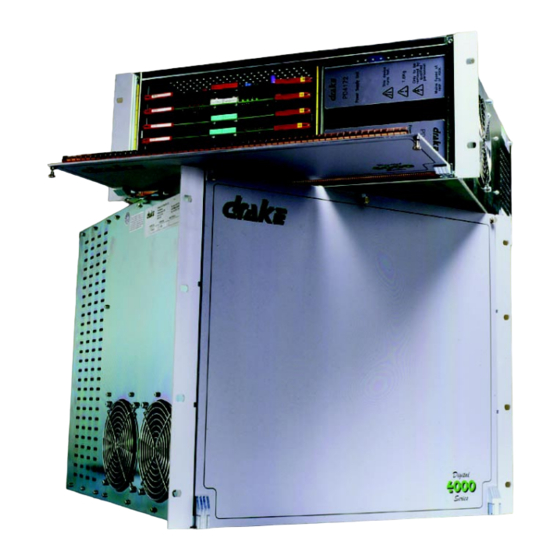
Page 16: Matrix Description
Forced air cooling, with a 2U gap above the unit is required to maintain the unit at the correct operating temperatures. Drake recommends the use of a Fan Tray, such as the Drake PD3704. Inadequate or obstructed ventilation may result in serious damage to the system. - Page 17 PDE4622 CODEC RCU, PDE4628 Serial Communications RCU and PDE4619 GPI RCU. The position of these cards is set at build time and recorded in the System Configuration. The card mnemonic and Drake part number are printed onto the 4000 Digital Series ,, INSTALLATION GUIDE STA0379 - Issue 1.4...
-
Page 18: Matrix Rear Connections And Facilities
centrally mounted handle of each card. The slot number into which the card fits is printed onto a label mounted on the top ejector handle of the card. 3.1.1.5 Matrix Power Supply Slots Four power supply slots are provided at the bottom of the rack and are accessible from the front. -
Page 19: 4420 - 4Ru Digital Matrix Frame
3.1.2.4 IEC Mains Inlet Two of these are provided for redundant power operation. Each one is rated at 90V to 250V, 50Hz - 60Hz, 300W maximum. Prior to connection check that the correct fuses are present in the fuse holders as indicated above. 3.2 4420 - 4RU Digital Matrix Frame 3.2.1 Overview The 4420 Series matrix comprises a 4U by 19 inch rack mount unit with all connections... - Page 20 3.2.1.2 Rear View RCU Slot 7 RCU Slot 1 RCU Slot 6 Mains Fuse 1 RCU Slot 5 EC Mains Inlet 1 RCU Slot 4 Earthing point RCU Slot 3 Mains Fuse 2 RCU Slot 2 EC Mains Inlet 2 4000 Digital Series ,, INSTALLATION GUIDE Page 9 of 107...
- Page 21 RCU. The position of these cards is set at build time and recorded in the System Configuration. The card mnemonic and Drake part number are printed onto the centrally mounted handle of each card. The slot number into which the card fits is printed onto a label mounted on the top ejector handle of the card.
-
Page 22: Matrix Rear Connections And Facilities
3.2.1.5 Matrix Power Supply Slots Two power supply slots are provided on the right of the rack and are accessible from the front. Both supplies are identical and both are used for redundancy. Mains Inlet 1 operates with the top supply and Mains Inlet 2 operates with the bottom supply. The PDE4172 supplies are used in this frame to provide +/-5V and +/-12V. - Page 23 Table 1: Matrix Card Types NUMBER TYPE FUNCTION PDE4622 CODEC RCU Rear Connector Unit for CODEC Card with (PDE4622 = electronic, connection for up to 16 audio inputs and out- PDE4622tx = TXF) puts via D-Type connectors. PDE4628 Serial Communications Rear Connector Unit for CODEC Card with connection for up to 16 audio and 16 RS232/ 422 data inputs and outputs via 16 RJ45 con-...
-
Page 24: Pde4642 - Microprocessor Card
3.3.1 PDE4642 - Microprocessor Card The PDE4642 provides the centralised functions of command, control and communications, within the 4000 Series II System. It is used in conjunction with the PDE4643 Rear Connector Unit (RCU). Blue Black Grey PDE4642 Microprocessor Card and Coloured Reset Buttons 3.3.1.1 Card Location... - Page 25 3. PDE4642 Processor LEDs The group of five LEDs, MGB [red], M/C [red], IPC [yellow], D16 [yellow] and OK [green] operate as follows: LED TYPE STATE DURING BOOT ASSIGNMENT IN MAIN CODE On when processor card is master. On, while downloading or On when external communications waiting for download of code.
- Page 26 LED. WARNING - Any local panel programming is also lost throughout the whole system. 4. Grey Push button - Not in use Reserved for Drake diagnostic purposes. 4000 Digital Series ,, INSTALLATION GUIDE Page 15 of 107...
-
Page 27: Pde4643 - Microprocessor Card Rcu
5. Bootstrapping Press the red, blue and black push-button on the Processor Card(s). Then release the red button while still pressing the blue and black buttons. When the green LED begins to flash, release the blue and black buttons. Control Panels will have firmware downloaded from the Master Processor Card. This process is known as bootstrapping. - Page 28 Table 4: PDE4643 - GPI Inputs (Optional) Description Pin Number GPI Input 1 GPI Input 2 GPI Input 3 GPI Input 4 GPI Input 5 GPI Input 6 GPI Input 7 GPI Input 8 GPI Input 9 GPI Input 10 GPI Input 11 GPI Input 12 Isolated Inputs (requires external +7...
- Page 29 Table 5: PDE4643 - GPI Outputs (Optional) Description Pin Number Relay Output 1 P Relay Output 1 N/C Relay Output 1 N/O Relay Output 2 P Relay Output 2 N/C Relay Output 2 N/O Relay Output 3 P Relay Output 3 N/C Relay Output 3 N/O Relay Output 4 P Relay Output 4 N/C...
- Page 30 Table 6: PDE4643 - AUI Description Pin Number Control Input Screen Control Input + Data Output + Data Input Screen Data Input + DC Power 0V Control Input - Data Output - Data Output Screen Data Input - DC Power +12V DC Power Screen Table 7: PDE4643 - Ethernet RJ45 Description...
-
Page 31: Pde3601B Digital Matrix Card
3.3.3 PDE3601B Digital Matrix Card The function of the PDE3601B is to route digital audio inputs to an output. This is achieved by combining inputs with variable gains applied at each crosspoint. Each card carries four ‘ routers’ which are identical routing and mixing processors. At least one of these cards is required in the Matrix and there are no RCUs associated with it. -
Page 32: Pde4606B - 16 Channel Panel Communications Card
The following table details the function of the PDE3601B card LEDs: Table 9: PDE3601A LEDs 5 Volts On if + 5 Volts is present 5 Volts On if - 5 Volts is present Quick flash = Normal operation Status Slow flash = indication of problem with any one of the four audio processors on the card. -
Page 33: Pde4616 - 16 Channel Panel Communications Card Rcu
3.3.4.1 Card Locations These cards may be located in any slot from 3 to 20 in the 4920 matrix, or any slot from 2 to 7 in the 4420 matrix. 3.3.4.2 Controls and Indicators The following table details the function of the PDE4606B card LEDs: Table 10: PDE4606B LEDs Panel 1 connected and returning valid handshake Panel Status... -
Page 34: Pde4621 - 16 Channel Audio Input / Output Codec Card
Description Pin number Data Core Return Screen 3.3.5.1 Card Location These cards may be located in any RCU slot from 3 to 20 in the 4920 matrix, or any RCU slot from 2 to 7 in the 4420 matrix. However, these RCUs must be fitted in a RCU slot directly behind a PDE4606B Panel Communications Card. - Page 35 VOX Channel 1 VOX Channel 16 3.3.6.1 Card Location These cards may be located in any slot from 3 to 20 in the 4920 matrix, or any slot from 2 to 7 in the 4420 matrix. 3.3.6.2 Controls and Indicators Three LEDs are mounted on the leading edge of the board;...
-
Page 36: Pde4631 - 16 Channel Audio Input / Output Codec Card
be set up prior to shipping and should need no further adjustment. The nominal threshold setting is -20dB. The level controls (single-turn potentiometers) are mounted in two rows on the leading edge of the board, below the handle. The pots are numbered and correspond to the inputs, but as a guide channel 1 is the top most pot. - Page 37 Table 12: PDE4631 LEDs Green +5 Volts On if +5 Volts present. Green -5 Volts On if -5 Volts present. Green Configured On if the card is recognised by the system as valid for this position 3.3.7.1 Card Location These cards may be located in any slot from 3 to 20 in the 4920 matrix, or any slot from 2 to 7 in the 4420 matrix.
-
Page 38: Pde4622/Pde4622Tx - 16 Channel Codec Card Rcu
A block diagram of the CODEC card is shown below. PDE4622 RCU 16-bit A/D Audio Input 1 of 16 (Transformer Optional) PING 16-Bit Source Bus 16 to 1 PONG Clocks Control Mixing VME Control Timeslot Detect Register PING PDE4622 RCU 8-Bit Destination Bus 1 to 16 DEMUX... -
Page 39: Audio Connections
3.3.8.2 Audio Connections PDE4622/PDE4622TX - Output 1 to 8: Description Pin number Output 1 + Output 1 - Output 1 Screen Output 2 + Output 2 - Output 2 Screen Output 3 + Output 3 - Output 3 Screen Output 4 + Output 4 - Output 4 Screen Output 5 +... - Page 40 PDE4622/PDE4622TX - Input 1 to 8 Description Pin number Input 1 + Input 1 - Input 1 Screen Input 2 + Input 2 - Input 2 Screen Input 3 + Input 3 - Input 3 Screen Input 4 + Input 4 - Input 4 Screen Input 5 + Input 5 -...
-
Page 41: Pde4628 - 16 Channel Serial Communications Rcu
3.3.9 PDE4628 - 16 Channel Serial Communications RCU The PDE4628 is a 16-channel serial communications rear connector unit (SCRCU) for use with a CODEC board within the 4000 Series II system. The communications standard is RS422 for each channel. A 4920 matrix can hold up 12 PDE4628 board pairs and therefore support 192 serial data link channels. - Page 42 Matrix U29 and U30 3.3.9.1 Card Location These cards may be located in any RCU slot from 3 to 20 in the 4920 matrix, or any RCU slot from 2 to 7 in the 4420 matrix. However, these RCUs must be fitted in a RCU slot directly behind a PDE4621 CODEC Card.
- Page 43 3.3.9.3 Power On Self Test On power up, the SCRCU will conduct a series of power on self-tests. While this is taking place, the SCRCUs matrix of 35 LEDs will indicate the current test, as indicated by the following characters: Table 13: PDE4628 Self-Tests Display Test (Appears for 1 second)
- Page 44 LED (off) - indicates that the channel is unused. LED flashing - indicates an error on that channel. The PDE4628 provides 16-channel communication with the 4000 Series II matrix via an RS422 interface. The pin-out configuration for the sixteen RJ45 connectors (CON 1-16) is indicated in the following section.
-
Page 45: Pde4619 - General Purpose Interface Rcu
3.3.9.4 Data and Audio Connections PDE4628: RS422 Channels 1-16 Table 14: RJ45 Connector Description Pin Number Data Receive (Rx+) Data Receive (Rx-) Audio Input (+) Audio Output (+) Audio Output (-) Audio Input (-) Data Transmit (Tx+) Data Transmit (Tx-) 3.3.10 PDE4619 - General Purpose Interface RCU The PDE4619 RCU contains all necessary interface logic to provide 32 opto-isolated inputs and 32 outputs, 20 of which are relay contact closures and the remaining 12 are... - Page 46 Input Display Output Display 3.3.10.1 Card Location These cards may be located in any RCU slot from 3 to 20 in the 4920 matrix, or any RCU slot from 2 to 7 in the 4420 matrix. However, these RCUs can only be fitted in a free RCU slot.
- Page 47 Table 15: PDE4619 Channel Status Input Display (Indicates the channel status of the 32 channels. Channel 1 is top left. Channel 32 is bottom right) Output Display (Indicates the channel status of the 32 channels. Channel 1 is top left. Channel 32 is bottom right) Input Display (Indicates the DC supply is OK) Output Display...
- Page 48 3.3.10.2 PDE4619 - GPI Connections CON 1 - GPI Inputs 1 to 32 Description Pin number GPI Input 1 GPI Input 2 GPI Input 3 GPI Input 4 GPI Input 5 GPI Input 6 GPI Input 7 GPI Input 8 GPI Input 9 GPI Input 10 GPI Input 11...
-
Page 49: Installation Guide
PDE4619 - GPI Outputs 1 to 12 Description Pin number Relay Output 1 P Relay Output 1 N/C Relay Output 1 N/O Relay Output 2 P Relay Output 2 N/C Relay Output 2 N/O Relay Output 3 P Relay Output 3 N/C Relay Output 3 N/O Relay Output 4 P Relay Output 4 N/C... - Page 50 PDE4619 - GPI Outputs 13 to 32 Description Pin number Relay Output 13 P Relay Output 13 N/C Relay Output 13 N/O Relay Output 14 P Relay Output 14 N/C Relay Output 14 N/O Relay Output 14 P Relay Output 15 N/C Relay Output 15 N/O Relay Output 15 P Relay Output 16 N/C...
-
Page 51: Pde4609 - 8 Channel Telephone Card Rcu
The PDE4609 card is used to interface the control of the Telos Telephone Balance Unit with the 4000 Series II system and has two functions: • Control outputs for seizing its line and disabling the Auto Answer facility of the Hybrid. - Page 52 3.3.11.1 Card Location This card must be located in any RCU slot from 3 to 20 in the 4920 matrix or any RCU slot from 2 to 7 in the 4420 matrix. 3.3.11.2 PDE4609 - Connectors Description Pin number Auto A Drop A Code 3A Code 2A...
- Page 53 Eight LEDs are mounted on the leading edge of the board; they give indication of the card status. 4000 Digital Series ,, INSTALLATION GUIDE Page 42 of 107 STA0379 - Issue 1.4...
- Page 54 Matrix. For example, to activate Telos unit 1, a matrix crosspoint is programmed to activate GPI Output Card 5, pins 1 and 9 (see the following table). Contact Drake Handbook for further details and Digital Telephone Hybrid Interface options...
- Page 55 In a two card system, to activate Telos unit 9, a matrix crosspoint is programmed to activate GPI Output Card 9, pins 1 and 9 (see the following table) Table 18: PDE4609 - Telos Operation - Units 9-16 Telos Unit Auto-Answer Disable Line Seize Number...
- Page 56 or 17 to 31 of GPI cards 5 to 8 for Telos units 1 to 8 respectively. E.g. If a caller on Telos unit 4 dials an acceptable security code followed by 07, then GPI card 6, pin 23 is actuated and can be programmed to access a route or conference, light a panel LED, etc.
-
Page 57: Matrix Power Supplies
S2 controls the card function as Telos 1-8 or 9-16. 3.4 Matrix Power Supplies 3.4.1 4420 (4U) Matrix PD4172 Power Supply The supply requirements of the 4420 Matrix are met with the following type of power supply unit (PSU). Two of the units can be fitted for supply redundancy. The top PSU is served by Mains Inlet 1 and the bottom supply by Mains Inlet 2. -
Page 58: 4920 (9U) Matrix Pd4173 Power Supply
3.4.2 4920 (9U) Matrix PD4173 Power Supply The supply requirements of the 4920 Matrix are met with the following type of power supply unit (PSU). Up to four of the units can be fitted in the matrix for supply redundancy. The two units on the left of the matrix are served by Mains Inlet 1 and the two units on the right are served by Mains Inlet 2 for AC redundancy. -
Page 59: Power Supply Redundancy
3.4.3 Power Supply Redundancy The following table allows system power supply redundancy to be understood. A ’small system’ is considered to be one that draws less than 20A from the +5V PSU and a ‘ large system’ is considered to be one that draws 20A or more from the +5V PSU. The total current can be calculated by referring to the table and calculating the total system load. -
Page 60: Control Panel Description
4. CONTROL PANEL DESCRIPTION 4.1 Overview The 4000 Series II Control Panels comprise of a range of 1RU and 2RU by 19 inch rack mount units. The standard connection of these panels is via CAT5 (RJ45) cabling to connect analogue audio and RS422 data from the Control Panel to the PDE4628 Serial Communications RCU located in the Matrix. -
Page 61: Pd4217 - Intelligent Control Panel (1Ru)
• Designation strip for key identification (printed from CMAPSi) 4.2.1.1 Front View Microphone Connector Headset Connector 4.2.1.2 Rear View Earth Connection Matrix Comms Connector (BNC) (Optional) DC Power Connector (DIN) Extension Panel Connector Control I/O (Optional) Matrix Comms Connector (RJ45) Audio I/O (Optional) 4.2.2 PD4217 - Intelligent Control Panel (1RU) The PD4217 - Intelligent Control Panel Level Control Panel has the following features:... - Page 62 • Microphone gain, headset gain and side-tone are software configurable • Headset connector with pushbutton select 4.2.2.1 Front View Microphone Connector Headset Connector NOTE: Microphone is shown here for illustrative purposes only. Contact Drake for details of suitable products. 4.2.2.2 Rear View Earth Connection Matrix Comms Connector (BNC) (Optional)
-
Page 63: Pd4211 Lcd Key Panel (1Ru)
4.2.3 PD4211 LCD Key Panel (1RU) The PD4211 - LCD Key Panel has the following features: • 12 centrally programmed tri-colour LCD keys, including reply • Shift button allows access to another 11 programmable LCD keys • Soft button for local programming of pushbutton assignments •... -
Page 64: Pd4212 Lcd Key And Rotary Encoder Panel
NOTE: Microphone is shown here for illustrative purposes only. Contact Drake for details of suitable products. 4.2.3.2 Rear View Earth Connection Matrix Comms Connector (BNC) (Optional) DC Power Connector (DIN) Extension Panel Connector Control I/O (Optional) Matrix Comms Connector (RJ45) Audio I/O (Optional) 4.2.4 PD4212 LCD Key and Rotary Encoder Panel... - Page 65 Reply Key Loudspeaker Direct Access Key (DAK) Headset Select Pushbutton Headset Socket NOTE: Microphone is shown here for illustrative purposes only. Contact Drake for details of suitable products. 4.2.4.2 Rear View Earth Connection Matrix Comms Connector (BNC) (Optional) DC Power Connector (DIN)
-
Page 66: Pd4224 - Intelligent Control Panel (2Ru)
4.2.5 PD4224 - Intelligent Control Panel (2RU) The PD4224 - Intelligent Control Panel has the following features : • 32 programmable pushbuttons, including reply, locally and centrally programmable • Dual row alphanumeric displays (4 or 8 character choice) • Shift button allows access to another 32 programmable pushbuttons •... -
Page 67: Pd4225 - Router Control Panel (2Ru)
4.2.5.1 Front View Microphone Connector Headset Connector NOTE: Microphone is shown here for illustrative purposes only. Contact Drake for details of suitable products. 4.2.5.2 Rear View Earth Connection Matrix Comms Connector (BNC) (Optional) DC Power Connector (DIN) Extension Panel Connector... - Page 68 • LS cut facility • Rotary encoder for crosspoint level control • DTMF Dial facilities with electronic keypad included • Programmable pushbuttons for talk, listen, talk & listen, talk & forced listen and dual talk & listen functions • Connection for Key Extension Panels for IFB Sources and for Level Control Panels for port Input and Output level control •...
-
Page 69: Pd4226 - 32 Key Control Panel (2Ru)
4.2.6.2 Rear View Earth Connection Matrix Comms Connector (BNC) (Optional) DC Power Connector (DIN) Extension Panel Connector Control I/O (Optional) Matrix Comms Connector (RJ45) Audio I/O (Optional) 4.2.7 PD4226 - 32 Key Control Panel (2RU) The PD4226 -Control Panel has the following features: •... - Page 70 4.2.7.1 Front View Microphone Connector Headset Connector 4.2.7.2 Rear View Earth Connection Matrix Comms Connector (BNC) (Optional) DC Power Connector (DIN) Extension Panel Connector Control I/O (Optional) Matrix Comms Connector (RJ45) Audio I/O (Optional) 4000 Digital Series ,, INSTALLATION GUIDE STA0379 - Issue 1.4 Page 59 of 107...
-
Page 71: Pd4221 - Lcd Key Panel (2Ru)
4.2.8 PD4221 - LCD Key Panel (2RU) The PD4221 - LCD Key Panel has the following features: • 24 centrally programmed tri-colour LCD keys, including reply • Shift button allows access to another 23 programmable LCD keys • Soft button for local programming of pushbutton assignments •... -
Page 72: Pd4222 - Lcd Key And Rotary Encoder Panel (2Ru)
NOTE: Microphone is shown here for illustrative purposes only. Contact Drake for details of suitable products. 4.2.8.2 Rear View Earth Connection Matrix Comms Connector (BNC) (Optional) DC Power Connector (DIN) Extension Panel Connector Control I/O (Optional) Matrix Comms Connector (RJ45) Audio I/O (Optional) 4.2.9 PD4222 - LCD Key and Rotary Encoder Panel (2RU) - Page 73 Reply Key Loudspeaker Direct Access Key (DAK) Headset Select Pushbutton Headset Socket NOTE: Microphone is shown here for illustrative purposes only. Contact Drake for details of suitable products. 4.2.9.2 Rear View Earth Connection Matrix Comms Connector (BNC) (Optional) DC Power Connector (DIN)
-
Page 74: Pd4222S - Supervisor Panel
4.2.10 PD4222S - Supervisor Panel The PD4222S Supervisor Panel has the same features as a standard PD4222 LCD Key Panel, plus the following additions: • Mimics and controls any target panel in the local system (including crosspoint lev- els and configuration data) •... - Page 75 4.2.11.1 Front View Microphone Connector Headset Connector 4.2.11.2 Rear View DC Connector Matrix Comms Connector (RJ45) Matrix Comms Connector (BNC) (Optional) Audio I/O (Optional) Fibre Optic / Digital CAT5 Connector (Optional) Control I/O (Optional) 4000 Digital Series ,, INSTALLATION GUIDE Page 64 of 107 STA0379 - Issue 1.4...
-
Page 76: Extension Panels
PANEL connector at the rear of the associated Control Panel. Switch off the power before connecting or disconnecting the panel. The maximum cable length between a 4000 Series II Control Panel and the Level Control Panel is 1.5 metres. NOTE: The 4203 Extension Panel cannot be connected to any the range of LCD key panels or the PD4217 control panel. -
Page 77: 4206 - 20 Key Extension Panel (1Ru)
PANEL connector at the rear of the associated Control Panel. Switch off the power before connecting or disconnecting the panel. The maximum cable length between the 4206 and a 4000 Series II Control Panels is 1.5 metres. NOTE: The 4206 Extension Panel cannot be connected to any the range of LCD key panels or the PD4217 control panel. - Page 78 4.3.2.1 Front View 4.3.2.2 Rear View Extension Connector 4.3.2.3 Programming/Configuration A hexadecimal-encoded rotary switch on the Extension Panel card sets the panel address for the benefit of the main control panel. The default position for the extension panel when fitted with standard software is at position 0. Rotary Switch Table 25: 4206 DAK Mapping Rotary Switch Position...
-
Page 79: Custom Control Panels
4.4 Custom Control Panels 4.4.1 PD4216 - Custom Panel Interface (1RU) The PD4216 - Custom Panel Interface has the following features: • Audio facilities include microphone output, level control • Control signals sent to the custom panel through a serial interface •... -
Page 80: Pde3531 Custom Panel Card
4.4.1.4 Installation Information The microphone/s and volume pot/s should be wired with good quality 7/0.2 screened cable over a maximum distance of 25m. The control interface can be connected to the remote panel with a cable run of up to 20m using 15-way screened cable or 15-way screened ribbon cable. - Page 81 LED display cable runs (from CON4 on the D section) can be up to 1m long and should be contained within the same panel box as the PCB to maintain EMC compliance. SL/D to SL/D connections (from CON1 on the SL section) should be a maximum of 150mm using a screened ribbon cable.
- Page 82 Assembly Diagram: PDE 3531 Connector Assignments Yellow LEDs Switches From P/SL/D to SL/D isplay 15 way D-type from PDE 3156 To SL/D Red LEDs 4000 Digital Series ,, INSTALLATION GUIDE Page 71 of 107 STA0379 - Issue 1.4...
- Page 83 LED (yel- CON 5 (y), CON 6 (r) LEDs 1-8 low/red) Switch CON 7 Switches Drake Keypad Switch Mapping For PDE 3531 Cards Card 1 Card 2 PDE 3531 PDE 3531 SOFT Notes: 1. 2 PDE 3531 cards are required for ke operation, with S1 set up as LHS (100 and RHS (0000).
- Page 84 4000 Digital Series ,, INSTALLATION GUIDE Page 73 of 107 STA0379 - Issue 1.4...
-
Page 85: Panel Connections
Fibre optic or coaxial connection with a Series 2 control panel is made possible by fitting the PDE4536 options card. A standard female BNC type connector is used to connect 4000 series II panels to a 4000 series II matrix. This is isolated to avoid earth potential variations. -
Page 86: Pde4537 Options Card
Description Pin Reference Signal Core Return Screen 4.5.5 PDE4537 Options Card For information on the PDE4537 options card, go to “PDE4537 Options Card” on page 87. 4000 Digital Series ,, INSTALLATION GUIDE Page 75 of 107 STA0379 - Issue 1.4... -
Page 87: I2C Serial Interface Connector
4.5.6 I C Serial Interface Connector This 15-way D-Type connector is only supported on the PD4216 Custom Panel Interface. The connector provides the I C Serial Interface for connecting to the PDE3531 Custom Panel Cards, for custom applications. Description Pin number Clock Data Interrupt... -
Page 88: Extension Connector
Intkey / +5 Volts Select / Note: Maximum total cable length between a 4000 Series II Control Panel and PD4203 or PD4206 Extension Panels is 1.5 metres The Connector on the PD4203 and PD4206 Level Control and Extension Panels are equipped with a plug rather than a socket. -
Page 89: Dc Power Adaptor Connector
4.5.9 DC Power Adaptor Connector This 4-pin DIN connector is used to connect the Drake-supplied 150/UNI and 151/UNI DC Power Adaptors. The pin-out of the 4-pin DIN Power connector is as follows: Description Pin number Positive Power Negative Power 4.5.10 DC Power Adaptor Ratings The 150/UNI and 151/UNI DIN power adaptors are supplied for DC panel applications. -
Page 90: Commissioning
5.1.2 Hot Insertion of Matrix Cards All 4000 Series II Euro-cards and power supplies may be inserted or removed without causing damage. However, ’hot’ insertion of cards may cause the system to reset; this is not serious but will ’lock’ the system’s operation for a brief preset initialisation period. -
Page 91: Control Panels
5.2 Control Panels 5.2.1 Mains Supply Some 4000 Series II control panels have an un-switched IEC inlet located at the rear of each unit. Before applying power, check that the voltage selector is set to the correct supply voltage and that the fuses fitted are of the correct rating for that voltage. See section on fuse details. - Page 92 4000 Digital Series ,, INSTALLATION GUIDE Page 81 of 107 STA0379 - Issue 1.4...
-
Page 93: Normal Operation
Check the operation of the headset connection with a test headset. 5.5 Hardware Configuration Other than software configuration, there are a limited number of user-adjustable controls on the 4000 Series II system. Most rack and panel cards have optional link settings. Contact Drake Sales Department for further information. -
Page 94: System Programming
4000 Series II rack. Any subsequent expansion of the system, must be either pre-configured or will require a new configuration map (normally supplied with the expansion kit). -
Page 95: Cabling
7.2 Control Panel Wiring 7.2.1 Solid conductor coaxial cable Each control panel requires a single cable connection to the 4000 Series II Matrix using 75 Ohm co-axial cable (see above for details). Lay in these cables as required and terminate both ends in male BNC connectors as shown. -
Page 96: Rj45-Terminated Cabling
NOTE: Matrix to panel connection by co-axial cabling requires any Series 2 panel to be fitted with a PDE4536 Coax/Fibre Optic options card. 7.2.2 RJ45-Terminated Cabling CAT5 cabling has a variety of uses and configurations with Drake equipment. Pin-out information is given in the following tables. Each cable length should not exceed 1000m. - Page 97 7.2.2.2 Remote Panel Crossover Usage • Between remote panel and remote TA Table 30: CAT5 Remote Panel Crossover Pin Number Pin Number Wire Colour W/Blu W/Bn 7.2.2.3 Ethernet Crossover Usage • PC direct to TA (not via hub) Table 31: CAT5 Ethernet Crossover Pin Number Pin Number Wire Colour...
-
Page 98: Pde4537 Options Card
7.3 PDE4537 Options Card The Panel Options Card, which can be fitted to any standard Series 2 Control Panel, provides additional control and audio interfaces. These allow the panel to be locally customised. The card provides the following functions: 7.3.1 PDE4537 Control Interface External Control Interfaces provide up to four opto-isolated control inputs and two double-pole changeover relays. -
Page 99: Pde4537 Audio Interface
7.3.2 PDE4537 Audio Interface The audio interface provides two balanced audio inputs and two balanced audio outputs. A 9-way D-type socket is used. Input 1 (MMI, Mix Mix In) is mixed directly into the microphone audio path to the matrix. Input 2 (AUX, Aux Mix In) is mixed onto the loudspeaker path via the AUX volume control on the control panel. -
Page 100: Matrix To Pc Download Cable
7.4 Matrix to PC Download Cable Serial downloads of data between the matrix and PC use a cable terminated with 9-way D-type connectors. 7.5 PD3901 Beltpack Interface The PD3901 is a 1U x 19” mains powered Interface Rack. The Interface can accommodate up to four beltpack rings (for BPS1010 beltpacks) with programme sound, for connection to and from DRM 3200, 3400 and 3600 matrices. -
Page 101: Installation Information
The Unit is supplied equipped for two rings as standard. The components to add additional rings to, a maximum of four, can be added as required. Each ring can have up to 10 beltpacks connected to it. Access is provided to drive the call lamps on the beltpacks. Similarly the call-detect outputs from the beltpacks are available for external switching use, etc. - Page 102 Audio Output Connections The ring connections are via 6 way XLR sockets and he call inputs and call detect outputs are available on a 9-way D-Type socket The pin-outs for both are given below: 4000 Digital Series ,, INSTALLATION GUIDE Page 91 of 107 STA0379 - Issue 1.4...
- Page 103 GPI (Call Detect / Call Pin No Beltpack Ring No D- Input Connection) Connection type XLR6 Ring 1 Screen 0v (ring A) Ring 2 +36v Ring 3 Audio ring A Ring 4 Call I/Ps (Connect Audio ring B to Gnd (Pin5, 0v) to action) Gnd 0v +36v...
-
Page 104: Introduction To Drake System Networking
8.1 Overview Drake System Networking enables up to eight separate Drake DCS 3000, 4000 and 4000 Series II Intercom Systems to be connected together by an Ethernet network and dedicated audio trunk lines. The Ethernet network connects each System via Ethernet Interfaces; these pass network configuration and operational information between systems. -
Page 105: General System Requirements
All network addressing is installed in each Ethernet Interface, containing unique Ethernet addresses supplied by Drake. This allows the Processor card in each system to retrieve the Ethernet address assigned to that system. Note that when CMAPSi is attached to the network via Ethernet it will have its own manufacturer’s network... -
Page 106: Personal Computer Attachment
Coaxial cable, of the correct type, for connection between Systems is also required, as follows: Table 32: Function/System/Card Allocation DCS 3000/4000 4000 Series II Function Card Series System System GPI/Ethernet Control PDE6650 GPI/Ethernet Transceiver PDE3619A/E Ethernet Control PDE4642 Ethernet Transceiver PDE4643 Thin Ethernet - 50W impedance (Belden 3907 or RG58 or equivalent). - Page 107 SW1-2 SW1-5 SW1-8 SW1-3 SW1-6 NOTE: LK1 and LK2 on the PDE 6650 card are NOT installed for normal network operation. PDE 3619A/E Card Settings The link settings to be used for this card are shown on the next page. PDE 3619A/E - Link Positions Switch SW1 should be set as follows: SW1-1 and -4...
-
Page 108: 4000 Series Ii
AUI Drop Cable The standard AUI Drop cable connector is a 15-way D-type. A special cable must be used, wired as shown in the following table. This cable can be supplied by Drake upon 4000 Digital Series ,, INSTALLATION GUIDE Page 97 of 107 STA0379 - Issue 1.4... -
Page 109: Audio Networks
request. The cable used should be suitable for IEEE802.3 AUI connection and of the type Belden 9903, BICCH9611 or Brand Rex BE57903. Table 33: AUI Connections 9-Way Male 15-Way Female Signal Name Wire Colour D-Type D-Type +12V NOTE: This cable has two isolated screens. One screen serves as an overall protective screen;... -
Page 110: System Specifications
9. SYSTEM SPECIFICATIONS Table 34: System Specifications Size 9RU - 4920: 482mm (19 inches) wide 400mm (9RU) high 500mm (20 inches) deep 4U - 4420: 482mm (19 inches) wide 168mm (4RU) high 485mm (19.5 inches) deep Weight: 20 to 35kg Power Requirements: 90V to 250V, 50/60Hz, 300W max Frequency Response:... - Page 111 Table 34: System Specifications Output Impedance 120Ω Output Balance <-30dBu Linearity ±1dB GPI Inputs: 37-way D-type Opto-isolated GPI Outputs: 37-way D-type Isolated relay Open col- lector driver Control Inputs/Outputs: 9-way D-type RS232, 9-way D-type RS422, 10Base-T Ethernet® 15-way D-type AUI AC power Inputs/Outputs 4920: 2x IEC AC input, XLR4 DC Output...
- Page 112 CAT5 1000m max. using specified cable. Coaxial 500m max. (1600 feet) using specified cable Network 8 systems from 3000 or 4000 Series II. Standard Ethernet® connection 4000 Digital Series ,, INSTALLATION GUIDE Page 101 of 107 STA0379 - Issue 1.4...
- Page 113 Table 34: System Specifications Panel to Extension panel 25-Way D-type plug, Screened 25-Way Ribbon Cable PC download (RS232/422 users): max. RS232 - 10m cable lengths are determined by the RS422 - 100m cable type used and the total capaci- tance supported by each link. Values given here are typical.
- Page 114 Table 34: System Specifications Network Application As above, plus: Note: Drake Intercom Systems are designed to be used on a private dedi- 8 bit Ethernet Card (100% IEEE 802.3 cated Local Area Network (LAN) compatible) System Operating Temperature 0-40ºC Range System Storage Temperature Range -55º...
- Page 115 4000 Digital Series ,, INSTALLATION GUIDE STA0379 - Issue 1.4 Page 104 of 107...
-
Page 116: Index
INDEX Numerics ......................69 3531 Custom Panel Card ........................43 3609 LED functions ......................... 96 3619A/E link positions ......................... 65 4003 Gain Adjustment ....................65 4203 - Level Control Panel (1RU) ..................... 66 4206 - 20 Key Extension Panel (1RU) ...................... - Page 117 ........................16 GPI Daughter Card ........................ 36 GPI RCU LED Matrices ....................... 82 Hardware Configuration ........................4 Hot Insertion of Cards ......................4 Hot Insertion of Matrix Cards ....................... 76 I2C Serial Interface Connector ..........................3 Installation ......................72 Keypad mapping, PDE 3531 ........................
- Page 118 ..............22 PDE4616 - 16 Channel Panel Communications Card RCU ..................34 PDE4619 - General Purpose Interface RCU ..............23 PDE4621 - 16 Channel Audio Input / Output CODEC Card ..............27 PDE4622/PDE4622TX - 16 Channel CODEC Card RCU ................30 PDE4628 - 16 Channel Serial Communications RCU ..............
Need help?
Do you have a question about the 4000 series II and is the answer not in the manual?
Questions and answers