Table of Contents
Advertisement
Advertisement
Table of Contents

Related Manuals for Frontier V6

Summary of Contents for Frontier V6
- Page 1 Owners Manual V6 Mid Wheel Drive all models With Dynamic G90 controller Page 1...
- Page 2 www.magicmobility.com.au YouTube: MAGIC MOBILITY OZ Page 2...
-
Page 3: Table Of Contents
Reaching and Bending ..................11 3.15 Prescription Drugs/Physical Limitations ..............11 3.16 Alcohol/Smoking ....................11 Specifications .........................12 The Frontier ......................12 Standards testing .....................12 Operating Instructions ....................13 Performance adjustments ..................13 Positioning .......................13 Freewheel Mode – pushing the power chair ............13 Electrical Safety Protection ..................14 Seat Tilt Option –... - Page 4 Care & Maintenance ......................21 General Guidelines ....................22 Batteries ........................22 Tyres and Castors ....................22 8.3.1 Tyre Inflation .....................22 8.3.2 Tyre Wear ......................23 Upholstery .......................24 Cleaning ........................24 Corrosion Protection ....................24 8.6.1 Paint scratches and chips .................24 8.6.2 Beach, salt water and Coastal Areas..............25 8.6.3 Snow and Ice, Salted Roads and Footpaths ............25 8.6.4...
-
Page 5: Power Wheelchair Owner's Manual
1 Power Wheelchair Owner’s Manual Thank you for choosing a Magic Mobility Product. We are proud of the quality construction of every chair we build. This owner’s manual explains the operation of your new chair. Please read it carefully as it contains important safety, care and maintenance information. Magic Mobility’s Power Wheelchair series may be custom made to measure and may vary in detail from chair to chair however this owners manual should cover all basic features and options. -
Page 6: Safety And Damage Warnings
Magic Mobility Dealer before operating the wheelchair. Buying the Frontier V6 opens up a whole new World and we are keen for you to explore new possibilities. However, we strongly recommend that when learning your driving capabilities, the capabilities of your wheelchairs and learning where potential hazards may be;... -
Page 7: Motor Vehicle Transport
Ensure footrests are swung away or removed For side transfers ensure armrests and legrests are swung away or removed, position yourself as far back as possible in the power chair seat to prevent the power chair from tipping forward. WARNING! Avoid putting all your weight on either armrests or footrests. -
Page 8: Public Streets And Roadways
Public Streets and Roadways WARNING! You should not operate your power chair on public streets and roadways. This is in accordance with local traffic laws, which vary by country. Please check your local traffic laws. Be aware that it may be difficult for traffic to see you when you are seated on your power chair. -
Page 9: Maximum Recommended Incline
When climbing an incline, try to keep your power chair moving; however do not use excessive speed. If you must stop, start up again slowly and then accelerate cautiously. if at anytime you feel uncomfortable, reduce your acceleration rate. When driving down an incline, set your power chair to the slowest speed setting and drive in the forward direction only. -
Page 10: Removable Parts
Figure 2 – 1 in 14 Gradient Removable Parts STOP! Do not attempt to lift or move a power chair by any of its removable parts (armrests, legrest, backrest). This may result in personal injury and/or damage to the chair. 3.10 Cornering Information Excessively high cornering speeds can create the possibility of tipping. -
Page 11: Positioning Belts
Appendix B – Electromagnetic Interference (EMI) Your power chair’s performance may be influenced by electromagnetic fields caused by mobile telephones or other radiating devices, such as hand-held radios, radio and television stations, wireless computer links, microwave sources, and pagers. Your power chair may also be a source of electromagnetic and radio frequency interference. Be aware that your power chair may affect the performance of alarm systems and other radiating devices. - Page 12 WARNING! It is strongly recommended that you do not smoke cigarettes while seated in your wheelchair. The power chair has passed the necessary flammability requirements, but it is strongly advised to keep ashtrays at a safe distance from seat cushions, to ensure cigarettes are completely extinguished before disposal, and we strongly advise against leaving lit cigarettes unattended.
-
Page 13: Specifications
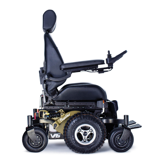
4 Specifications The Frontier A Frontier power chair is depicted below. This Figure 3 will help you identify some of the features referred to throughout this manual. Headrest Backrest Armrest Joystick Seat Footrest Rear Castors Drive Wheels Power Base Front... -
Page 14: Operating Instructions
5 Operating Instructions The speed and direction of the power chair is controlled with by the joystick Turn on your power chair (see section Error! Reference source not found.) Use the joystick to control the speed and direction of travel At times, particularly during high acceleration on inclines, not all of the 4 castor wheels will contact the ground. -
Page 15: Electrical Safety Protection
Don’t forget to push the levers back in again firmly after manually positioning the chair WARNING! Do not use your chair in freewheel mode or attempt to place your chair into freewheel mode without an attendant present. You may cause injury to yourself and to others. -
Page 16: Ansi/Resna Wc/Vol 1 - Section 19 And Iso7176-19 Restraint System; If Fitted
Push the ‘Accessory Mode Selection’ button on the DX2. Select power elevating seat by moving the joystick left or right. Once the power elevating seat option is highlighted (as shown to the right), moving the joystick forward or backwards will operate the function. ... -
Page 17: Joystick Controls
6 Joystick controls A detailed manual for the DX2 joystick is available from Dynamic Control’s website: www.dynamiccontrols.com. The joystick controls may be customised and may be one of a number of different models depending upon users requirements. This manual contains detailed information on the standard joystick control. -
Page 18: Hand Control Joystick Operation - Figure 3 - G90A
Hand control joystick operation – figure 3 – G90A Hand Controller DXREMG90A 6.5.1 On/Off Button To turn the power on press the On/Off button. The current battery charge will be indicated and the System Status LED will illuminate and not flash. Press the On/Off button again to turn the power off. -
Page 19: Left Indicator (If Lights Are Fitted)
6.5.4 Left Indicator (If Lights Are Fitted) To turn the Left Indicator on/off, press and release (‘short press’) the Left Indicator button. To toggle the Headlights on/off, press and hold (‘long press’) the Right Indicator button. 6.5.5 Mode Each press of the Mode button will increment the drive profile, up to the maximum configured value and then back to profile The current drive profile will be shown in the 7 Segment Display. -
Page 20: Lighting Menu Mode - If Fitted (Not Standard)
6.5.7 Lighting Menu Mode – If Fitted (Not Standard) When in Lighting Menu Mode, the 7 Segment display shows 3 horizontal lines. Moving the joystick forward will toggle the Headlights. Moving the joystick left will toggle the Left turn Indicators. Moving the joystick right will toggle the right turn Indicators. -
Page 21: Charging
6.5.10 Charging Fig3-16 Plug the battery charger into the charging socket located at the front of the G90 Remote. Driving is inhibited while the system is being charged as denoted by ‘-‘ displayed on the 7 segment display. However, it is possible to use accessory functions e.g. actuators. -
Page 22: Public Transportation
The following procedure is valid for the recommended charger brand - consult your separate charger instructions if supplied with an alternative charger. 1. Ensure the wheelchair is turned off. 2. Always make sure that the charger is turned off before plugging it into the wheelchair. 3. -
Page 23: General Guidelines
STOP! Do not use parts, accessories, or adapters other than those authorised by Magic Mobility. This may void your warranty and cause damage to your power chair. General Guidelines Avoid exposing your power chair to any type of moisture where possible (rain, snow, mist, salt water, or wash). -
Page 24: Tyre Wear
Mid Drive Tyres 12 ½ x 2 ¼ HD 40 psi 36 psi (Compact 73, 40, (248kPa) pneumatic 275 kPa supercompact) Castors (Compact 36 psi 36 psi 200mm Pneumatic (248kPa) series) 248 kPa Castors 250mm Pneumatic 36 psi 36 psi (All terrain and (248kPa) 248 kPa... -
Page 25: Upholstery
Corrosion Protection The V6 power chair has been manufactured using a range of processes that have been developed to resist corrosion. Although all effort has been made to ensure the long-term durability of the product we cannot guarantee that the wheelchair will remain corrosion-free for the duration of its usable life. -
Page 26: Beach, Salt Water And Coastal Areas
8.6.2 Beach, salt water and Coastal Areas Salt water and the surrounding environment is highly corrosive. Exposure to coastal areas will also increase the likelihood of corrosion occurring on the power chair even if it is not used on the beach. Coastal air generally has a far higher salt content than inland areas. -
Page 27: Transportation
WARNING! Corrosive chemicals are contained in the batteries. Use only AGM or gel-cell batteries to reduce the risk of leakage or explosive conditions. Transportation Always be sure your power chair and its components are properly secured when it is being transported. -
Page 28: Fault Finding
Set-Up of the Electronic Control Unit is to be performed ONLY by individuals authorised by Magic Mobility. The final tuning adjustments of the controller may affect other activities of the wheelchair. STOP! If non-certified individuals perform any work on these units, the warranty is void and damage to the equipment could occur. -
Page 29: Electromagnetic Interference (Emi) From Radio Wave Sources
Note if the batteries are allowed to discharge completely, they may not recharge (section 0 in the event of this happening please contact your Magic Mobility Dealer for assistance. 10.5 Electromagnetic Interference (EMI) From Radio Wave Sources Powered Wheelchairs may be susceptible to electromagnetic interference (EMI), which is interfering electromagnetic energy (EM) emitted from a variety of sources. -
Page 30: Technical Specifications
Appendix B – Electromagnetic Interference (EMI). 11 Technical Specifications Product Magic Mobility Frontier V6 Standard – 182kg Weight Capacity Seat elevator or tilt fitted - 155 kg Maximum Speed 10km/h (6.2mph) 40km (25.5 miles) (73Ah gel cell batteries, dependent on... -
Page 31: Warranty
12 Warranty 12.1 Warranty policy This wheelchair is provided with a 12 month Limited Warranty on the parts and workmanship contained within. This warranty does not cover: wear and tear, tyres, batteries, upholstery freight to, or from, the manufacturer, that is, the chair must be returned to the factory or Dealer, freight pre-paid, for all warranty repairs. -
Page 32: Head Office And Operations
13 Head Office and Operations 2/112 Browns Road Noble Park, Vic. 3174 Australia Phone: +61 3 8791 5600 Fax: +61 3 9701 0144 Email Address: admin@magicmobility.com.au Website: http://www.magicmobility.com.au © Copyright Magic Mobility 2014 Page 32... -
Page 33: Appendix A - Ansi/Resna Wc/Vol 1 - Section 19 & Iso7176-19 Restraint System; If Fitted
Backrest: Upright i.e. at or close to 90° to the seat Rear Tie Down Rear Tie Down Front Tie Down Front Tie Down Figure 5 - V6 Tie Down Locations There are four wheelchair securement points; two at the front and two at the rear. Page 33... - Page 34 The tie downs have a rectangular aperture 25mm x 50mm. Any hook or loop of the restraint end fitting must fit through this hole. The wheelchair provides for anchoring a pelvic belt restraint that conforms to the requirements of RESNA WC19 Section 19 and ISO7176-19. The belt anchor points are shown in Figure 5.
- Page 35 Figure 7 - Preferred and optimal zones for angles of pelvic belt restraints The belt restraint buckle of three point belt restraints must be placed in contact with the occupant’s body and away from wheelchair components Upper torso belt restraints should fit directly over, and in contact with, the middle of the shoulder.
- Page 36 Figure 9 - Illustration of proper routing an positioning of belt restraints on the wheelchair occupant Belt restraints should be adjusted as snugly as possible, consistent with user comfort. Belt restraints should not be worn or twisted in a manner that reduces the area of contact of the belt webbing with the occupant This wheelchair has the following ratings if WC4-19/ISO7176-19 tie downs are fitted Ease of proper belt positioning: Excellent...
- Page 37 in motor vehicles should be used to reduce the risk of serious injuries to wheelchair occupants Alterations or substitutions should not be made to the wheelchair or seating system structural members, or to its parts and components, without consulting the wheelchair manufacturer The use of postural pelvic belts attached to the wheelchair base or seat frame is encouraged during travel, but these belts should be positioned so they don’t interfere with the proper positioning of crashworthy belt restraints and...
- Page 38 Vehicle interior components that cannot be removed from the clear zones of Error! Reference source not found., or that are near the wheelchair occupant space at a level that may be contacted by a wheelchair occupant’s head during a side impact collision or a vehicle rollover, should be padded with material that complies to FMVSS 201.
- Page 39 For people who use heavy wheelchairs transportation in larger vehicles is recommended when the option exists The wheelchair should be inspected by a manufacturer’s representative before reuse following involvement in any type of collision Care should be taken when applying the occupant restraint to position the seatbelt buckle so that the release button will not be contacted by wheelchair components during a crash Page 39...
- Page 40 Page 40...
-
Page 41: Appendix B - Electromagnetic Interference (Emi)
Appendix B – Electromagnetic Interference (EMI) Electromagnetic Interference (EMI) From Radio Wave Sources Powered Wheelchairs may be susceptible to electromagnetic interference (EMI), which is interfering electromagnetic energy (EM) emitted from sources such as radio stations, TV stations, amateur radio (HAM) transmitters, two-way radios and cellular phones. The interference (from radio wave sources) can cause the powered wheelchair to release its brakes, move by itself, or move in unintended directions. - Page 42 or powered wheelchair movement which could result in serious injury. Do not operate hand held transceivers (transmitter-receivers), such as citizens band (CB) radios, or turn ON personal communication devices, such as cellular phones, while the powered wheelchair is turned ON. Be aware of nearby transmitters, such as radio or TV stations, and try to avoid coming close to them.
Need help?
Do you have a question about the V6 and is the answer not in the manual?
Questions and answers