Table of Contents
Advertisement
Advertisement
Table of Contents

Subscribe to Our Youtube Channel
Summary of Contents for Lycian 1290 XLT
-
Page 2: Table Of Contents
APPENDIX B - OPTICAL SETUP AND ALIGNMENT SEQUENCE………………..…. - 9 - Parts Manual FIGURE 1. 1290 XLT FOLLOWSPOT………………………………………………….. - 12 - FIGURE 2. XLT 2K XENON LONG THROW (DETAIL)……………………………….. - 14 - FIGURE 3. FRONT LENS ASSEMBLY…………………………………………………. - 16 - FIGURE 4. -
Page 3: Cautions And Warnings
CAUTIONS AND WARNINGS • DO NOT HANDLE THE XENON LAMP WITHOUT PROTECTIVE CLOTHING, FACE MASK AND GLOVES. • EXPLOSION HAZARD EXISTS AS LAMP IS HIGHLY PRESSURIZED. • OBSERVE ALL HANDLING INSTRUCTIONS PROVIDED BY THE LAMP MANUFACTURER. • ONLY TRAINED PERSONNEL FAMILIAR WITH HANDLING XENON LAMPS SHOULD PERFORM LAMPING, UNLAMPING AND GENERAL LAMPHOUSE MAINTENANCE. -
Page 4: Setup
Model 1290 XLT Xenon Followspot Setup, Lamping and Operating Instructions SETUP The 1290 followspot comes in two parts: the head assembly, complete with electronic power supply and the base/yoke assembly. To begin setup, unfold the three legs on the base by pulling out each leg pin, lowering the legs and reinserting the leg pins. -
Page 5: Lamp Specifications
Remove the lamphouse top cover by undoing the six security screws using the special torx wrench (TR25x100) provided with each followspot. On removal of the xenon lamp from its protective container, it is suggested by Lycian to remove the thin assist wire that goes across the lamp globe. -
Page 6: De-Lamping
LAMPING (CONT’D.) Standing on the right hand side of the lamphouse, and holding the xenon lamp (+ve) terminal in the left hand, insert the (-ve) terminal through the hole in the rear of the reflector. Bring the front lamp holder up to meet the lamp and insert the terminal into the front lamp holder contact block. Do not tighten the two screws at this time. -
Page 7: Fixture Illumination
DE-LAMPING (CONT’D.) Loosen the two socket cap screws (5/32) evenly on the front lamp support. Holding the negative terminal (front) in the right hand, ease the positive terminal (rear) out of the collar keeping hold of the lamp at both ends at all times. With the left hand ease the negative terminal out of the front support block and gently pull the lamp out from the back of the reflector. -
Page 8: Lamp Optical Alignment
LAMP OPTICAL ALIGNMENT With the fixture’s iris, fader and chopping shutter wide open, open the rear door of the lamphouse and rotate the bottom FIELD knob clockwise to obtain a ‘hot spot’ within the circle projected on a wall. This knob adjusts the xenon lamp in and out of the reflector. Loosen the top knob and by moving the knob around adjust the hot spot so that it is central within the main circle. -
Page 9: Effects Dipstick Slot
11 EFFECTS DIPSTICK SLOT Just behind the color boomerang is an effects dipstick slot which may be used for a fixed filter (eg: diffusion, color correction or UV). A two-filter dipstick is provided. 12 FIXTURE BALANCING The fixture is set at the factory for correct tilt balance with the front lens forward. There is a sliding weight in the front section of the fixture. -
Page 10: Appendix Atroubleshooting
APPENDIX A TROUBLESHOOTING If the fixture fails to illuminate the following diagnostic guide may help to restore operation. 1) Fans not heard or felt to start when the 30A circuit breaker is switched on. a) Check that the supply voltage to the fixture is present and correct. 2) Amber STANDBY switch is not illuminated. -
Page 11: Appendix Boptical Setup And Alignment Sequence
APPENDIX B OPTICAL SETUP AND ALIGNMENT SEQUENCE 1. Before the lamp is installed, ensure that the reflector mounting plate is square with the lamphouse sides. 2. Set the rear lamp adjuster so that the XY axis adjusting knob is in the center of its range of travel. - Page 12 15. A circle of light will be seen on the front lens and should ideally be centered, although due to a small misalignment of the reflector it could be off center by about one inch. This is acceptable. (In order to make it centered, without adjusting the reflector, will require repositioning the iris until it is.
-
Page 13: Parts Manual
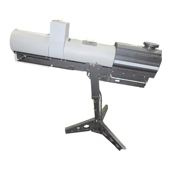
PARTS MANUAL - 11 -... - Page 14 M2 Modular Followspots 1290 XLT Figure 1. 1290 XLT Followspot - 12 -...
- Page 15 M2 Series M2 Modular Followspots 1290 XLT INDEX PART NUMBER DESCRIPTION NUMBER Figure 1 1290 Model 1290 XLT Followspot - 13 -...
- Page 16 M2 Modular Followspots 1290 XLT Figure 2. XLT 2K Xenon Long Throw - 14 -...
- Page 17 M2 Modular Followspots 1290 XLT INDEX PART NUMBER DESCRIPTION QUANTITY NUMBER Figure 2 1290 XLT 2K Xenon Long Throw 129026X Front Lens Assembly (See Figure 3 for Detail) 12905A Front Partition 129092 Bale 129033 Belly Pan Assembly/Blower (See Fig. 7 for Detail)
- Page 18 1290 XLT Figure 3. Front Lens Assembly - 16 -...
- Page 19 M2 Modular Followspots 1290 XLT INDEX PART NUMBER DESCRIPTION QUANTITY NUMBER Figure 3 129026X Front Lens Assembly 1290108 Front Follow Rod 129077 Trolley Weldment 35020D Follow Handle, Drilled, with Set Screw Grommet, Blue Bearing, 1/2 inch 442D Collar, Brake, Drilled, 1/2 inch...
- Page 20 1290 XLT DETAIL Color Changer Figure 4. Color Boom And Color Changer Assemblies - 18 -...
- Page 21 M2 Modular Followspots 1290 XLT INDEX PART NUMBER DESCRIPTION QUANTITY NUMBER Figure 4 129038X Color Boom Assembly 1290385X Color Box Assembly 1290381X Color Changer Assembly (See Figure 5 For Breakdown) 1278110X Color Frame, 9", with Channel 1278110 Color Frame, 9", Ring Only W10SL Washer, Split, Lock, No.
- Page 22 1290 XLT Figure 5. Shutter Assembly - 20 -...
- Page 23 M2 Modular Followspots 1290 XLT INDEX PART NUMBER DESCRIPTION QUANTITY NUMBER Figure 5 Shutter Assembly 127553 Shutter Plate Weldment Rod, Control, 3 Inch N632LOCK Nut, #6-32, Nylon Stop Nut 120641 Iris Assembly 4232 Gobo Slot 4231 Fader Shaft Support - 21 -...
- Page 24 1290 XLT Figure 6. Rear Lens Assembly - 22 -...
- Page 25 M2 Modular Followspots 1290 XLT INDEX PART NUMBER DESCRIPTION QUANTITY NUMBER Figure 6 129027X Rear Lens Assembly 120633 Small Lens 120666 Small Lens Back 1275100 Rear Lens Slide Weldment 127573 Rear Lens Holder 127574 Rear Lens Support 127576 Donut 127823 Spring, trombone 1/2"...
- Page 26 1290 XLT Figure 7. Belly Pan Assembly - 24 -...
- Page 27 M2 Modular Followspots 1290 XLT INDEX PART NUMBER DESCRIPTION QUANTITY NUMBER Figure 7 129033X Belly Pan Assembly 120638 Fan Guard, 4.5 inch 120715 100 CFM Axial Fan 129015X Front Blower Assembly 129033 Belly Pan S10-32X1/2F Screw, Hex, Washer Head, No. 10-32 x 1/2 inch long S10-32X3/8P Screw, Phillips, Pan Head, No.
- Page 28 1290 XLT Figure 8. Focus Assembly - 26 -...
- Page 29 M2 Modular Followspots 1290 XLT INDEX PART NUMBER DESCRIPTION QUANTITY NUMBER Figure 8 129025X Focus Assembly 35022X Knob, 2-1/2" with Set Screw W3/8 Washer, Flat, 3/8", Regular Series 81279-38-A Spacer, 3/4" O.D. x 3/8" I.D. x 1/4" Long, Aluminum 129107 Rod, Focus, 10-3/4"...
- Page 30 1290 XLT Figure 9. Fader Mid Plate Assembly - 28 -...
- Page 31 M2 Modular Followspots 1290 XLT INDEX PART NUMBER DESCRIPTION QUANTITY NUMBER Figure 9 129051X Fader Mid Plate Assembly 1290107 Effects "Z" Bracket Pair with Hardware 1290116 Lower Fader Shutter Blade 1290117 Upper Fader Shutter Blade 1290120 6-19/32" Long 10-32 Rod...
- Page 32 1290 XLT Figure 10. Rear Lamp Adjustment Assembly - 30 -...
- Page 33 M2 Modular Followspots 1290 XLT INDEX PART NUMBER DESCRIPTION QUANTITY NUMBER Figure 10 129031X Rear Lamp Adjustment Assembly 1290100 Inner Rear Lamp Support 1290101 Outer Rear Lamp Support 1290102 Rear Lamp Bearing Support 1290103X Rear Lamp Insulator Assembly 1290122 Spring, 2"...
- Page 34 1290 XLT Figure 11. Fader Shaft Assembly - 32 -...
- Page 35 M2 Modular Followspots 1290 XLT INDEX PART NUMBER DESCRIPTION QUANTITY NUMBER Figure 11 1290379 Fader Shaft Assembly 1290379W Fader Shaft Weldment 251S Collar, 1/2" 251R Collar, 1/2", Reamed Control rod, 4-1/4" x 1/4-20 8LC-045H-01S Spring, Fader Brake N1/4-20 Nut, 1/4-20, Hex, Steel S1/4-20X5/8S Screw, 1/4-20 x 5/8"...
- Page 36 1290 XLT Figure 12. Pulley Wheel Assembly - 34 -...
- Page 37 M2 Modular Followspots 1290 XLT INDEX PART NUMBER DESCRIPTION QUANTITY NUMBER Figure 12 1290380 Pulley Wheel Assembly 129079 Pulley Bracket 81220-25-A Spacer, 1/4" ID x 7/16" Long x 1/2" OD, Aluminum 8A-138 Pulley B1/4-20X114 Bolt, 1/4-20 x 1-1/4" Long, Hex, Steel...
- Page 38 1290 XLT Figure 13. Front Lamp Holder Assembly - 36 -...
- Page 39 M2 Modular Followspots 1290 XLT INDEX PART NUMBER DESCRIPTION QUANTITY NUMBER Figure 13 129123X Front Lamp Holder Assembly 126664 Spring 129040X Front Lamp Contact Assembly 129123 Front Lamp Bale 129123A Front Lamp Bale Bracket 129124 Spring, Lamp Contact 81194-12-S-12 Spacer, 3/8" OD x 1/4" ID x 3/4" Long B1/4-20X114 Bolt, 1/4-20 x 1-1/4"...
- Page 40 1290 XLT Figure 14. Air Flow Switch Assembly - 38 -...
- Page 41 M2 Modular Followspots 1290 XLT INDEX PART NUMBER DESCRIPTION QUANTITY NUMBER Figure 14 441X Air Flow Switch Assembly Pressure Switch Mount 81128-6-A Spacer, #6 x 1/2" Long, Aluminum 89-45 Switch, Air Pressure S6-32X1PP Screw, #6-32 x 1" Long, Phillips, Pan Head Tube, UV Resistant, 3/16"...
- Page 42 1290 XLT Figure 15. 2K Power Tray Assembly - 40 -...
- Page 43 M2 Modular Followspots 1290 XLT INDEX PART NUMBER DESCRIPTION QUANTITY NUMBER Figure 15 129028X 2K Power Tray Assembly Contact Lycian Stage Lighting for information - 41 -...
- Page 44 1290 XLT Figure 16. Yoke Assembly - 42 -...
- Page 45 M2 Modular Followspots 1290 XLT INDEX PART NUMBER DESCRIPTION QUANTITY NUMBER Figure 16 13228X Yoke Assembly 120628 Knob, 2-1/2", 5 Point, M-3/8 132213X Brake and Handle Assembly 132232 Rotation Stop Disk, 7 Gauge, Large 132233 Yoke Pole With Collar 13224...
- Page 46 1290 XLT Figure 17. Base Stem Folding Assembly - 44 -...
- Page 47 M2 Modular Followspots 1290 XLT INDEX PART NUMBER DESCRIPTION QUANTITY NUMBER Figure 17 13227FX Base Stem Folding Assembly 13227FX Base Stem Folding Assembly 13229 Pin, Quick Release "Tee" Handle, 3/8", Gold Fastpin, 3.3" - 45 -...
-
Page 48: 1290 Head Wiring Diagram
FRONT LAMPHOLDER WIRE 129015X FRONT ASSEMBLY LAMPHOLDER IRIS ASSEMBLY 120715 PRESSURE 129123X 115CFM 50CFM SWITCH BLOWER ASSEMBLY LAMP 441X 129037X LAMP 134CFM - GND 240V + IN 932 IGNITER WIRE HARNESS 129035X H Black Large Blower N White (403) G Green WIRE HARNESS 129034X Iris (120715)
Need help?
Do you have a question about the 1290 XLT and is the answer not in the manual?
Questions and answers