
Related Manuals for Voyager DP-263-S

Summary of Contents for Voyager DP-263-S
- Page 1 GSM Door Phone System System Installation, Setting and Operation Manual User Manual (263-S– V1) Please read this user manual completely before operating this system and keep it in a safe place for future reference.
-
Page 2: Table Of Contents
TABLE OF CONTENTS TABLE OF CONTENTS ……………………………………………….………………. IMPORTANT SAFETY INSTRUCTIONS…………………………………………….. UNPACKING YOUR SYSTEM…………………..…………………………………….. SYSTEM DIAGRAMS Front View ……………………………………………………………….…………. Back View ………………………………………………………………….………. Wall Mounting Bracket ……………………………………………………………. INSTALLATION GSM Door Phone…………………………………………………………………… Wiring Diagram & Wiring Instructions …………………………………………..OPERATION Power ON/OFF …………………………………………………………………….. Manager Mode and Functions ……………………………………………….…… MANAGER SETTINGS Change Manager Password ………………………………………………………... -
Page 3: Important Safety Instructions
Thank you for purchasing the GSM Door Phone. To ensure that you enjoy the full capacity of this product, please read this user manual before proceeding. Be sure to keep this manual for future reference in case any challenge or question should arise. -
Page 4: Unpacking Your System
UNPACKING YOUR SYSTEM Your GSM Door Phone system will include the followings: 1 x Door phone unit 1 x AC power adapter 1 x GSM antenna 1 x Wall mounting bracket 1 x Wire 4 x screws for mounting bracket 2 x screws for door phone 1 x User manual Optional Accessories... -
Page 5: Front View
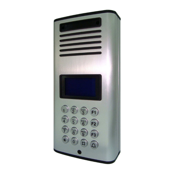
System Diagram (Front View) Acrylic cover Speaker LCD display Keypad 0~9: Number keys F1: Menu/Exit key F2: Delete key F3: ABC/abc/123 exchange button * * * * : Volume & select up # # # # : Volume & select down Microphone Bottom cover... -
Page 6: Back View
System Diagram (Back View) Opening for connecting wall-mount bracket Metal back cover plate Opening for connecting wall-mount latch Wiring terminal SIM card slot GSM Antenna socket USB port GSM antenna Bottom cover... -
Page 7: Wall Mounting Bracket
System Diagram (Wall Mounting Bracket) -
Page 8: Installation
INSTALLATION GSM Door Phone 1. Take the wall-mount bracket from the package and screw it on proper place (as Step 1 & 2 shown below). 2. Open the bottom cover of door unit and pass the wires through the hole. Then, refer to the “Wiring Diagram and Wiring Instruction”... - Page 9 6. Plug the AC adapter into the AC outlet, then the door unit will go into standby mode. WARNING: Only use the original power adapter supplied. Using any other adapter might damage the door unit and cause a risk of electric shock.
-
Page 10: Wiring Diagram & Wiring Instructions
Wiring Instructions 1. System Power Supply Wiring The system power supply (adapter) AC 120V or 230V / DC 13V is provided along with the system (please note whether it can meet local voltage specification). The negative wire is connected to Terminal Pin 1 and the positive wire is connected to Terminal Pin 2. -
Page 11: Operation
OPERATION Before operation: Please make sure the GSM Door Phone is installed correctly. Please also study all button functions before use. Power On/Off Turn the power on Insert the plug of the power adapter into the DC power jack of door unit and the other end into an AC power outlet. -
Page 12: Manager Settings
Manager Settings Under the Manager section, there are 4 main options: “System Setting”, “Volume Setting”, “Door Setting” and “Calling Setting”. System Setting Volume Setting Door Setting Calling Setting Press CALL button to enter System Setting. Change Password Manager Phone # Talking Time Change Manager Password Manager Setting... -
Page 13: Set Minutes For Talk Time
Select Manager Phone # by * * * * /# # # # key and press CALL button. With cursor on the 1, press CALL button to enter phone number Enter phone number with prefix and area code, then press CALL button to save. -
Page 14: Change Speaker Volume
Press * * * * /# # # # UP/DOWN) buttons to adjust volume. Press F1 (EXIT) button to return to the previous option screen and the last setting will be saved automatically. Speaker Volume Change Speaker Volume Manager Setting GSM Setting Speaker Volume <-****..…... -
Page 15: Change Door Opening Password
Under the Manager Menu option, press CALL button. Select Door Setting and press CALL button. Select Open by Password and press CALL button. Press CALL button to toggle between “Enabled” and “Disabled”. Press F1 (EXIT) button to return to the previous option screen and the last setting will be saved. -
Page 16: Calling Setting
Select Door Open Time and press CALL button. Enter the number of seconds (from 03 to 99). Press CALL button to save. Press F1 (EXIT) button to return to previous options screen. Calling Setting Set Calling Time Manager Setting Calling Setting Calling Time Calling Time Calling Time... -
Page 17: Subscriber Id Number Setting
Subscriber: The Subscriber function supports to set up multiple tenants and enable the user to press a subscriber number by the CALL button to connect with the tenant. A subscriber ID # can be set from 1 to 6 digits in length. There are maximum 263 subscribers which can have 2 phone numbers programmed for each. -
Page 18: Contacting A Subscriber
Contact a Subscriber Under the "Welcome!" mode, enter User ID number (from 1 ~ 999999) and then press CALL button. If the ID exists, the system will start dialing and show “Calling…” on the screen. When the phone is connected, the screen will show “Talking”. Calling- - - Talking- - - Incorrect! -
Page 19: Sim Card
seconds, the screen will go back to the standby mode – “Welcome!” If a Subscriber ID is entered and no button is pressed within 6 seconds, the screen will go back to the standby mode. If no button is pressed within 30 seconds under the Manager or Subscriber option, the screen will go back to the standby mode.
Need help?
Do you have a question about the DP-263-S and is the answer not in the manual?
Questions and answers