Advertisement
Quick Links
Installation and User Guide
Compatible Equipment
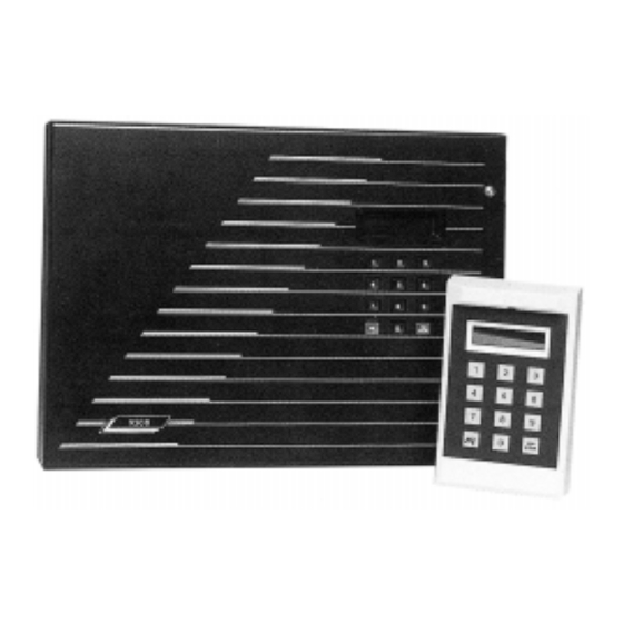
9525
Remote Keypad
9505
LIM
9507
LIM + PSU
9508
Shunt LIM (4 zones)
9509
Shunt LIM Controller
9510
EOL LIM (3 Zones)
9585
Engineers Printer (Centronics)
9589
Printer lead (Centronics)
9590
Hardware Mimic System
9597
Computer Mimic System
9500
496332 Issue 1
1 of 22
Advertisement

Summary of Contents for Innovate 9500 series
- Page 1 9500 Installation and User Guide Compatible Equipment 9525 Remote Keypad 9505 9507 LIM + PSU 9508 Shunt LIM (4 zones) 9509 Shunt LIM Controller 9510 EOL LIM (3 Zones) 9585 Engineers Printer (Centronics) 9589 Printer lead (Centronics) 9590 Hardware Mimic System 9597 Computer Mimic System 496332 Issue 1...
- Page 2 9500 Introduction The 9500 Series System is a fully programmable, microprocessor controlled, electronic intruder alarm system designed to meet the security requirements of medium to large industrial and commercial premises. The system operates on the “Multiplex” principle using four main data high- ways (or branches) from the main control panel.
-
Page 3: Technical Specification
9500 Technical Specification of the seven circuit attributes, (Attributes do not apply to P.A., Technical Alarm or 24 hour circuits). The main control panel is provided with outputs suitable for connection to a printer or a completely programmed mimic diagram system. The system will accept a plug-in digital communicator (fast format only) or a direct-line interface, which can also be used to connect the Series 9500 to “Red Care”... - Page 4 9500 Wiring Figure 2. Main PCB Layout Figure 3. Main PCB Connections 4 of 22 496332 Issue 1...
- Page 5 9500 Wiring Figure 4. Standard LIM PCB Figure 5. Connection of Shunt LIM as Single Shunt 496332 Issue 1 5 of 22...
- Page 6 Wiring 9500 Figure 6. Connection of Shunt LIM as Multiple Shunt Figure 7. Connection of End of Line Resistor LIM 6 of 22 496332 Issue 1...
- Page 7 9500 Wiring Figure 8. Remote PSU/LIM Layout and Connections Figure 9. Remote Keypad Connections 496332 Issue 1 7 of 22...
- Page 8 Wiring 9500 Figure 10. Wiring the Remote Keypad(s) to the Branch Loops Figure 11. 9558 Communicator Layout and Connections 8 of 22 496332 Issue 1...
- Page 9 9500 Wiring Figure 12. 9576 Interface Layout Figure 13. 9576-01 Interface Board Layout 496332 Issue 1 9 of 22...
- Page 10 9500 Programming Initial Start Up Check that all LIM box tampers are closed. Make sure that the Bell and Strobe is not connected to the main 9500 PCB. Link out any circuits that are nnot used. When powering up the panel for the first time: Close the control panel lid and connect the mains supply.
- Page 11 9500 Engineering Program Commands Press Yes. You are now in Engineering Mode. Defaults The default Manager 1 Code is 4567 followed by ‘Enter’. The default Engineer Code is 7890 followed by ‘Enter’. All circuits are set to Normal Alarm, and not allocated any specific function. Engineering Program Commands While programming the system, the control unit shows a series of questions on the keypad display.
- Page 12 Engineering Program Commands 9500 12 of 22 496332 Issue 1...
- Page 13 9500 Engineering Program Commands 496332 Issue 1 13 of 22...
- Page 14 Engineering Program Commands 9500 14 of 22 496332 Issue 1...
- Page 15 9500 Leaving Engineering Mode Leaving Engineering Mode Before leaving Engineering Mode, check that the Bell, Strobe, all detectors, tampers etc., are connected. Also check that the 6.Ah standby battery is connected and all lids are closed on LIMs, keypads and main control panel. If your system is fitted with remote signalling, check that it is programmed for ‘Engineer Reset’, and proceed as follows: The display shows:...
- Page 16 Re-entering Engineering Mode 9500 Followed by: Branch 4 No of LIMs=6 Followed by: Total LIMs=26 confirm: yes/no EITHER Press No The display shows: Review system configuration Check for system wiring faults, LIM failures etc. See "Branch Configuration" OR Press Yes The display shows: Please wait...
-
Page 17: Log Events
9500 Refreshing the System prevent any problems of high current being drawn which could damage the control panel. 2. The Engineer Reset, Test Functions and Reports can be selected without opening the control panel lid. Refreshing The System If the system requires all the programmed information to be deleted and returned to the factory de-faults, it is possible to refresh the system in the following way. - Page 18 9500 Log Events 9500 Aux-pwr-restored AUX DC Power power restored Entry by keypad Entry initiated at panel keypad CUST WALK TEST ENG WALK TEST Changed location Site location code changed Online print off Fault direct line Direct line fault input tripped Set proc aborted Setting procedure terminated Snd/bll/strb tst...
- Page 19 9500 9500 Log Events WT tamper #### Walk test (engineer walk test only, printer only) WT PA cct #### Walk test (engineer walk test only, printer only) WT PA tamp #### Walk test (engineer walk test only, printer only) WT FE cct #### Walk test (engineer walk test only, printer only) WT FE tamp #### Walk test (engineer walk test only, printer only)
- Page 20 9500 Log Events 9500 -LkSt tamper #### Violation of lock set tamper #### Entry by FE #### Entry via final exit door #### Entry by RKP #### Entry at RKP DKnock cct -#### Violation of double knock circuit #### (not an alarm event) Tamper RKP #### Violation of rkp ### back tamper, or excess...
-
Page 21: User Commands
9500 User Commands LIM ### shunted Restore branch The following are software diagnostic messages which should appear in the log very rarely. They all indicate that a fault has occurred, which has caused the microprocessor to reset. The system will operate correctly following this reset. - Page 22 Cleaner Code Operation 9500 Cleaner Code Operation The Cleaner Code can ONLY arm the system. If when using this code to arm the system and a fault occurs on exit, then the cleaner can return the system to DAY status. However, if the system has set then this code will NOT disarm the system.
Need help?
Do you have a question about the 9500 series and is the answer not in the manual?
Questions and answers