Table of Contents
Advertisement
Advertisement
Table of Contents

Related Manuals for Bravo EVT-168

Summary of Contents for Bravo EVT-168
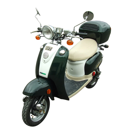
- Page 1 SERVICE MANUAL SERVICE MANUAL EVT-168 EVT-168...
-
Page 2: Table Of Contents
Table of Contents 23. Rear Shock Absorber 1. Front Cover 2. Seat 24. Rear Caliper 3. Center Cover 25. Brake Master Cylinder 4. Left Side Cover 26. Brake Hose 5. Right Side Cover 27. Brake Fluid 6. Footrest Board 28. Brake Pad 7. -
Page 3: Front Cover
Front Cover Tools Required: Phillips screwdriver Time: Allow 10 minutes for procedure 1. Release the screw on the front cover. 2. Release four screws on the back of the front cover. 3. Remove the front cover. 4. Follow with the reversed steps to restore. -
Page 4: Seat
Seat Tools Required: T-bend socket wrench, 10mm Time: Allow 10 minutes for procedure 1. Release two nuts on the seat. 2. Remove the seat. 3. Follow with the reversed steps to restore. -
Page 5: Center Cover
Center Cover Tools Required: T-bend socket wrench, 8mm Time: Allow 10 minutes for procedure 1. Release the screw on the center cover. 2. Remove the center cover. 3. Follow with the reversed steps to restore. -
Page 6: Left Side Cover
Left Side Cover Tools Required: Phillips screwdriver Time: Allow 10 minutes for procedure 1. Remove the center cover. 2. Release four screws on the left side cover. 3. Remove the left side cover. 4. Follow with the reversed steps to restore. -
Page 7: Right Side Cover
Right Side Cover Tools Required: Phillips screwdriver Time: Allow 10 minutes for procedure 1. Release the screw on the cover. 2. Remove the cover. 3. Release four screws on the right side cover. 4. Remove the right side cover. -
Page 8: Footrest Board
Footrest Board Tools Required: T-bend socket wrench, 10mm Time: Allow 10 minutes for procedure 1. Release four screws on the footrest board. 2. Remove the footrest board. 3. Follow with the reversed steps to restore. -
Page 9: Tail Bracket
Tail Bracket Tools Required: Y-bend socket wrench, 10mm; hex-key wrench, 6mm Time: Allow 10 minutes for procedure 1. Release the screw on the tail bracket. 2. Release two nuts on the tail bracket. 3. Remove the tail bracket. 4. Follow with the reversed steps to restore. -
Page 10: Rear Body Cover
Rear Body Cover Tools Required: Phillips screwdriver Time: Allow 10 minutes for procedure 1. Release four screws on the rear cover. 2. Remove the plastic cover on the seat lock. 3. Release the 6-pin connector and 2-pin connectors. 4. Remove the rear cover. 5. -
Page 11: Lower Cover
Lower Cover Tools Required: Phillips screwdriver Time: Allow 10 minutes for procedure 1. Remove the footrest board and release the screw on the front of the lower cover. 2. Remove the lower cover. 3. Follow with the reversed steps to restore. -
Page 12: Fairing
Fairing Tools Required: T-bend socket wrench, 8mm Time: Allow 10 minutes for procedure 1. Remove the footrest board and the hanger on the back of the fairing. 2. Remove the fairing. 3. Follow with the reversed steps to restore. -
Page 13: Front Fender
Front Fender Tools Required: Phillips screwdriver Time: Allow 10 minutes for procedure 1. Release three screws on the rear front fender. 2. Release the screw on the top of the rear front fender and remove. 3. Follow with the reversed steps to restore. -
Page 14: Rear Fender
Rear Fender Tools Required: Phillips screwdriver Time: Allow 10 minutes for procedure 1. Remove the right and left side covers and release two screws on the rear fender. 2. Remove the rear fender. 3. Follow with the reversed steps to restore. -
Page 15: Head Lamp Bulb
Head Lamp Bulb Tools Required: Phillips screwdriver Time: Allow 10 minutes for procedure 1. Release the screw on the head lamp ring. 2. Release the head lamp ring. 3. Release the spring on the bulb base. 4. Remove the bulb base and replace the bulb. 5. -
Page 16: Front Direction Lamp Bulb
Front Direction Lamp Bulb Tools Required: Phillips screwdriver Time: Allow 10 minutes for procedure 1. Release the screw on the base of the direction lamp. 2. Release the screw on the cover of the bulb. ease the screw on the cover of the bul 3. -
Page 17: Tail Lamp Bulb
Tail Lamp Bulb Tools Required: Phillips screwdriver Time: Allow 10 minutes for procedure 1. Release two screws on the tail lamp cover and remove. 2. Replace the light bulb. 3. Follow the reversed steps to restore. -
Page 18: Rear Direction Lamp Bulb
Rear Direction Lamp Bulb Tools Required: Phillips screwdriver Time: Allow 10 minutes for procedure 1. Release the screw on the base of the direction lamp. 2. Remove the cover of the direction lamp. 3. Replace the bulb and follow the reversed steps to restore. -
Page 19: Main Switch
Main Switch Tools Required: T-bend socket wrench, 10mm Time: Allow 10 minutes for procedure 1. Remove front covers. 2. Release the 4-pin connector. 3. Release two screws on the main switch and remove the key switch. 4. Follow with the reversed steps to restore. -
Page 20: Seat Lock Assembly
Seat Lock Assembly Tools Required: Phillips screwdriver Time: Allow 10 minutes for procedure 1. Remove the rear body cover. 2. Remove the seat box rim. 3. Release two screws on the seat lock. 4. Release two screws on the seat lock switch. 5. -
Page 21: Horn
Horn Tools Required: Open-end wrench, 10mm Time: Allow 10 minutes for procedure 1. Remove the front cover. 2. Release two connectors on the horn. 3. Release the screw on the horn. 4. Follow with the reversed steps to restore. -
Page 22: Flasher Relay
Flasher Relay Time: Allow 10 minutes for procedure 1. Remove the front cover. 2. Release the 2-pin connector on the flasher relay. 3. Follow with the reversed steps to restore. -
Page 23: Dc To Dc Converter
DC to DC Converter Tools Required: Phillips screwdriver Time: Allow 10 minutes for procedure 1. Remove the side covers and footrest board. 2. Release the 4-pin connector for the converter. 3. Release three screws on the converter. 4. Follow with the reversed steps to restore. -
Page 24: Controller
Controller Tools Required: Phillips screwdriver Time: Allow 10 minutes for procedure 1. Remove the right side cover. 2. Release connectors of controller wire harness. 3. Release the copper nut throttle cable and remove (replace with nail to prevent pillar drawing back). 4. -
Page 25: Rear Shock Absorber
Rear Shock Absorber Tools Required: T-bend socket wrench, 10mm Time: Allow 10 minutes for procedure 1. Remove the rear body cover. 2. Release two screws on the rear shock absorber. 3. Follow with the reversed steps to restore. -
Page 26: Rear Caliper
Rear Caliper Tools Required: Box wrench; Y-bend socket wrench, 12mm Time: Allow 10 minutes for procedure 1. Release the screw on the rear caliper. Avoid leaking fuel onto the pad. 2. Release the screw on the pad. 3. Release two mounting screws on the caliper. 4. -
Page 27: Brake Master Cylinder
Brake Master Cylinder Tools Required: Box wrench, 12mm; hex-key wrench, 5mm Time: Allow 10 minutes for procedure 1. Check the fluid in reservoir for refuel or replace the brake fluid. 2. Replace reservoir if leakage occurs, or if gasket fails or wears out. 3. -
Page 28: Brake Hose
Brake Hose Tools Required: Box wrench; diagonal cutting pliers Time: Allow 10 minutes for procedure 1. Remove all the covers and fenders. 2. Release the screw on the brake hose of the rear caliper. Avoid leaking fuel onto the pad. 3. -
Page 29: Brake Fluid
Brake Fluid Tools Required: Phillips screwdriver Time: Allow 10 minutes for procedure 1. Release two screws on the cover of the master cylinder. 2. Place tube and fluid vacuum on the rear caliper’s screw. 3. Pour brake fluid into the master cylinder. 4. -
Page 30: Brake Pad
Brake Pad Tools Required: Y-bend socket wrench, 12mm Time: Allow 10 minutes for procedure 1. Release the screw on the rear caliper. 2. Remove the rear caliper. 3. Remove the brake pad from the base of the caliper. 4. Follow with the reversed steps to restore. -
Page 31: Direct Driven Hub-Motor
Direct Driven Hub-Motor Tools Required: Phillips screwdriver; open end wrench, 24mm Time: Allow 10 minutes for procedure 1. Release three screws on the motor cord cover. 2. Cut off the band. 3. Release the black connector of the motor cord. 4. -
Page 32: Brake Disk
Brake Disk Tools Required: Hex-key wrench, 6mm Time: Allow 10 minutes for procedure 1. Remove the motor from the frame. 2. Release three screws on the brake disk. 3. Remove the brake disk. 4. Follow with the reversed steps to restore. -
Page 33: Rear Fork
Rear Fork Tools Required: Box wrench, 17mm Time: Allow 10 minutes for procedure 1. Remove the rear caliper, rear motor, and rear shock absorber. 2. Cut off the band on the brake hose and release the screw on the rear fork. 3. -
Page 34: Front Shock Absorber
Front Shock Absorber Tools Required: Phillips screwdriver; Y-bend socket wrench, 12mm Time: Allow 10 minutes for procedure 1. Remove the front fender. 2. Release the screw on the front fork cover and remove. 3. Release two screws on the front shock absorber and remove. 4. -
Page 35: Head Lamp
Head Lamp Tools Required: Box wrench, 14mm Time: Allow 10 minutes for procedure 1. Remove the front cover. 2. Release the 6-pin connector. 3. Release the screw on the head lamp holder. 4. Follow with the reversed steps to restore. -
Page 36: Front Direction Lamp
Front Direction Lamp Tools Required: Phillips screwdriver Time: Allow 10 minutes for procedure 1. Remove the front cover. 2. Release the 2-pin connector on the front direction lamp (Green, left; red, right). 3. Release the screw on the handle switch and remove the direction lamp. 4. -
Page 37: Current Meter And Speedometer
Current Meter and Speedometer Tools Required: T-bend socket wrench, 8mm Time: Allow 10 minutes for procedure 1. Remove the front cover. 2. Release the 6-pin connector and the 2-pin connector on the meters. 3. Release two screws on the instrument panel. 4. -
Page 38: Left Handle Switch
Left Handle Switch Tools Required: Phillips screwdriver Time: Allow 10 minutes for procedure 1. Remove the front cover. 2. Release all connectors for the left handle switch. 3. Release two screws on the left handle switch. 4. Follow with the reversed steps to restore. -
Page 39: Right Handle Switch
Right Handle Switch Tools Required: Phillips screwdriver Time: Allow 10 minutes for procedure 1. Remove the front cover. 2. Release all connectors for the right handle switch. 3. Release two screws on the right handle switch. 4. Follow with the reversed steps to restore. -
Page 40: Tail Lamp Assembly
Tail Lamp Assembly Tools Required: Open-end wrench, 10mm Time: Allow 10 minutes for procedure 1. Remove the rear fender. 2. Release the three screws on the base of the tail lamp assembly. 3. Release all connectors for the tail lamp assembly. 4. -
Page 41: Front Brake Cable
Front Brake Cable Time: Allow 10 minutes for procedure 1. Remove the front cover. 2. Release the adjusting bolt on the brake cable and pull out the brake cable 3. Remove the brake cable from the brake cable head. 4. Follow with the reversed steps to restore. -
Page 42: Throttle Cable
Throttle Cable Tools Required: Phillips screwdriver Time: Allow 10 minutes for procedure 1. Follow page 22 ( step 1 to step 3) to pull the throttle pillar out. 2. Follow page 37 ( step 1 to step 3) to remove the handle switch. 3. -
Page 43: Handle
Handle Tools Required: hex-key wrench (5mm) Time: Allow 10 minutes for procedure 1. Remove the instrument panel, handle switches (right and left) and brake master cylinder. 2. Release four screws on the handle Clamp. 3. Remove the handle. 4. Follow with the reversed steps to restore. -
Page 44: Steering Bracket
Steering Bracket Tools Required: Phillips screwdriver, box wrench (14mm) Time: Allow 10 minutes for procedure 1. Remove handle. 2. Release the screw on the steering bracket cover. 3. Remove the steering bracket cover. 4. Release the screw on the steering bracket. 5. -
Page 45: Front Fork And Ball Race
Front Fork and Ball Race Tools Required: open-end wrench (32mm, 45mm) Time: Allow 10 minutes for procedure 1. Remove front covers, instrument panel, head lamp, handle and steering bracket. 2. Remove front wheel. 3. Release the nut on the ball race and check the steel balls to see if they are missing. 4. -
Page 46: Part Summary
Part Summary FIG.01 FRONT WHEEL Item NO. Part NO. Description Qty. 0268-01003501 RIM, FRONT 0268-01005500 FRONT WHEEL ASSEMBLY 6277-100105 DRUM BRAKE COMP., FRONT 0168-01001300 SHAFT, FRONT FORK 6278-100205 COVER, SHAFT 0268-0100550A DUST COVER (LARGE) 0268-0100550B DUST COVER (SMALL) 0268-01006500 COVER, METER GEAR 0268-01002900 SCREW, SHAFT 0268-01003700... - Page 47 Part Summary (cont’d) FIG.02 FORK Item NO. Part NO. Description Qty. 0268-01003601 FRONT FORK 0168-01001300 SWING ARM SET, LEFT & RIGHT 0268-010046A1 SHOCK ABSORBER, FRONT 6112-080358 SCREW, HEX./FLANGE 6141-080758 NUT, HEX./FLANGE 0268-01003400 RACE, BALL SET 0268-30201 CHROME COVER, L. CUSHION 6127-061511 SCREW, PAN/+...
- Page 48 Part Summary (cont’d) FIG.03 REAR WHEEL Item NO. Part NO. Description Qty. 02A9-05000101 MOTOR ASSY. 0241-20201 BRAKE DISC, REAR 6240-00001 TIRE, TUBELESS 6109-080201 SCREW, BRAKE DISC 0241-10601 TIRE VALVE 6248-00001 CONNECTOR, BLACK 0268-01005901 REAR FORK SET 6113-103001 BOLT (M10*300) 6143-100801 NUT, DOME (M10 *8) 6150-1030305 PLAIN WASHER...
- Page 49 Part Summary (cont’d) FIG.04 FRAME Item NO. Part NO. Description Qty. 0268-01001100 FRAME 6266-100104 MAIN STAND 6111-081255 BOLT (M8*125) 6142-080855 NUT, FLANGE (M8) 0268-50301 SPRING, MAIN STAND 6266-200103 SIDE STAND 0268-05002200 LOCK SET 6112-060146 SCREW, HEX. FLANGE (M6*14) 0268-01004702 TAIL BRACKET 6100-080201 SCREW, SOCKET (M8*20) 6144-060601...
- Page 50 Part Summary (cont’d) FIG.05 CONTROLLER Item NO. Part NO. Description Qty. 0268-05002802 CONTROLLER (DOT) 6126-052005 SCREW, PAN HEAD (M5*20) 6255-00001 HORN 6112-060126 SCREW, HEX. FLANGE (M6*12) 0268-05003000 FLASHER RELAY(DOT) 0268-05002300 DC/DC CONVERTER (DOT) 0268-05000101 MAIN CONTROL CORD (DOT) 6256-00200 TIE BAND, Medium 6256-00280 TIE BAND, Long 6126-051031...
- Page 51 Part Summary (cont’d) FIG.06 HANDLE BAR Item NO. Part NO. Description Qty. 0268-42301 STEERING BRACKET 6111-100407 SCREW, HEX./FLANGE 6141-100908 NUT, HEX./FLANGE 0268-42401 CHROME COVER, STRG. BRACKET 0268-01001600 LOWER HANDLE CLAMP 0268-40101 HANDLE 0268-01001700 UPPER HANDLE CLAMP, LEFT 0268-01001800 UPPER HANDLE CLAMP, RIGHT 0268-05001900 HANDLE SWITCH, LEFT 0268-05002001...
- Page 52 Part Summary (cont’d) FIG.07 METER/HEAD LIGHT Item NO. Part NO. Description Qty. 0268-42601 BRACKET, METER ASSY. 0268-425011 BRACKET, HEADLIGHT 6141-060608 NUT, HEX./FLANGE 0268-05003100 HEADLIGHT COMP. (DOT) 6113-080406 SCREW, HEX./FLANGE 6141-080756 NUT, HEX./FLANGE 0268-050025A1 CURRENT METER 0268-05002601 SPEEDOMETER (DOT) 0268-01004100 COPPER COVER 0268-04000400 RUBBER COVER 0268-014000211...
- Page 53 Part Summary (cont’d) FIG.08 TAIL LAMP Item NO. Part NO. Description Qty. 6263-210102 TAIL LAMP COVER 6263-21101 TAIL LAMP 6276-200161 PLATE, LICENCE PLATE 0268-05003300 DIRECTIONAL LAMP, REAR (L) (DOT) 0268-05003301 DIRECTIONAL LAMP, REAR (R) (DOT) 0268-71104 MOUNTING PLATE, TAIL LAMP 0268-71701 REAR FENDER 6246-10002...
- Page 54 Part Summary (cont’d) FIG.09 SEAT Item NO. Part NO. Description Qty. 0268-70101 SEATBOX RIM 0268-01004900 SEAT HINGE 6112-060126 SCREW, HEX./FLANGE 0268-24000200 SEAT 0268-01004910 PIN, SEAT 0268-72301 BRACKET, SEAT 6141-060608 NUT, HEX./FLANGE...
- Page 55 Part Summary (cont’d) FIG.10 FRONT COVER Item NO. Part NO. Description Qty. 0268-13003001 FAIRING (LIGHT BLUE) 0268-13003002 FAIRING (LIGHT ORANGE) 0268-13003003 FAIRING (DARK GREEN) 0268-13003004 FAIRING (PURPLE RED) 0268-70891 R. PLUG, FAIRING 0268-70892 L. PLUG CAP, FAIRING 0268-70893 HANGER, SIDE 6127-061511 SCREW, PAN/+ 6269-210161...
- Page 56 Part Summary (cont’d) FIG.11 SIDE COVER Item NO. Part NO. Description Qty. 0268-70501 LEFT COVER (LIGHT BLUE) 0268-70508 LEFT COVER (LIGHT ORANGE) 0268-70505 LEFT COVER (DARK GREEN) 0268-70504 LEFT COVER (PURPLE RED) 0268-70601 RIGHT COVER (LIGHT BLUE) 0268-70608 RIGHT COVER (LIGHT ORANGE) 0268-70605 RIGHT COVER (DARK GREEN) 0268-70604...
- Page 57 Part Summary (cont’d) FIG.12 FOOTREST BOARD Item NO. Part NO. Description Qty. 0268-71303 FOOTREST BOARD, LIGHT BROWN 6112-060126 SCREW, HEX./FLANGE 0268-71401 FRONT BODY COVER, WHITE 0268-13001309 FRONT BODY COVER, SILVER 0268-70102 COVER, LOWER 6127-061511 SCREW, HEX./FLANGE 6113-0603561 SCREW, HEX./FLANGE 6150-0613105 WASHER 0268-24000101 REFLECTOR(RED) (DOT)
- Page 58 Part Summary (cont’d) FIG.13 BATTERY Item NO. Part NO. Description Qty. 181-460-10 BATTERY, LEV 12500 6261-040621 BATTERY CORD SET, LONG 6261-050621 BATTERY CORD SET, SHORT 0299-05000400 CONNECTION CABLE, BATTERY 6243-100119 CHARGER...
- Page 59 STORAGE CASE, LIGHT ORANGE 0268-24000303 STORAGE CASE, DARK GREEN 0268-24000304 STORAGE CASE, PURPLE RED 0268-24000309 STORAGE CASE, SILVER 0268-01004702 EVT-168 CARGO CASE BRACKET 0268-13000408 FRONT FENDER, CHROME 0241-80901 FRONT BASKET 0241-305211 BRAKE PAD, BLUE (UNCUT) 0268-41002 BRAKE CABLE, FRONT (1206MM)
Need help?
Do you have a question about the EVT-168 and is the answer not in the manual?
Questions and answers