Table of Contents
Advertisement
Quick Links
Advertisement
Table of Contents

Summary of Contents for Furumo NAVpilot-711C
- Page 1 OPERATOR'S MANUAL AUTO PILOT NAVpilot-711C Model www.furuno.com...
- Page 2 (Elemental Chlorine Free) The paper used in this manual is elemental chlorine free. FURUNO Authorized Distributor/Dealer 9-52, Ashihara-cho, Nishinomiya, 662-8580, JAPAN A: OCT. 2013 Printed in Japan All rights reserved. A1: NOV. 14, 2013 Pub. No. OME-72780-A1 (REFU) NAVpilot-711C 00017829010...
-
Page 3: Important Notices
IMPORTANT NOTICES General • This manual has been authored with simplified grammar, to meet the needs of international us- ers. • The operator of this equipment must read and follow the descriptions in this manual. Wrong op- eration or maintenance can cancel the warranty or cause injury. •... - Page 4 SAFETY INSTRUCTIONS Please read these safety instructions before you operate the equipment. Indicates a condition that can cause death or serious injury if WARNING not avoided. Indicates a condition that can cause minor or moderate injury CAUTION if not avoided. Warning, Caution Mandatory Action Prohibitive Action...
- Page 5 SAFETY INSTRUCTIONS WARNING LABEL CAUTION CAUTION A warning label is attached to the processor unit. Do not remove the label. If the label is missing or In case of power failure, turn off the damaged, contact your dealer about replacement. autopilot or manually steer the vessel.
-
Page 6: Table Of Contents
TABLE OF CONTENTS FOREWORD ........................vii SYSTEM CONFIGURATION ..................viii EQUIPMENT LISTS ......................ix OPERATIONAL OVERVIEW .................1-1 1.1 Controls........................1-1 1.2 How to Turn the Power On/Off................... 1-2 1.2.1 How to power the system................1-2 1.2.2 How to power off the system................1-2 1.3 How to Adjust the Brilliance .................. - Page 7 TABLE OF CONTENTS 2.10.4 Tacking in WIND mode (WIND TACK) ............2-30 2.11 OVRD mode (for IPS drive) ..................2-34 2.12 Safe Helm Mode.......................2-35 2.13 Power Assist Mode....................2-37 ALARMS ........................3-1 3.1 Alarm Menu ........................3-1 3.2 Alarm Buzzer ......................3-2 3.3 Buzzer Interval......................3-2 3.4 Watch Alarm .......................3-3 3.5 Deviation Alarm ......................3-3 3.6 XTE Alarm ........................3-4 3.7 Arrival Alarm .......................3-4...
- Page 8 TABLE OF CONTENTS 5.5.1 Message pop-up display ................5-12 5.5.2 Message board .................... 5-13 5.5.3 Message description ..................5-13 5.6 Sensor in Use Display....................5-16 INSTALLATION AND WIRING ................6-1 6.1 Installation ........................6-1 6.1.1 Installation location..................6-1 6.1.2 When FAP-7011 is replaced with FAP-7011C ..........6-2 6.1.3 How to install the control unit .................
-
Page 9: Foreword
FOREWORD A Word to the Owner of the NAVpilot-711C Congratulations on your choice of the NAVpilot-711C. We are confident you will see why the FU- RUNO name has become synonymous with quality and reliability. Since 1948, FURUNO Electric Company has enjoyed an enviable reputation for innovative and dependable marine electronics equipment. -
Page 10: System Configuration
SYSTEM CONFIGURATION Control Unit FAP-7011C Control Unit FAP-7001 Control Unit Qty: Max. 6* The processor unit has two connection : Standard lines for the control unit. : Option Three control units can be connected : User Supply per each connection line. Contact Signal IN Solenoid Valve... -
Page 11: Equipment Lists
EQUIPMENT LISTS Standard supply Name Type Code No. Remarks FAP-7011C Control Unit FAP-7002 Processor Unit FAP-6112-200 Rudder Refer- May or may not be supplied ence Unit depending on order. Installation CP64-03101 001-082-720 For processor unit Materials CP64-02601 009-001-170 For rudder reference unit May or may not be supplied depending on order. - Page 12 EQUIPMENT LISTS Name Type Code No. Remarks MJ-A10SPF0001-060+ 001-081-150-10 Cable Assy. For distributor, 6 m MJ-A10SPF0001-120+ 001-081-160-10 For distributor, 12 m BD-07AFFM-LR-100 001-081-170-10 For control unit, 10 m, connector at one end BD-07AFFM-LR-150 001-081-180-10 For control unit, 15 m, connector at one end BD-07AFFM-LR-200 001-081-190-10 For control unit, 20 m,...
-
Page 13: Operational Overview
OPERATIONAL OVERVIEW Controls NAV key (MENU) key Select the NAV mode. Momentary press: Open the turn menu. Long press: Open/close the menu. (PORT) key (STBD) key Steer boat to port. Steer boat to starboard. (POWER/STBY) key AUTO key Momentary press: Select the AUTO mode. -
Page 14: How To Turn The Power On/Off
The startup test checks the ROM, RAM and backup of the processor unit and control unit. The test also checks for the presence of heading from the heading sensor and rudder angle information from the rudder refer- ence unit. NAVpilot-711C Startup Test Processor 6454007-**.** Controller 6454011-**.**... -
Page 15: How To Adjust The Brilliance
1. OPERATIONAL OVERVIEW How to Adjust the Brilliance Note: If the unit becomes hot, the brilliance is lowered automatically. 1. Long press the key to open the menu. Message Display Color : White Sensor In Use Brilliance Advanced AUTO: ON Net Towing AUTO : OFF 2. -
Page 16: How To Select A Display
1. OPERATIONAL OVERVIEW How to Select a Display There are three displays to select from each steering mode. To select a display, do the following operation according to the steering mode. • STBY mode: Press the • AUTO and WIND mode: Press the AUTO key. •... -
Page 17: Highway Display
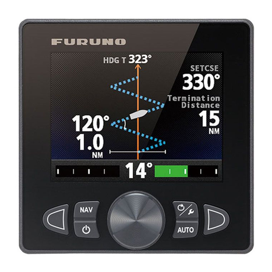
1. OPERATIONAL OVERVIEW Highway display The highway display provides a graphic presentation of your boat’s progress along its intended course. The own ship marker moves according to your boat’s track to the waypoint. Waypoint mark Ship's heading Waypoint name Direction to next waypoint HDG T HDG T (Turn to PORT) -
Page 18: Rudder Display
1. OPERATIONAL OVERVIEW Rudder display The rudder display shows analog and digital rudder angle. Note: Not available with Fantum Feedback Ship's heading Steering mode data HDG T HDG T (See page 1-6.) SETCSE SETCSE Rudder angle/direction P: to “port” Rudder angle S: to “starboard”... -
Page 19: Numerical Display
1. OPERATIONAL OVERVIEW 1.5.2 Numerical display The numerical display provides relevant navigation data according to the steering mode, on three screens. Type-1 Type-2 Type-3 The table below shows the layout and data provided with each steering mode. Steering mode Layout Display data STBY mode Type-1... -
Page 20: How To Select The Display Data
1. OPERATIONAL OVERVIEW 1.5.3 How to select the display data You can select the display data to show in the STBY, AUTO, NAV, and WIND modes. 1. Long press the key to open the menu. 2. Rotate the Course control knob to select [Other Menu] then push the knob. 3. - Page 21 1. OPERATIONAL OVERVIEW 7. Rotate the Course control knob to select display data desired then push the knob. The table below shows all the display data available. Page/Data Data Displayed Data meaning Graphic / numerical data [Normal] Numerical display (see section 1.5.2) Page 1: [Data 1] [Compass] Compass rose...
-
Page 22: How To Select The Display Data With The Key Operation (Stby Mode Only)
1. OPERATIONAL OVERVIEW 1.5.4 How to select the display data with the key operation (STBY mode only) You can select the display data to show in the STBY mode with the key operation. 1. Short press the key to go to the STBY mode. 2. -
Page 23: Steering Modes
STEERING MODES This chapter describes the steering modes and functions of the NAVpilot. STBY Mode After turning on the power, the equipment goes to the STBY mode. This is a manual steering mode. When sailing into or out of a harbor, steer the vessel in the STBY mode by using the steering wheel (helm) of your boat. -
Page 24: How To Get The Auto Mode
2. STEERING MODES 2.2.1 How to get the AUTO mode To get the AUTO mode, do as follows: 1. Direct the boat toward required course. 2. Press the AUTO key to activate the AUTO mode. Your boat automatically maintains the current course when the AUTO key is pressed. -
Page 25: Advanced Auto Mode
2. STEERING MODES 2.2.2 Advanced AUTO mode The AUTO mode keeps a set course, but your boat’s course can change by the effects of tide and wind. To adjust for the effects of tide and wind, use the Advanced AUTO mode. -
Page 26: Nav Mode
2. STEERING MODES NAV Mode NAVpilot steers the vessel towards the current waypoint while compensating for the effects of tide and wind. When connected to a GPS navigator, NAVpilot steers the vessel to follow a series of waypoints in sequence. When you arrive at each waypoint or destination, audible and visual alerts are activated. -
Page 27: How To Get The Nav Mode
2. STEERING MODES 2.3.1 How to get the NAV mode To get the NAV mode, do as follows: 1. Set the destination waypoint (or route) on the GPS navigator or chartplotter. To navigate a route, make sure that your plotter is navigating towards the nearest or required waypoint before you put the NAVpilot into the NAV mode. -
Page 28: Sailing Method For The Nav Mode
2. STEERING MODES 2.3.2 Sailing method for the NAV mode Your vessel can go off course between waypoints in the NAV mode. This can occur when, for example, a command is received from a remote controller. To return to the course set, three methods are available: [Course], [XTE (Precision)], and [XTE (Econ- omy)]. -
Page 29: Waypoint Switching Method
2. STEERING MODES 2.3.3 Waypoint switching method When you arrive at a waypoint on a route in the NAV mode, you can switch to the next waypoint automatically or manually. Select waypoint switching method as follows: 1. In the NAV mode, long press the key to show the menu. -
Page 30: How To Set The Steering Behavior Of Your Boat After You Arrive To A Waypoint
2. STEERING MODES 2.3.4 How to set the steering behavior of your boat after you arrive to a waypoint When you arrive to the last waypoint in a route, the FishHunter mode can be acti- vated automatically to steer the boat according to the FishHunter mode preset. -
Page 31: Response Feature
2. STEERING MODES Response Feature The response feature provides for simple setting of the NAVpilot’s parameter to counter the effects of wind, etc. Normally, use the auto response feature (see section 2.4.1). If you feel that the auto response feature is not working properly, adjust the response feature manually (see section 2.4.2). -
Page 32: Turn Mode
2. STEERING MODES TURN Mode The TURN mode has two types: normal turn and FishHunter mode turn. For Fish- Hunter mode turn, see section 2.6. Note 1: Turn mode is not available with a sailboat. Note 2: FishHunter mode turn is not available with Fantum Feedback 2.5.1 How to select a normal turn and start the turn The normal turn provides three preset turning motions: 180°, 360°, and user turn. -
Page 33: Types Of Normal Turns
2. STEERING MODES 3. Push the Course control knob to start the turn. After you start the turn, the message "Beginning turn" appears, and the alarm sounds three times. During the turn, the ship mark, which indicates own ship’s course movement, appears on the turn display. -
Page 34: User Turn
2. STEERING MODES User turn You can set desired turn angle with this turn, from 15° to 360° in 15° degree incre- ments. 1. Press the key to show the turn menu. 2. Rotate the Course control knob to select the user turn icon. User turn icon 3. -
Page 35: How To Select A Fishhunter
2. STEERING MODES FishHunter Mode The FishHunter mode is a unique feature of FURUNO NAVpilot series. Find a fish target with your FURUNO sonar/sounder or bird target with your FURUNO radar and feed it to the NAVpilot. The NAVpilot will activate the FishHunter mode to perform circle, orbit, spiral, figure eight, square or zigzag maneuvers around the specified tar- get. - Page 36 2. STEERING MODES 4. Push the Course control knob to start the turn. The message “Start to turn by fishing mode“ appears, then your boat starts the turn selected. Note: The orbit and spiral turns require that the speed of the boat be less than 10 kn.
- Page 37 2. STEERING MODES Spiral turn Ship mark Ship mark Speed Speed See section 2.6.3. See section 2.6.3. Radius Radius See section 2.6.3. See section 2.6.3. When you select the spiral turn while in the NAV mode or from the TLL menu (see section 2.7), the waypoint name and NAV or TLL icon appears.
-
Page 38: Types Of Fishhunter Tm Turns
2. STEERING MODES Zigzag turn Ship mark Ship mark Turn angle Turn angle Termination condition Termination condition See section 2.6.3. See section 2.6.3. See section 2.6.3. See section 2.6.3. Turn width Turn width See section 2.6.3. See section 2.6.3. When you select the zigzag turn while in the NAV mode or from the TLL menu (see section 2.7), the waypoint name and NAV or TLL icon appears instead of the termina- tion condition. - Page 39 2. STEERING MODES Orbit turn In the AUTO mode, your boat orbits around its current position. For the NAV mode, the boat orbits around the (last) waypoint. This function requires a chartplotter or GPS navigator. Radius (set on the menu) Spiral turn The boat spirals in the direction of current heading (STBY), set course (AUTO) or the course to the next waypoint (NAV) that was active at the moment that the spiral turn...
- Page 40 2. STEERING MODES Figure-eight turn After the boat has traveled the radius set on the menu, it starts turning in a figure-eight pattern, automatically returning to the position where the figure-eight was initiated. The radius is set on the menu. Radius (set on the menu) Square turn The square turn is started from a waypoint.
- Page 41 2. STEERING MODES Zigzag turn The zigzag turn starts from current position. The distance between legs, turn angle, number of turns and how to stop the zigzag turn can be set on the menu. This turn is available in the AUTO and NAV modes. 6th turn 7th turn 4th turn...
-
Page 42: Tm Turn Parameters
2. STEERING MODES 2.6.3 How to set FishHunter turn parameters You can set the parameters for the FishHunter turns as follows: 1. Long press the key to open the menu. 2. Rotate the Course control knob to select [Other Menu] then push the knob. 3. -
Page 43: How To Navigate To A Tll Position
2. STEERING MODES How to Navigate to a TLL Position The moment TLL (Target Latitude and Longitude) data is input from a radar or echo sounder in the STBY, AUTO or NAV mode, a dialog box appears, where you can se- lect how to progress towards that position. -
Page 44: Dodge Mode
2. STEERING MODES DODGE Mode The DODGE mode is useful in situations where you need to quickly take control of the helm to avoid an obstruction. To use the DODGE mode, set [Arrow Key] to [Dodge] on the [System Setup] menu. 2.8.1 How to dodge in the AUTO and NAV modes Press the... -
Page 45: Remote Mode
2. STEERING MODES REMOTE Mode Four types of optional remote controllers can be connected to your NAVpilot to control the NAVpilot from a remote location. The REMOTE mode is available in the AUTO or NAV mode. To use the REMOTE mode, select the mode of the remote controllers from the [RC Setup] menu (see section 7.17). -
Page 46: Button-Type Remote Controller (Fap-6211, Fap-6212), Lever-Type Remote Controller (Fap-6221, Fap-6222)
2. STEERING MODES 2.9.2 Button-type remote controller (FAP-6211, FAP-6212), Lever-type remote controller (FAP-6221, FAP-6222) The button-type and lever-type controller has an ON/OFF switch and works like an NFU remote controller. When the remote controller is turned on, the user operates the remote controller to move the rudder and the rudder stops once operation of the re- move controller is stopped. -
Page 47: Dodge-Type Remote Controller (Fap-6231, Fap-6232)
2. STEERING MODES 3. Turn off the remote controller to terminate the REMOTE mode. OFF Switch to OFF OFF Pull the lever. Button-type Lever-type 2.9.3 Dodge-type remote controller (FAP-6231, FAP-6232) The dodge-type remote controller does not have a power switch. Operate it by simply pressing the direction buttons. -
Page 48: Wind Mode (For Sailboats)
2. STEERING MODES 2.10 WIND Mode (for sailboats) In the WIND mode, the NAVpilot steers the boat based on the wind angle. The NAVpi- lot consistently maintains the preset angle between ship’s heading and wind direction (true or apparent), while eliminating the effects of turbulence and short term wind vari- ations. -
Page 49: Wind Angle Mode
2. STEERING MODES 2.10.2 Wind angle mode There are two wind angle modes: App (Apparent Wind Angle) and TWA (True Wind Angle). Wind angle Steering mode Description mode indication The boat is steered so that the apparent wind angle (Apparent is constant. -
Page 50: Tack Mode
2. STEERING MODES 2.10.3 TACK mode The TACK mode provides various tacking and gybing motions. Fixed and auto tacking are available. Use the tack mode when the true wind angle is less than 90°. Tacking/gybing (fixed tack) This function changes the current course by the degrees (set on menu) to port or star- board direction. - Page 51 2. STEERING MODES 4. Push the Course control knob to start the turn. After you start the turn, the message "Beginning turn" appears, and the alarm sounds three times. 5. While confirming your heading, do jib sheet creasing and trimming operations. Your boat starts turning in the direction selected at step 3.
-
Page 52: Tacking In Wind Mode (Wind Tack)
2. STEERING MODES How to set the fixed tack angle The fixed tacking mode requires the setting of tacking angle. Set the angle as follows: 1. In the WIND mode, long press the key to open the menu. 2. Rotate the Course control knob to select the current setting value for [Fixed Tack Angle] then push the knob. - Page 53 2. STEERING MODES The turning direction is determined according to the heading at the time the key is pressed, as shown below. : Direction Wind direction available to turn 10° 15° 15° When the boat is in this area, it may be turned in either direction.
- Page 54 2. STEERING MODES How to set maximum rudder angle for wind tacking The tacking in the WIND mode requires the setting of maximum rudder angle. This an- gle is calculated automatically when the NAVpilot is installed. If you need to change the value, do the following: 1.
- Page 55 2. STEERING MODES How to set the tack timer You can set the amount of time to wait before starting a turn (tack time), after selecting the turn from the turn Tack starts after 10 Seconds menu. When you enable the tack timer, the countdown window shown right appears after selecting the turn from the turn menu.
-
Page 56: Ovrd Mode (For Ips Drive)
2. STEERING MODES 2.11 OVRD mode (for IPS drive) When the IPS drive controls the rudder, the OVRD (override) mode is automatically enabled. The autopilot can not control the vessel in the OVRD mode. Note: The OVRD mode is enabled for the IPS drive equipped vessel only. OVRD mode activation in the STBY mode When the OVRD mode activates in the STBY mode, [OVRD] appears at the top-left position of the display. -
Page 57: Safe Helm Mode
2. STEERING MODES 2.12 Safe Helm Mode The safe helm mode, available with the Accu-Steer FPS 12V/24V drive unit, tempo- rarily switches the NAVpilot to manual steering for the specified time interval when the helm is steered in an automatic steering mode (AUTO, NAV, etc.). This prevents con- tinued turning of the helm. - Page 58 2. STEERING MODES 7. Rotate the Course control knob to set the return delay then push the knob. The setting range is 1-20 seconds. • NAV mode: When the data from the helm sensor is not input for the set time, the NAV mode is restored.
-
Page 59: Power Assist Mode
2. STEERING MODES 2.13 Power Assist Mode The power assist mode, available with the Accu-Steer FPS 12V/24V type drive, cus- tomizes manual steering to your own preferences. The mode is available during the safe helm mode and the STBY mode. The indication “ ”... - Page 60 2. STEERING MODES 8. Rotate the Course control knob to select the current setting for [Power Assist ST- BY] then push the knob. 9. If you want power assist in the STBY mode, select [ON] then push the knob. If not, select [OFF].
-
Page 61: Alarms
ALARMS When an alarm is violated, the buzzer sounds, and the alarm icon ( ) and a pop-up message display appear (see section 5.5.3). If an alarm occurs, change the steering mode to the STBY mode and control the vessel with the helm. You can see which alarm(s) has been violated by opening [Alarm Log] from the [Sys- tem Setup] menu. -
Page 62: Alarm Buzzer
3. ALARMS Alarm Buzzer You can select the buzzer from which to output the audio alarm as follows. Use the external buzzer if the volume of the internal buzzer is not loud enough. 1. Open the [Alarm] menu. 2. Rotate the Course control knob to select the current set- Internal ting for [Buzzer] then push the knob. -
Page 63: Watch Alarm
3. ALARMS Watch Alarm The watch alarm periodically warns the helmsman to check the NAVpilot when in the AUTO or NAV mode. 1. Open the [Alarm] menu. 2. Rotate the Course control knob to select the current setting for [Watch Alarm] then push the knob. -
Page 64: Xte Alarm
3. ALARMS XTE Alarm The XTE alarm, which is available in the NAV mode, alerts you when the course error has exceeded the XTE alarm setting. Own ship Destination Alarm position setting Intended course : Alarm area 1. Open the [Alarm] menu. 2. -
Page 65: Speed Alarm
3. ALARMS Speed Alarm The speed alarm warns you when the speed of your boat is within, outside, over or under the speed range setting. Requires speed data. 1. Open the [Alarm] menu. 2. Rotate the Course control knob to select the current setting for [Speed Alarm] then push the knob. -
Page 66: Water Temperature Alarm
3. ALARMS 3.10 Water Temperature Alarm The water temperature alarm warns you when the water temperature is within, out- side, over or under the temperature range setting. Also, it is available to alert you when temperature changes over the value set within a minute. Requires a water tempera- ture sensor. -
Page 67: Trip Distance Alarm, Trip Distance Reset
3. ALARMS 3.11 Trip Distance Alarm, Trip Distance Reset 3.11.1 How to set the trip log alarm The trip log alarm alerts when you have traveled a specific distance. 1. Open the [Alarm] menu. 2. Rotate the Course control knob to select the current setting for [Trip Log] then push the knob. -
Page 68: Wind Alarms (For Sailboats)
3. ALARMS 3.12 Wind Alarms (for sailboats) The Wind alarm, which is an alarm exclusively for sailboats, has four conditions which generate both audio and visual alarms: heading change, wind deviation, true wind speed and apparent wind speed. To access the [Wind Alarm] menu, do the following: 1. -
Page 69: Wind Deviation Alarm
3. ALARMS 3.12.2 Wind deviation alarm The wind deviation alarm sounds when the current wind angle is greater than the wind angle limit set. Note: The setting value of the wind deviation alarm can be changed, but you can not deactivate this alarm. -
Page 70: Alarm Log
3. ALARMS 3.13 Alarm Log The Alarm Log shows the date, time and alarm no. of violated alarms. A maximum of 20 alarms are listed on the Alarm Log. When the capacity is exceeded, the oldest alarm is deleted to make a room for the latest. To show this log, do as follows. -
Page 71: User Menu
USER MENU This chapter shows you how to customize your NAVpilot to suit the characteristics of your boat and your operational needs. The items shown in each menu depend on the mode in use. Parameter Setup The various parameters for your NAVpilot are set up from the [Parameter Setup] menu. - Page 72 4. USER MENU 3. Rotate the Course control knob to select the option which best matches current sea state then push the knob. [Full-Auto]: Auto adjustment and self-learning are on. [Semi-Auto]: Auto adjustment is on, self-learning is off. [Manual-Calm]: Self-learning is off, using the parameter selected for calm sea. [Manual-Moderate]: Self-learning is off, using the parameters for a typical normal sea state.
- Page 73 4. USER MENU 4. Rotate the Course control knob to set value then push the knob (setting range: 0° to 10°). 5. Set [Weather-Moderate], [Weather-Rough] similarly. 6. Set [Rudder Gain] and [Counter Rud.] similarly. Setting range: 1-20 for [Rudder Gain], and 0-20 for [Counter Rud.] 7.
-
Page 74: Trim Gain
4. USER MENU Counter rudder is usually not required for small boats. When your boat zigzags a lot before settling in the new course, increase the counter rudder setting. Large course error Counter rudder: Intended small setting course Counter rudder: proper setting The counter rudder feature functions to smoothly return ship's heading toward intended course. -
Page 75: Speed Calculation
4. USER MENU 4.1.3 Speed calculation Speed is normally entered automatically, from your navigator. If the navigator fails, manually enter speed. 1. Open the [Parameter Setup] menu. 2. Rotate the Course control knob to select the current setting for [Speed Calcula- tion] then push the knob. -
Page 76: Net Towing
4. USER MENU Net Towing When a boat is towing fishing gear its stern is "dragged" by the net. This causes the boat to stray from its intended course. To keep the boat on course, you need to adjust the trim manually, which can be bothersome. If you do not want to be bothered with trim adjustments, you can enable the automatic towing function to have the trim auto- matically adjusted. -
Page 77: Course After Operation Of A Remote Controller
4. USER MENU Course After Operation of a Remote Controller Select the course to follow after a remote controller is operated. Note: This feature is not available with Fantum Feedback Previous course Previous course New course Remote Remote controller: OFF Remote controller: OFF controller: ON... -
Page 78: Nav Data Source
4. USER MENU Nav Data Source Select the source of nav data to use in the NAV mode. 1. In the AUTO mode, long press the key to open the menu. 2. Rotate the Course control knob to select [Nav Data Source] then push the knob. [Nav Data Source] is also appeared on the [NAV Option] menu. -
Page 79: Navnet Vx2 Synchronization
4. USER MENU NavNet vx2 Synchronization The NAVpilot goes to the NAV mode when it receives a P sentence (proprietary FU- RUNO sentence) from a NavNet vx2 equipment. For example, “autopilot information”. You can turn this feature on or off as follows: 1. - Page 80 4. USER MENU Item Description [Password Activates or deactivates password requirement. Select [ON] to require a pass- Function] word to access menus. If the password is entered correctly, the menu be- comes operative and the option setting for this item changes to [OFF]. [Save User Setting] Save current settings as user default settings.
-
Page 81: Menu Shortcuts
4. USER MENU Menu Shortcuts You can create menu shortcuts to the STBY mode menu for menu items which you often use. Up to 20 shortcuts can be created. 4.8.1 How to create a menu shortcut The procedure below shows you how to create a menu shortcut for the arrival alarm. 1. - Page 82 4. USER MENU This page is intentionally left blank. 4-12...
-
Page 83: Maintenance, Troubleshooting
MAINTENANCE, TROUBLE- SHOOTING NOTICE WARNING ELECTRICAL SHOCK HAZARD o not apply paint, anti-corrosive Do not open the equipment. sealant or contact spray to plastic parts or equipment coating. This equipment uses high voltage that can cause Those items contain products that can electrical shock. -
Page 84: Replacement Of Fuse
5. MAINTENANCE, TROUBLESHOOTING Replacement of Fuse Two fuses (125V 4A) in the processor unit protect the equipment from reverse polarity of the ship's mains and equipment fault. If a fuse blows, you cannot turn on the power. Have a qualified technician check the set. WARNING Use the proper fuse. -
Page 85: Processor Unit Test
5. MAINTENANCE, TROUBLESHOOTING 5.3.2 Processor unit test This test checks the processor unit for correct operation. Open the diagnostic test op- tions window, select [Processor Unit] then push the Course control knob. Processor Unit ID: 39768 ROM: OK 6454007-**.** 6454009-**.** RAM: OK Backup: OK Rudder Angle: OK... -
Page 86: Control Unit Test
5. MAINTENANCE, TROUBLESHOOTING 5.3.3 Control unit test This test checks the control unit for correct operation. Open the diagnostic test options window, select [Control Unit] then push the Course control knob. Control Unit ROM: OK 6454011-**.** 6454010-**.** RAM: OK Backup: OK Communication: OK Controller ID: 2 CAN ID: 0... -
Page 87: Nmea0183 Test
5. MAINTENANCE, TROUBLESHOOTING 5.3.5 NMEA0183 test This test checks for correct input and output of NMEA 0183 data from PORT1 and PORT2. Open the diagnostic test options window, select [NMEA0183 TEST] then push the Course control knob. NMEA0183 Test PORT1: OK PORT2: OK To close the test result, press the key. -
Page 88: Key Test
5. MAINTENANCE, TROUBLESHOOTING 5.3.7 Key test The key test checks the key operation on the control unit. Open the diagnostic test op- tions window, select [Keyboard Test] then push the Course control knob. Keyboard Test Push MENU key three times to return Press each key and the Course control knob. -
Page 89: Rudder Test
5. MAINTENANCE, TROUBLESHOOTING 5.3.9 Rudder test The rudder test checks drive type, presence or absence of bypass/clutch circuit, etc. Open the diagnostic test options window, select [Rudder Test] then push the Course control knob. Note: The rudder test is not available when [Boat Type] is set to [EVCS Boat]. When the rudder reference unit is installed 1. - Page 90 5. MAINTENANCE, TROUBLESHOOTING For Fantum Feedback This rudder test is the different from the one done at installation, in the following re- spects: • The adjustment of the rudder speed is not available. • The result calculated by the rudder test is not reflected to the control of the NAVpilot. 1.
- Page 91 5. MAINTENANCE, TROUBLESHOOTING 5. When the rudder is reached to hard limit, release the key. When you release the key, the message shown below appears. Has the rudder reached the hard limit? 6. If the rudder reached to the hard limit properly, push the knob. The message shown below appears.
- Page 92 5. MAINTENANCE, TROUBLESHOOTING The result of the rudder test RudderTest Drive Unit: Safe-Helm 12V Bypass/Clutch: Not Present DB: 0.3° SPD: 4.4°/S Rudder Duty: 100% • [Drive Unit]: Drive type used with the NAVpilot. • [Bypass/Clutch]*: Presence or absence of bypass/clutch. •...
-
Page 93: Helm Sensor Test
5. MAINTENANCE, TROUBLESHOOTING 5.3.10 Helm sensor test The helm sensor test checks the connection between the Accu-Drive FPS 12V/24V helm sensor and the processor unit. This test is not available for other types of helm sensors. 1. Select [Rudder Test] from the diagnostic test options window then push the Course control knob. -
Page 94: System Data
5. MAINTENANCE, TROUBLESHOOTING System Data The system data display allows you to confirm the equipment and drive system status. To show this display, open the [System Setup] menu, select [System Data] then push the Course control knob. For details of the [System Setup] menu, see section 4.7. Input Voltage: 24.4 V Controller ID: 2 Drive Unit: Reversible 24V... -
Page 95: Message Board
5. MAINTENANCE, TROUBLESHOOTING 5.5.2 Message board The message board contains the information about the latest alarm/error messages. To show the message board, do as follows: 1. Long press the key to open the menu. 2. Rotate the Course control knob to select [Message] then push the knob. Message Message no./ Message no./... - Page 96 5. MAINTENANCE, TROUBLESHOOTING Error Error message Meaning, remedy 1201 Communication error No communication between processor unit and control unit. Turn off power. 1203 FU remote controller error Check remote controller. 1301 Missing heading data Check heading sensor. 1303 Heading data is shifted. Heading data has changed abruptly.
- Page 97 5. MAINTENANCE, TROUBLESHOOTING Error Error message Meaning, remedy 0011 Bypass/clutch is shorted out. Bypass/clutch is shorted. Turn off power. Please turn OFF and check drive circuit. 0013 Rudder drive error Turn off power. 0017 Rudder angle error Turn off power. 0019 EVC interface fail.
-
Page 98: Sensor In Use Display
5. MAINTENANCE, TROUBLESHOOTING Sensor in Use Display The [Sensor In Use] display provides a comprehensive list of the sensors connected to your NAVpilot. 1. In the STBY mode, long press the key to open the menu. 2. Rotate the Course control knob to select [Sensor In Use] then push the knob. The display shows the source for each data and the equipment identifier number. -
Page 99: Installation And Wiring
INSTALLATION AND WIRING This chapter shows you how to install and wire the control unit FAP-7011C. For the units other than FAP-7011C, see the installation manual (IME-72720). Installation 6.1.1 Installation location Keep in mind the following points when selecting an installation location. •... -
Page 100: When Fap-7011 Is Replaced With Fap-7011C
6. INSTALLATION AND WIRING 6.1.2 When FAP-7011 is replaced with FAP-7011C The width of FAP-7011 is different from that of FAP-7011C. When FAP-7011 is installed on a desktop The bracket used for FAP-7011 can not be used with FAP-7011C. The FAP-7011C can not be installed on a desktop. -
Page 101: How To Install The Control Unit
6. INSTALLATION AND WIRING 6.1.3 How to install the control unit 1. Detach the nut lock then unfasten the toothed nut. The rear side of the control unit FAP-7011C Control unit Control unit Toothed nut Toothed nut Nut lock Nut lock 2. - Page 102 6. INSTALLATION AND WIRING 5. Fasten the toothed nut to the unit by hand, referring to the illustration below to see how to orient the nut according to the thickness of the bulkhead (d). After fastening the nut, confirm that the unit is fixed stably. d ≤...
-
Page 103: Wiring
6. INSTALLATION AND WIRING Wiring A maximum of six control units can be connected. The TB8 port of the processor unit has two connection lines for the control unit. Three control units can be connected in a daisy chain connection per each connection line. The rear side of the control unit Signal connector: Each I/O interface is same. -
Page 104: Wiring Notices
6. INSTALLATION AND WIRING 6.2.1 Wiring notices Keep the following wiring notices in mind. • To connect a single control unit, use pin no. 1 to 7 of the TB8 port. • To use both lines of the TB8 port, short pin #3-#4 of the jumper block J104 (default setting: #1-#2 short). -
Page 105: Connection With The Processor Unit
6. INSTALLATION AND WIRING 6.2.2 Connection with the processor unit Do as follows to connect the control unit to the TB8 port on the processor unit. TB8 port Processor unit FAP-7002 Cable entrance of the processor unit 1. Remove the outside cover of the processor unit; hold the right and left sides of the cover and pull the cover outward. - Page 106 6. INSTALLATION AND WIRING 4. Disconnect the fan connector. Fan connector: Disconnect this connector 5. Put the cable cores of the cable assy. (type: BD-07AFFM-LR-100/150) into their correct connector block, then connect to the TB8 port. TB8 port Pin arrangement TB8 port Connection line 1 Pin no.: 1 to 7...
-
Page 107: Initial Settings
INITIAL SETTINGS This chapter shows you how to enter initial settings, on the [Installation Menu] window. The menu contains some items that may not apply to your system. Minimally, the set- tings on the following menus must be done: • [Ship’s Characteristics] menu •... - Page 108 7. INITIAL SETTINGS 5. Press the key to open the [Operation Mode] menu. Operation Mode Installation Demo Slide Show Simulator Prev Next 6. The cursor is selecting [Installation]; push the Course control knob. The [Installation Menu] window appears. Installation Menu Language: English(USA) Units Setup...
-
Page 109: Display Setup
7. INITIAL SETTINGS Display Setup The [Display Setup] menu sets up the display indications according to your needs, like how to show the data and time. To open the [Display Setup] menu, select [Display Set- up] from the [Installation Menu] window. Display Setup Heading Format: HHH°... -
Page 110: Ship's Characteristics Menu
7. INITIAL SETTINGS Ship’s Characteristics Menu The [Ship’s Characteristics] menu sets up the NAVpilot according to boat type, length, etc. To open the [Ship’s Characteristics] menu, select [Ship’s Characteristics] from the [Installation Menu] window. Ship’s Characteristics Boat Type: Semi-Displace Rudder Sensor*: Installed Boat Length: 40ft (12.2m) Cruising SPD: 30kn Rate of Turn: 5 s... -
Page 111: Dockside Setup Menu
7. INITIAL SETTINGS Dockside Setup Menu The [Dockside Setup] menu for the rudder reference unit (RRU) and Fantum Feed- back is different. To open the [Dockside Setup] menu, select [Dockside Setup] from the [Installation Menu] window. Note: The [Dockside Setup] menu is not shown when [Boat Type] is set to [EVCS Boat]. - Page 112 7. INITIAL SETTINGS 2. Press any key to show the window shown below. RRU Sensor Alignment Alignment Tone: Push MENU key to Return 3. With the rudder physically centered, confirm that the displayed rudder angle indi- cation is less than or equal to ±5°. If not, you must adjust the rudder sensor body or magnet position (For Teleflex linear sensor AR4502) so that the indicator is within ±5°...
-
Page 113: Rudder Limit Setup
7. INITIAL SETTINGS 4. Rotate the Course control knob to select the drive unit then push the knob. If you select [Safe-Helm 12V (or 24V)], the message shown below appears. Push the knob to close the message. A helm Sensor is Installed. - Page 114 7. INITIAL SETTINGS 2. The cursor is selecting [Rudder Center Setup]; push the Course control knob. The message shown below appears. Approx. Center rudder and push enter to set Are you sure? 3. Turn the helm so the rudder is centered then push the Course control knob. 4.
-
Page 115: Auto Rudder Limit
7. INITIAL SETTINGS Auto rudder limit Auto rudder limit determines the maximum rudder movement in degrees from the mid position in the AUTO, NAV, Turn, FishHunter , Dodge and WIND modes. The value set here should not be greater than the limit set for the rudder limit. Complete the rudder limit setup before entering the auto rudder limit. - Page 116 7. INITIAL SETTINGS Rudder test For power steering vessels with an engine-driven power steering pump, the engines must be running and slightly above idle before doing this test. Also, BEFORE doing this test, check that [Rudder Deadband] in the [Sea Trial] menu is set to [Auto]. 1.
-
Page 117: Dockside Setup For Fantum Feedback Tm
7. INITIAL SETTINGS 4. Press any key to show the rudder test result. Rudder Test Drive Unit: Safe-Helm 12V Rudder Deadband: OK Rudder Speed: OK Push MENU key to Return • [Drive Unit]: Drive type used with the NAVpilot: [Reversible 12V (or 24V)], [Safe- Helm 12V (or 24V)], or [Solenoid]. - Page 118 7. INITIAL SETTINGS Air bleeding Air bleeding can not be performed if the drive unit has not been selected. 1. Select the option for [Air Bleeding] from the [Dockside Setup] menu then push the Course control knob. 2. Rotate the Course control knob to select [Yes] then push the knob. The message shown below appears.
- Page 119 7. INITIAL SETTINGS 5. Release the key. The message shown below appears. Which side did rudder move to? STBD side PORT side Not Move/Abort 6. Press the key according to the direction of rudder movement found in step 4. The message shown below appears. Move rudder to PORT or STBD hard limit by using wheel or arrow key.
- Page 120 7. INITIAL SETTINGS If the steering speed needs to be adjusted the following message appears. To ad- just the steering speed, push the Course control knob then retry the rudder test. If adjustment is not required, press the key. Rudder speed is not appropriate.
-
Page 121: How To Set The Safe Helm Mode And Power Assist Mode
7. INITIAL SETTINGS 7.4.3 How to set the safe helm mode and power assist mode The safe helm and power assist features are available with the Accu-Steer FPS 12V (or 24V) drive unit. If your drive unit is different, go to section 7.4.4. Perform the helm sensor test before safe helm and power assist setup. - Page 122 7. INITIAL SETTINGS 6. Push the Course control knob to show the helm sensor test result. Helm Sensor Test Universal Input1: STBD* Universal Input2: PORT* Push MENU key to return. Not shown with Fantum Feedback *: “--” appears if the test failed. 7.
- Page 123 7. INITIAL SETTINGS 6. Rotate the Course control knob to select [Safe Helm Response] then push the knob. Safe Helm Response When you turn the helm, Response: PORT STBD PORT or STBD is highlighted Turn helm to PORT/STBD to set according to the rudder Safe Helm response time.
- Page 124 7. INITIAL SETTINGS 3. Rotate the Course control knob to select [ON] then push the knob to activate the power assist. When this is done, the menu items for power assist appear. Safe Helm/P.Assist Setup Safe Helm: ON Return Delay 5 sec Safe Helm Response Safe Helm Beep: ON Power Assist:...
-
Page 125: Confirmation Of The Dockside Setup
7. INITIAL SETTINGS 7.4.4 Confirmation of the dockside setup After entering the dockside setup, confirm that the dockside setup is completed cor- rectly, and the safe helm and power assist features work properly. When the rudder reference unit is installed •... - Page 126 7. INITIAL SETTINGS • Confirmation of the power assist feature activation When [Power Assist] is set to [ON], do the following procedure. 1. When [Power Assist STBY] is set to [ON], select the STBY mode. When [Power Assist STBY] is set to [OFF], select the AUTO mode. 2.
- Page 127 7. INITIAL SETTINGS For Fantum Feedback • Confirmation of the rudder steering 1. Select the AUTO mode at the dockside. 2. Rotate the Course control knob clockwise to set course. 3. Confirm visually that the rudder turns to starboard. 4. Rotate the Course control knob counterclockwise to set course. 5.
- Page 128 7. INITIAL SETTINGS • Confirmation of the safe helm and power assist features When [Safe Helm] and [Power Assist] is set to [ON], do the following procedure. 1. Select the safe area and cruise at minimum speed. 2. Select the AUTO mode. 3.
-
Page 129: Can Bus Port Setup
7. INITIAL SETTINGS CAN bus Port Setup The [CAN Bus Setup] menu sets up the equipment connected to the CAN bus port. To open the [CAN Bus Setup] menu, select [CAN Bus Setup] from the [Installation Menu] window. CAN Bus Setup Device List Incoming CAN Bus data Select Output PGN List... - Page 130 7. INITIAL SETTINGS 5. Press the key to return to the [CAN Bus Setup] menu. 6. Rotate the Course control knob to select [Select Output PGN List] then push the knob. CAN Bus 126992: 127237: ON 127245: OFF 127250: OFF 127251: OFF 127258: OFF 128259: OFF...
-
Page 131: Nmea0183 Port Setup
7. INITIAL SETTINGS NMEA0183 Port Setup The [NMEA0183 Setup] menu sets the NMEA0183 port according to the equipment connected to the port. To open the [NMEA0183 Setup] menu, select [NMEA0183 Set- up] from the [Installation Menu] window. NMEA0183 Setup Port 1 Port 2 Note: [Port2] is not shown when [Boat Type] is set to [EVCS boat]. - Page 132 7. INITIAL SETTINGS 7. Rotate the Course control knob to select [Select Output Sentence] then push the knob. One of the following displays appear depending on the NMEA output format se- lected. Ver 1.5 Ver 2.0 DBT: OFF GGA: OFF GLL: OFF DBT: OFF DPT: OFF...
-
Page 133: Sensor Setup
7. INITIAL SETTINGS Sensor Setup The [Sensor Selection] menu sets up the sensor equipment connected to the NAVpi- lot. To open the [Sensor Selection] menu, select [Sensor Selection] from the [Installa- tion Menu] window. Before doing this procedure, turn on all CAN bus equipment connected to the CAN bus network of the NAVpilot. -
Page 134: Universal Port Setup
7. INITIAL SETTINGS Universal Port Setup The [Universal Port] menu sets up the GENERAL IN and GENERAL OUT ports. To open the [Universal Port] menu, select [Universal Port] from the [Installation Menu] window. GENERAL IN: A switch box is connected to this port to control the NAVpilot from a remote location. -
Page 135: General Out Port Setup
7. INITIAL SETTINGS 3. If you selected [Function Key], do the following to select a function. If not, go to step 4. 1) Rotate the Course control knob to select the current setting for [Function Key] then push the knob. Turn of 180°... -
Page 136: Sea Trial
7. INITIAL SETTINGS Sea Trial According to the presence or absence of the rudder reference unit, the menu items on the [Sea Trial] menu change. To open the [Sea Trial] menu, select [Sea Trial] from the [Installation Menu] window. When the rudder reference unit is installed When the rudder reference unit is not installed Sea Trial Sea Trial... -
Page 137: How To Calibrate The Compass (Pg-500/Pg-700)
7. INITIAL SETTINGS 7.9.1 How to calibrate the compass (PG-500/PG-700) If you have selected the FURUNO PG-500/PG-700 as a heading sensor, do the procedure below to calibrate the compass and get automatic distortion compensation. • This procedure is not applicable to heading sensors other than PG-500/PG-700. •... - Page 138 7. INITIAL SETTINGS 3) Push the Course control knob to start the calibration. For [Auto], the boat starts to turn to starboard, and then the calibration starts automatically. For [Manual], turn the boat to starboard or port in a circular course.
-
Page 139: How To Set The Rudder Deadband
7. INITIAL SETTINGS 7. Rotate the Course control knob to select [Set Center Rud. Pos.] then push the knob. Follow straight course and push enter to set Are you sure? Your must set the rudder position at 0° on the [Sea Trial] menu. If this setting is not completed, the boat may wander. -
Page 140: Data Calibration
7. INITIAL SETTINGS 7.10 Data Calibration The [Data Calibration] menu lets you apply an offset to speed, wind, temperature and depth data. To open the [Data Calibration] menu, select [Data Calibration] from the [In- stallation Menu] window. If the indication on the control unit differs from actual value, apply an offset to correct the indication. -
Page 141: Parameter Setup Menu
7. INITIAL SETTINGS 7.11 Parameter Setup Menu The various parameters for your NAVpilot are set up from the [Parameter Setup] menu. To open the [Parameter Setup] menu, select [Parameter Setup] from the [In- stallation Menu] window. Parameter Setup Sea State: Full-Auto Deviation Level: Auto... - Page 142 7. INITIAL SETTINGS 3. For [Full-Auto], set the deviation level as follows: 1) Rotate the Course control knob to select the current setting for Auto [Deviation Level] then push the knob. Level 2) Rotate the Course control knob to select [Auto] or [Level]. For [LEVEL], you may set a value between 1 and 9.
- Page 143 7. INITIAL SETTINGS Guidelines for how to set [Sea State] [Weather]: When the sea is rough, the boat's heading fluctuates to port and starboard. If the rudder is driven very often to maintain the set course, the helm mechanism may wear out.
-
Page 144: Trim Gain
7. INITIAL SETTINGS [Counter Rud.]: If the boat is heavily loaded, the heading could change excessively because of inertia. This phenomenon causes the vessel to "overshoot" the intended course. If this happens, the NAVpilot will steer the rudder to the opposite side and the heading will turn in the opposite direction excessively again. -
Page 145: Speed Calculation
7. INITIAL SETTINGS 7.11.3 Speed calculation Speed is normally entered automatically, from your navigator. If the navigator fails, manually enter speed. 1. Rotate the Course control knob to select the current setting for [Speed Calcula- tion] from the [Parameter Setup] menu then push the knob. 2. -
Page 146: Nav Option Menu
7. INITIAL SETTINGS 7.13 NAV Option Menu The various features for the NAV mode are set up from the [NAV Option] menu. To open the [NAV Option] menu, select [NAV Option] from the [Installation Menu] win- dow. NAV Option NAV Mode: XTE (Economy) NAV Data Source Waypoint Switching: Auto... -
Page 147: How To Select The Source For Nav Data
7. INITIAL SETTINGS 7.13.1 How to select the source for nav data Select the source of nav data to use in the NAV mode from the [NAV Option] menu. 1. Rotate the Course control knob to select [Nav Data Source] from the [NAV Op- tion] menu then push the knob. -
Page 148: Fish Hunter Option Menu
7. INITIAL SETTINGS 7.14 Fish Hunter Option Menu You can set the parameters for the FishHunter turns on the [Fish Hunter Option] menu. To open the [Fish Hunter Option] menu, select [Fish Hunter Option] from the [Installation Menu] window. Note: The [Fish Hunter Option] menu is not shown with a sailboat and Fantum Feed- back <... -
Page 149: Wind Option Menu
7. INITIAL SETTINGS 7.15 Wind Option Menu You can set the parameters for the WIND mode on the [Wind Option] menu. To open the [Wind Option] menu, select [Wind Option] from the [Installation Menu] window. Wind Option Mode Type: ° Wind Tack Rud Angle: 35 Wind Damping: OFF °... -
Page 150: System Setup Menu
7. INITIAL SETTINGS 7.16 System Setup Menu The [System Setup] menu sets system settings such as key beep, panel dimmer, etc. To open the [System Setup] menu, select [System Setup] from the [Installation Menu] window. System Setup Key Beep: Arrow Key: Dodge Turn Angle: 15°... -
Page 151: Rc (Remote Controller) Setup Menu
7. INITIAL SETTINGS 7.17 RC (Remote Controller) Setup Menu The [RC Setup] menu sets the type of remote controller connected to the NAVpilot. To open the [RC Setup] menu, select [RC Setup] from the [Installation Menu] window. RC Setup Remote Conroller1: Disable Remote Conroller2: Disable Note: The [RC Setup] menu is not shown in case of Fantum Feedback... - Page 152 7. INITIAL SETTINGS This page is intentionally left blank. 7-46...
-
Page 153: Appendix 1 Menu Tree
APPENDIX 1 MENU TREE Menu in the STBY mode Long press the key in the STBY mode Message Bold italic: Default Display Color (White, Black) Sensor In Use Brilliance (1-8, 8) Rudder Drive Level* (1-20, the default is depended on the rudder test.) Net Towing AUTO* (OFF, ON) Sea State (Full-Auto, Semi-Auto, Manual-Calm, Manual-Moderate, Manual-Rough) - Page 154 APPENDIX 1 MENU TREE (Continued from previous page) Parameter Setup Sea State (Full-Auto, Semi-Auto, Manual-Calm, Manual-Moderate, Manual-Rough) Deviation Level (Auto, Level (1-9, 5)) Manual Parameter (See page AP-1 for settings.) Trim Gain* (Auto, Manual (1-20, 10)) Speed Calculation (Auto, Manual (0.1-99kn, 30.0kn)) AUTO Option Advanced AUTO (OFF, ON) Net Towing AUTO*...
- Page 155 APPENDIX 1 MENU TREE (Continued from previous page) Safe Safe Helm (OFF, ON) Helm/ Return Delay (1-20sec, 5sec) P.Assist Safe Helm Response (1-10, 6) Setup Safe Helm Beep (OFF, ON) Power Assist (OFF, ON) For Speeds Under (1.0 - 25kn, 10kn) Power Assist STBY (OFF, ON) Power Assist Rudder Speed (1-10, 10) System...
- Page 156 APPENDIX 1 MENU TREE Menu in the AUTO mode Long press the key in the AUTO mode Message Display Color (White, Black) Sensor In Use Brilliance (1-8, 8) Rudder Drive Level* (1-20, the default is depended on the rudder test.) Advanced AUTO (OFF, ON) Net Towing AUTO* (OFF, ON)
- Page 157 APPENDIX 1 MENU TREE Menu in the WIND mode Long press the key in the WIND mode Message Display Color (White, Black) Sensor In Use Brilliance (1-8, 8) Mode Type (AWA, TWA) Wind Tack Rud Angle (10-45°, 35°) Wind Damping (OFF, ON (0.7-99.9sec, 5.0sec)) Fixed Tack Angle (15°-179°, 100°) Rate of Slow Tack (1°-10°/s, 3°/s) Rate of Fast Tack (10°-30°/s, 20°/s)
-
Page 158: Appendix 2 Jis Cable Guide
APPENDIX 2 JIS CABLE GUIDE Cables listed in the manual are usually shown as Japanese Industrial Standard (JIS). Use the following guide to locate an equivalent cable locally. JIS cable names may have up to 6 alphabetical characters, followed by a dash and a numerical value (example: DPYC-2.5). -
Page 159: Specifications
FURUNO NAVpilot-711C SPECIFICATIONS OF AUTOPILOT NAVpilot-711C CONTROL UNIT FAP-7011C Display 4.1-inch TFT color LCD Effective display area 82.56 x 61.92 mm, QVGA (320 x 240 dot) Backlight 8 steps Brilliance 700 cd/m typical FAP-7001 (option) Display 3.8-inch monochrome dot matrix LCD Effective display area 85.2 x 43.6 mm (160 x 80 dot) - Page 160 FURUNO NAVpilot-711C Contact signal input 2 ports, event switch control 1 port, for maintenance only Data sentences NMEA 0183 Ver1.5/2.0/3.0 Input AAM, APB, BOD, BWC, BWR, DBT, DPT, GGA, GLL, GNS, HDG, HDM, HDT, MTW, MWV, ROT, RMB, RMC, THS, TLL, VHW,...
-
Page 161: Packing List
PACKING LIST 64BB-X-9875 -0 FAP-7011C N A M E DESCRIPTION/CODE № O U T L I N E Q'TY ユニット UNIT 操作部1D FAP-7011C CONTROL UNIT 1D 000-023-878-00 付属品 ACCESSORIES ターミナルコネクタ BD-07AFFM-LR7001 TERMINATOR 001-081-140-10 工事材料 INSTALLATION MATERIALS Sマウントスポンジ TZ8103008A* SPONGE 999-999-206-00 ケーブル組品 BD-07AFFM-LR-150 CABLE ASSEMBLY 001-081-180-10... -
Page 164: Index
INDEX Numerics helm sensor test ........5-11 NMEA 0183 test ........5-5 180-degree turn........2-11 processor unit test ........5-3 rudder test ..........5-7 Adjust the brilliance ........1-3 screen test..........5-6 Advanced AUTO mode ....2-3 7-39 Dial-type remote controller (FAP-5551, Air bleeding ........ - Page 165 INDEX deleting...........4-11 Spiral turn..........2-17 Menu tree ..........AP-1 Square turn ..........2-18 Messages..........5-12 Startup test..........1-2 STBY mode description..........2-1 NAV mode Steering mode data........1-6 boat’s behavior after switching waypoint..2-8 System configuration........viii data source ..........4-8 System data ..........5-12 description..........2-4 sailing method for........2-6 waypoint switching method ......2-7 TACK mode NavNet vx2 synchronization ......4-9 AUTO mode ...........2-28...
- Page 166 FURUNO Worldwide Warranty for Pleasure Boats (Except North America) This warranty is valid for products manufactured by Furuno Warranty repairs carried out by companies/persons other than a Electric Co. (hereafter FURUNO) and installed on a pleasure FURUNO national distributor or a certified dealer is not covered boat.
- Page 167 FURUNO Warranty for North America FURUNO U.S.A., Limited Warranty provides a twenty-four (24) months LABOR and twenty-four (24) months PARTS warranty on products from the date of installation or purchase by the original owner. Products or components that are represented as being waterproof are guaranteed to be waterproof only for, and within the limits, of the warranty period stated above.
- Page 168 50.3±0.5 mm (1.98")
Need help?
Do you have a question about the NAVpilot-711C and is the answer not in the manual?
Questions and answers