Table of Contents
Advertisement
Advertisement
Table of Contents

Related Manuals for Di-LOG 9083P

Summary of Contents for Di-LOG 9083P
- Page 1 9083P Edition and Part P Multifunction Tester Operating Instructions...
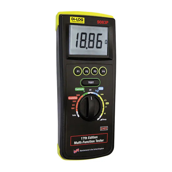
- Page 2 9083P Operating Instructions Multifunction Tester Figure 1 9083P Front View Figure 2 9083P End View 328A561 revision1.1 - 2 -...
- Page 3 9083P Operating Instructions Multifunction Tester Figure 3 Earth Continuity/Insulation Measurement Figure 4 Earth Continuity/Insulation Measurement using Cordless probe 328A561 revision1.1 - 3 -...
- Page 4 9083P Operating Instructions Multifunction Tester Figure 5 Voltage Measurement using test probes Figure 6 Earth Loop Impedance/Line Impedance/ RCD/ Mains Voltage Measurement 328A561 revision1.1 - 4 -...
- Page 5 9083P Operating Instructions Multifunction Tester Figure 7 Earth Loop Impedance/Line Impedance Figure 8 Line Impedance between phases 328A561 revision1.1 - 5 -...
-
Page 6: Limited Warranty & Limitation Of Liability
Operating Instructions Multifunction Tester Limited Warranty & Limitation of Liability DI-LOG Test Equipment guarantees this product to be free from defects in material and workmanship under normal use and service for a period of 2 year. The period of warranty will be effective at the day of delivery. -
Page 7: Table Of Contents
6.4 Line Impedance ..........26 6.5 RCD ..............26 6.6 Voltage/Frequency Measurement ....26 7 Environmental Conditions ........27 8 Maintenance............28 8.1 Preparing to work on the 9083P.......28 8.2 Securing the 9083P .........28 8.3 Cleaning ............29 8.4 Battery Replacement ........29 8.5 Replacing the Fuse..........30 8.6 Service and Calibration........30... -
Page 8: Certificate Of Conformity
CERTIFICATE OF CONFORMITY As the supplier of the apparatus listed, declare under our sole responsibility that the product: 9083P Multifunction Tester To which this declaration relates are in conformity with the relevant clauses of the following standard: BS EN 61010-1:2001 Safety requirements for electrical equipment for measurement, control, and laboratory use –... -
Page 9: Introduction
9083P Operating Instructions Multifunction Tester Introduction The 9083P is a hand held, battery powered, multi- function electrical installation test instrument capable of performing a comprehensive range of tests, including: Earth Continuity @ 200mA Insulation Resistance at 100V, 250V and 500V... -
Page 10: Safety Information
- the instrument does not function or - after long periods of storage under adverse environmental conditions. If the 9083P is used in a manner not specified by this document then the protection provided by the equipment may be impaired. -
Page 11: Accessories
9083P Operating Instructions Multifunction Tester 3 Accessories 3.1 Standard Accessories The 9083P is supplied with the following items: 1 off 9083P unit 1 off professional carry case 1 off Di-LOG mains test lead 1 off 1.2 M black test lead 1 off 1.2 M red test lead... -
Page 12: Unit Description
9083P Operating Instructions Multifunction Tester 4 Unit Description The 9083P is a hand held, multi-function electrical installation test instrument, capable of performing all of the required electrical tests. Tests are selected using the colour coded rotary switch. 4.1 Identifying parts of the unit The numbering below refers to figure 1 and figure 2. -
Page 13: Lcd Display
9083P Operating Instructions Multifunction Tester 4.2 LCD display 1. Mains supply status icons These icons indicate the status of the mains supply between phase-earth (PE), phase-neutral (PN) and phase-earth (PE) during RCD and Loop tests. Note: Testing is inhibited if the mains supply is incorrect. - Page 14 These icons are used to inform the user of the potential of any hazard or warning which may restrict the operation of the 9083P. Note: The 9083P is equipped with a thermal cut-out to protect against damage from excessive internal temperature. If the thermal cut-out is...
-
Page 15: Using The 9083P
Operating Instructions Multifunction Tester 5 Using the 9083P 5.1 Power On To turn the 9083P on simply rotate the rotary switch to the required test type. 5.2 Battery Health Check The 9083P will automatically perform battery health checks periodically or when a new test type is selected. - Page 16 If the test lead resistance is great than 10 ohms an error beep will indicate that the Lead Zero function has failed. Note: For ease of use, the 9083P will store the lead compensation when instrument...
-
Page 17: Insulation Resistance Tests
Use the rotary switch to select either the 100V, 250V or 500V MΩ test. The 9083P will display the Test Lock and battery symbol for 1 second. If the Test Lock feature is required, it should be activated as described below. -
Page 18: Voltage Measurement
To begin the test, press and release the TEST key. Note: The 9083P will determine the fault voltage that may appear on the protective conductor during the test. If the fault voltage is greater than 25V the 9083P will indicate >25V on the... -
Page 19: Auto Rcd Test Sequence
F1, without the need to repeat the test. 5.7 Auto RCD Test Sequence The 9083P will only allow the Earth Loop Impedance test to be performed if the correct voltages are detected between phase-neutral (PN illuminated), phase-earth (PE illuminated) and neutral-earth (NE not illuminated). - Page 20 During selective tests the 9083P will display a delay timer which counts down from 30s to 0s. Pressing the Test key or turning the rotary switch while the 9083P is counting will terminate the count. ac current / standard RCD...
-
Page 21: Rcd Trip Time Tests
100mA When the required settings have been selected, press the TEST key to begin the sequence. Note: The 9083P will determine the fault voltage that may appear on the protective conductor during the test. If the fault voltage is greater than 25V the 9083P will indicate >25V on the... - Page 22 During selective tests the 9083P will display a delay timer which counts down from 30s to 0s. Pressing the Test key or turning the rotary switch while the 9083P is counting will terminate the count. ac current / standard RCD...
-
Page 23: Rcd Trip Current (Ramp) Tests
(NE not illuminated). Leakage currents or voltage on the protective conductor may influence the measurement. Note: The 9083P will first perform a short pre-test to determine the fault voltage that may appear on the protective conductor during the test. If the fault voltage is greater than 50V then the 9083P will indicate >50V on the LCD, the test... - Page 24 During selective tests the 9083P will display a delay timer which counts down from 30s to 0s. Pressing the Test key or turning the rotary switch while the 9083P is counting will terminate the count. Rated residual operating current I∆n (F4) The rated residual operating current is selected by pressing the F4 key.
-
Page 25: Electrical Specifications
9083P Operating Instructions Multifunction Tester 6 Electrical Specifications 6.1 Earth Continuity Test Voltage Open Circuit >4V Test Current >200mA into 2Ω Display Range 0.00Ω - 199Ω Measuring Range 0.01Ω – 1.99Ω 2.0Ω – 19.9Ω 20Ω – 199Ω Resolution 0.01Ω maximum Accuracy ±2% ±5 digits... -
Page 26: Line Impedance
9083P Operating Instructions Multifunction Tester 6.4 Line Impedance Supply Voltage 195V – 440V, 45Hz – 65Hz Nominal Test Current 15mA Display Range 0.01Ω - 2000Ω Measuring Range 0.05Ω - 1.99Ω 2.0Ω – 19.9Ω 20Ω - 2000Ω Resolution 0.01Ω maximum Accuracy ±5% ±2 digits... -
Page 27: Environmental Conditions
61326-1. Operating temperature range of 0°C to 40°C, without moisture condensation. The 9083P can be stored at any temperature in the range -25°C to +65°C (relative humidity up to 90%). The batteries should be taken out of the instrument for storage. -
Page 28: Maintenance
Electric shock danger! 8.1 Preparing to work on the 9083P. Ensure that the 9083P is voltage free as follows, before opening the instrument; Power the unit off using the rotary switch by selecting the Off position on the rotary switch. -
Page 29: Cleaning
9083P Operating Instructions Multifunction Tester 8.3 Cleaning Clean the external case of the 9083P with a clean dry cloth. Avoid using solvents and abrasive scouring agents to clean the external case of the 9083P. Check the battery contacts and compartment are free of electrolytic contamination. -
Page 30: Replacing The Fuse
Power the unit off by selecting the Off position on the rotary switch. Disconnect all the test leads from the unit. Position the 9083P face down and release the captive screw in the battery compartment cover. Remove the battery compartment cover. -
Page 31: Spare Parts
43B721 Carrying Case 328A953 3.15A T 500V 1¼” 27B083 For help or advice on Service and Calibration contact: Service Department Di-LOG Test Equipment 28 Wheel Forge Way Trafford Park Manchester M17 1EH Freefone: 0800 018 9122 Freefax: 0800 018 6711 Email: sales@dilog.co.uk...
Need help?
Do you have a question about the 9083P and is the answer not in the manual?
Questions and answers