Table of Contents
Advertisement
Utility Line Locator
SERVICE CENTER, SALES AND TECHNICAL SUPPORT INFORMATION
Vivax-Metrotech Corporation
3251 Olcott Street,
Santa Clara, CA 95054, USA
Website : www.vivax-metrotech.com
Sales & Sales Support:
T/Free : +1-800-446-3392
Tel
: +1-408-734-1400
Fax
: +1-408-734-1415
Email
: sales@metrotech.com
Application Support:
T/Free : +1-800-624-6210
Tel
: +1-408-454-7159
Fax
: +1-408-743-5597
Email
: applications@metrotech.com
Warranty: One year. Specifications Subject to change without notice, ISO 9001:2000 Certified. Copyright 2008. All Rights Reserved.
9800 XT™
Service & Repairs:
T/Free
: +1-800-638-7682
Tel
: +1-408-962-9990
Fax
: +1-408-734-1799
Email
: service@metrotech.com
All Other Department:
T/Free
: +1-877-330-1647
Tel
: +1-408-734-3880
Fax
: +1-408-962-9993
Page 1 of 45
OPERATIONS MANUAL
CanadaVivax Canada Inc.
400 Esna Park Drive,
Unit 17, Markham,
Ontario, L3R 3K2, Canada
Tel
: +1-289-846-3010
Website : www.vivax-metrotech.com
Email
: CanadianSales@vivax.biz
EuropeSebaKMT
Seba Dynatronic
Mess-und Ortungstechnik GmbH
Dr.-Herbert-Iann-Str. 6,
96148 Baunach, Germany.
Tel
: +49-9544-680
Fax
: +49-9544-2273
Website : www.sebakmt.com
Email
: service@sebakmt.com
Australasia SebaKMT AUS
Unit 1, 176 South Creek Road,
Cromer NSW 2009, Australia
Tel
: +61-2-9972-9244
Fax
: +61-2-9972-9433
Website : www.sebakmtaus.com
Email
: sales@sebakmtaus.com
service@sebakmtaus.com
Leidi Utility Supply (Shanghai) Ltd.
Rm405 3rd Building No. 641, Tianshan
Rd,
Shanghai, China 200336
Tel
: +86-21-5187-3880
Fax
: +86-21-5168-5880
Website : www.leidi.com
Email
: info@leidi.cn
Rev 12/01/07 E
Advertisement
Table of Contents

Summary of Contents for Vivax 9800 XT
- Page 1 OPERATIONS MANUAL 9800 XT™ Utility Line Locator SERVICE CENTER, SALES AND TECHNICAL SUPPORT INFORMATION Vivax-Metrotech Corporation CanadaVivax Canada Inc. Australasia SebaKMT AUS 3251 Olcott Street, 400 Esna Park Drive, Unit 1, 176 South Creek Road, Santa Clara, CA 95054, USA...
- Page 2 ISO 9001 CERTIFIED Metrotech has received ISO 9001 Quality Management System Certification. Metrotech adheres to the quality standard guidelines of ISO 9001 and ensures quality in its design/development, production, installation, and servicing disciplines. © Metrotech Corporation -2008 Metrotech Corporation 3251 Olcott Street Santa Clara, CA 95054 Tel: 1.800.446.3392;...
-
Page 3: Table Of Contents
TABLE OF CONTENTS List of Illustrations 1 Introduction 2 Safety Precautions 3 9800XT Quick Start Guide for the Experienced User 4 Model 9800XT Equipment Standard Equipment Optional Features on Standard Equipment Accessories Technical Specifications Transmitter:Controls, Indicators, and Features Receiver: Controls and Indicators, Features 5 Checkout Procedure 6 Operation... -
Page 4: List Of Illustrations
Batteries Service Center Information Appendix Copyright Notice Warranty List of Illustrations Figure 4-1: Model 9800XT Utility Line Locator - Standard and Optional Equipment Figure 4-2: 9800XT Transmitter: Controls and Indicators Figure 4-3: 9800XT Receiver - Controls and Indicators Figure 4-4: 9800XT Receiver LCD Display Figure 4-5: 9800XT Receiver LCD Display: Depth Measurement Mode Figure 5-1: Connect Transmitter Leads... - Page 5 Figure 7-2: Adjacent Conductors - Position of Ground Lead Figure 7-3: Locating Service Laterals Figure 7-4: Locating a Bend Figure 7-5: Locating a Dead End Figure 7-6: Incorrect Coupling for Congested Area Figure 7-7: Correct Coupling for Congested Area Figure 8-1: Replacing the Non- rechargeable D-Cell Transmitter Batteries Figure 8-2: Recharging the Rechargeable NiCd Transmitter Battery with the Wall...
-
Page 6: Introduction
1 INTRODUCTION This manual describes the Metrotech Model 9800XT Utility Line Locator. Included is an equipment description, product specifications, checkout procedures, operating procedures, application information and maintenance instructions. The Model 9800XT is a series of state-of-the-art utility line locators precisely designed with many powerful features to provide you with optimum information about your locate situation. -
Page 7: Model 9800Xt Equipment
Adjust Receiver Controls - Turn Receiver “ON” and select frequency. default, the unit will operate in “Auto” gain mode. Sweep Area Around Transmitter – Circle Transmitter with Receiver at a distance of 10 feet (3 m). Left/Right display and Receiver signal strength will indicate location of buried conductors. -
Page 8: Accessories
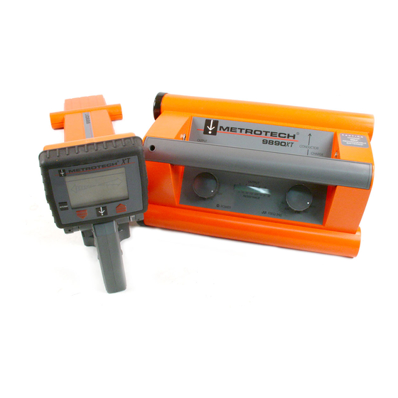
Figure 4-1: Model 9800XT Utility Line Locator - Standard and Optional Equipment Standard: 1. 9800XT Receiver 2. 9800XT Transmitter 3. Conductive Attachment 4. Ground Rod 5. Ground Plate 6. Safety Flag 7. Carrying Case Options: 8. SFL – 2 Receiver Accessories: 9. -
Page 9: Technical Specifications
Cable ID 4490 4” Metroclamp and For Inductive jumper cable Coupling or Cable ID 4890 8” Metroclamp and For Inductive jumper cable Coupling or Cable ID 400B246 Conductive Attachment Telephone style Clips 400A132 100’ Ground Lead Extension 400B252 Vehicle Mount Charger For use with rechargeable transmitter batteries 183048... - Page 10 Optional Rechargeable NiCd Battery Life: Alkaline 28-70 hours NiCd 9-22 hours Continuous use, depending on power and Frequency selection. Battery Check: Automatic at start up Operation Temperature: -4º to +122º F (-20º to +50º C) Dimensions: 14.25”L x 9.25”W x 5.25”H (36.2 cm x 23.5 cm x 13.3 cm) Weight:...
-
Page 11: Transmitter:controls, Indicators, And Features
Inductive mode. CHARGE JACK (Optional Feature) - If you have purchased a 9800 XT with the Rechargeable NiCd Battery feature, your Transmitter will have a jack for connecting the Wall Mount Charger or the Vehicle Mount Charger. The Jack is located on the right inside wall of the Transmitter. -
Page 12: Figure 4-2: 9800Xt Transmitter: Controls And Indicators
9800XT TRANSMITTER Figure 4-2: 9800XT Transmitter: Controls and Indicators 1 Output Jack 2 Conductor Arrow 3 Charge Jack 4 Frequency Knob 5 LCD Display 6 Power Knob 7 Battery Access Caps LCD BARGRAPH DISPLAY - The bargraph indicates four types of information: BATTERY STATUS - First 3 seconds the amount of Transmitter battery charge is indicated by the number of bars illuminated. - Page 13 POOR CONDUCTOR AND IMPROPER SELECTION - Entire display blinks and Transmitter beeps very fast or emits a constant beeping tone. SPEAKER (not shown) - Transmitter audio tone changes according to operating function: Speaker Tone Description Every 5 seconds Good transmitter connection Very fast Low battery warning and poor conductor alert...
- Page 14 4.5.2 Transmitter Features Automatic Best Frequency Selection - Chooses the lowest frequency that provides reliable Receiver response in a typical 500 ft. locate. Poor Conductor Alert - Warns the user that no frequency will produce a reliable Receiver response. Automatic Impedance Matching - Automatically matches the Transmitter to the line impedance to provide maximum output in all situations.
-
Page 15: Receiver: Controls And Indicators, Features
9800XT RECEIVER Figure 4-3: 9800XT Receiver - Controls and Indicators GAIN SETTING BATTERY OPERATING STATUS FREQUENCY Gain AUTO/MANUAL GAIN INDICATOR SIGNAL STRENGTH AUTO/MANUAL GAIN Rs232 SERIAL PORT ON/OFF/ VOLUME KNOB 4.6 Receiver: Controls and Indicators, Features 4.6.1 Receiver Controls and Indicators See Figure 4.3 for the location of the controls and indicators described below: ON/OFF VOLUME KNOB - Turn clockwise to turn unit “ON”. -
Page 16: Figure 4-4: 9800Xt Receiver Lcd Display
LCD DISPLAY (Liquid Crystal Display) - Displays the battery status, operating frequency, Distance Sensitive Left/Right Guidance™, gain setting, and signal strength. Figure 4-4: 9800XT Receiver LCD Display Battery Status Operating Frequency Distance Sensitive Left/Right Guidance Signal Strength In the Depth Measurement mode it displays the battery status, current measurement, and depth measurement. - Page 17 AUX JACK (Left side under display head) - Plug Metroclamp into this jack. Used to identify one conductor out of a group of conductors. HEADPHONE JACK (Right side under display head) - Plug headphones into this jack. SPEAKER (Under the display head) - Emits audio tone to guide operator toward the targeted conductor.
-
Page 18: Checkout Procedure
Depth Measurement to 20 Feet (6 m) - Depth measurement range is up to 20 feet (6 m) to provide information for deep locates. RS232 Serial Communication Port - Provides data transfer capability for calibration and service. Not mention conversion of 50Hz to 60Hz until works on 9890XT? 5 CHECKOUT PROCEDURE To ensure proper operation of the Model 9800XT Utility Line Locator, use the checkout procedure below at the following times:... -
Page 19: Operation
Figure 5-1: Connect Transmitter Leads Figure 5-2: Aim Receiver at Transmitter 6 OPERATION Follow the Checkout Procedure described in Section 5 before operating the equipment. To operate the 9800XT Utility Line Locator use the Transmitter to apply the signal to the conductor, and use the Receiver to trace the signal from the conductor. -
Page 20: Transmitter Set-Up
6.1 Transmitter Set-up 6.1.1 Check the Battery - Turn the Transmitter “ON” by turning the left knob to “L” (low). Battery status will be indicated by the number of bars on the LCD. 100% charge - 11-12 bars 50% charge - 5-6 bars 25% charge - 1-3 bars The audio tone will also indicate the battery status - a slow beep indicates the batteries are sufficiently charged. -
Page 21: Figure 6-1: Direct (Conductive) Connection
improve conductivity, put water and/or a weight on the plate. See Figure 6-1. Select a frequency - The 9860XT Transmitter offers two active frequencies - 9.82kHz and 82kHz. The 9890XT Transmitter has three active frequencies - 982Hz, 9.82kHz, and 82kHz. Figure 6-1: Direct (Conductive) Connection The Auto and ALL selections behave differently according to the mode of locating you are working... - Page 22 All (9890XT Transmitter) Simultaneous 982Hz, 9.82kHz, and 82kHz Select Transmitter output power - All 9800XT Transmitter models have three output power settings - Low, Medium, and High. Power output will change according to the frequency selected As shown on the next page. Transmitter Output Setting Frequency...
- Page 23 Place an inductive Metroclamp around the conductor. The Transmitter clamps are available for use with the 9800XT. Metroclamp Ground Requirements - If you are using the Metroclamp around a cable, both ends of the cable must be grounded. This ensures a ground return path for optimum current flow (signal strength).
-
Page 24: Figure 6-2: Inductive Coupling With The Metroclamp
Figure 6-2: Inductive Coupling with the Metroclamp Turn the Transmitter to “L” - The Transmitter will first display battery life. Then the display will show blinking right and left arrows. Trace your conductor - Refer to Section 6.2 for tracing instructions. C Inductive (Indirect Method) - This is the least effective method of applying signal to isolate one conductor. -
Page 25: Receiver Operation
Transmitter. Make sure the arrow is directly over the targeted conductor. See Figure 6- Figure 6-3: Transmitter Position for Inductive Tracing Select a frequency - Transmitter Behavior - Inductive Mode Switch Position Inductive Auto Defaults to 82kHz 982Hz No output - do not use 9.82kHz Good for cables 82kHz... - Page 26 Set the frequency - Turn the left hand knob to set the Receiver to the desired frequency. The selected frequency will appear in the upper right hand corner of the LCD display. If you are locating actively, you need to match the frequency to that of the Transmitter.
-
Page 27: Figure 6-4: Receiver Position For Tracing
Figure 6-4: Receiver Position for Tracing Distance Sensitive Left/Right Guidance - will visually guide you to your conductor. When the bar is to the left, move to the left. When the bar is to the right, move to the right. When you are centered over the conductor, the vertical bar will be centered between the arrows. - Page 28 Switching between automatic and manual gain control mode - To adjust the gain manually, push the ”Auto/Man” button once. ”MAN” appears on the display when in the manual gain control mode. Adjust the gain up or down using the red up/down arrow buttons.
-
Page 29: Figure 6-5: Receiver Position When Determining Depth
When determining depth in an active mode, the Receiver Left/Right Guidance System must be centered within 3 bars from the centerline in order to get a depth reading. If it is not, the unit will beep and display “CL” (center line) when you push the depth arrow button. -
Page 30: Figure 6-6: Principle Of Triangulation
completely and the audible tone is continuous (gain is too high). Adjust the gain upwards pressing the red gain up arrow button if the “curtain” displays nothing and there is no tone (gain is too low). The selected gain setting will be indicated on the Receiver LCD display in the upper left corner. -
Page 31: Figure 6-7: Receiver Position For Triangulation
Figure 6-7: Receiver Position for Triangulation Figure 6-8: Locate Centerline 6.2.5 Triangulation for Confirming Presence of Common Trench Conductors - If you are locating a conductor in a common trench, your signal may induce onto a more shallow or better conductor. When this occurs, you may get an unlikely depth reading using the Receiver push button depth measurement function. -
Page 32: Advanced Techniques
Figure 6-9: Multiple Conductors in a Common Trench 7 ADVANCED TECHNIQUES 7.1 Ground Survey - Regulations at construction sites often require a ground survey before any excavation is done. This prevents damaging underground utilities. A ground survey is a process to locate all the underground conductors within a particular area. It includes standard locating and a blind search. -
Page 33: Figure 7-1: Blind Search Parallel Pattern
Operator 1 holds the Transmitter at his/her side and level with the ground. Operator 2 holds the Receiver vertically at his/her side with the top surface of the Receiver facing the Transmitter. Walk together across the search area. The Receiver Left/Right and the signal strength reading will indicate the presence of a conductor under the ground as the operators pass over it. -
Page 34: Adjacent Conductors
Figure 7-2: Adjacent Conductors - Position of Ground Lead Move Ground Away From PPE 7.3 Deep Conductor - Signals picked up by the Receiver from deeply buried pipes are weaker and not as directionally distinct as those from pipes closer to the surface. In addition, the signal strength will only change by small increments in relation to moving the Receiver antenna. -
Page 35: Valves, Manhole Cover, T's And Risers
If you pivot all the way around (360 degrees), without getting any noticeable signal strength, it means you have reached a dead end. See Figure 7-5. 7.7 Valves, Manhole Cover, T’s and Risers - If the signal strength suddenly increases and then falls back while tracing a pipe you have probably passed over a buried valve, manhole cover, T, or riser. -
Page 36: Common Bonded Conductors
Figure 7-5: Locating a Dead End 7.8 Common Bonded Conductors - Telephone, power, and CATV sometimes use a common ground bond. If other conductors are connected to your target conductor, putting a signal on the target can cause all the conductors to carry the same signal, making it difficult to identify the target conductor. -
Page 37: Figure 7-6: Incorrect Coupling For Congested Area
Determine the location of the adjacent conductors. Then check to be sure that neither the direct connect cable or the ground cable cross over any of the adjacent conductors. Reposition them if necessary. If you are inducing, you can decrease the interfering signal by changing the position of the Transmitter. -
Page 38: Determining If You Have A "Ghost" Conductor
Figure 7-7: Correct Coupling for Congested Area 7.11 Determining If You Have a “Ghost” Conductor - If there is another conductor near your target conductor, it too may pick up signal from the Transmitter. When this occurs, there will seem to be a ”ghost” between the two conductors. You are likely to have a ”ghost”... -
Page 39: Non-Metallic Pipes
to a ground spike at the end of a service, where the pipe or tracer wire comes out of the earth. Be sure to remove the ground connection after completing the locate so as not to defeat the cathodic protection system. 7.14 Non-Metallic Pipes - To trace nonmetallic pipe (sewer line) or duct, send the signal through the pipe by inserting the appropriate Metrotech Sonde (according to the operating frequency you are using). -
Page 40: Replacing The 9800Xt Non- Rechargeable D-Cell Transmitter Batteries
Figure 8-1: Replacing the Non-rechargeable D-Cell Transmitter Batteries Figure 8-2: Recharging the Rechargeable NiCd Transmitter Battery with the Wall Mount Charger 8.2 Recharging the 9800XT Transmitter NiCd Rechargeable Battery - If you have purchased a 9800XT with a rechargeable NiCd Transmitter battery, you will have received a Wall Mount Charger. -
Page 41: Figure 8-3: Recharging The Rechargeable Nicd Transmitter Battery With The Vehicle Mount Charger
To check the amount of Transmitter charge, unplug the wall mount from the Transmitter and turn the Transmitter to ”L”. The LCD bars will indicate the amount of charge in the Transmitter. 8.2.2 Vehicle Mount Charger (VMC) - The Vehicle Mount Charger provides an ”at the site”... -
Page 42: Replacing The 9800Xt Receiver
Figure 8-4: Replacing the 9800XT Receiver Batteries 8.3 Replacing the 9800XT Receiver Batteries - See Figure 8-4. Have ready six AA batteries. Using a screwdriver or dime, turn the two spring-loaded quarter-turn screws on the underside of the 9800XT Receiver handle and remove the battery housing cover. -
Page 43: Service Center Information
Metrotech Customer Service departments: Vivax-Metrotech Corporation EuropeSebaKMT 3251 Olcott Street, Seba Dynatronic Santa Clara, CA 95054, USA Mess-und Ortungstechnik GmbH Website : www.vivax-metrotech.com Dr.-Herbert-Iann-Str. 6, Sales & Sales Support: 96148 Baunach, Germany. T/Free : +1-800-446-3392 : +49-9544-680 : +1-408-734-1400 : +49-9544-2273 : +1-408-734-1415 Website : www.sebakmt.com... -
Page 44: Appendix
APPENDIX A1 APWA Marking Colors - The following color markings have been established by the American Public Works Association (APWA): Conductor Color Electric power lines, cables, or conduits Communication lines, cables, conduits, CATV Orange Gas, oil, petroleum, or other gaseous materials Yellow Sewers, storm and sanitary, drain lines... -
Page 45: Copyright Notice
COPYRIGHT NOTICE The information contained in this document is for informational purposes only and is subject to change without notice. Metrotech Corporation makes no warranty of any kind with regard to the information contained in this manual, including but not limited to the implied warranties of merchantability and fitness for a particular purpose.
Need help?
Do you have a question about the 9800 XT and is the answer not in the manual?
Questions and answers