Table of Contents
Advertisement
Quick Links
Advertisement
Table of Contents

Related Manuals for ENDEAVOUR E40

Summary of Contents for ENDEAVOUR E40
- Page 1 ENDEAVOUR 40 OWNERS MANUAL...
-
Page 2: Table Of Contents
ENDEAVOUR 40 OWNERS MANUAL Table of Contents 1. Introduction 2. List of Figures 3. Construction 3.1 Hull 3.2 Deck 3.3 Deck/Hull Joint 3.4 Rudder and Steering 3.5 Ballast 3.6 Interior Construction 4. Spars and Rigging 4.1 Spars 4.2 Standing Rigging, Running Rigging, Chainplates 4.3 Static Tuning (at the Dock) -
Page 3: List Of Figures
9. Plumbing System 9.1 Head and Holding Tank 9.2 Galley Stove Operation 10. Maintenance 10.1 Gelcoat Surfaces 10.2 Ports and Hatches 10.3 Teak 10.4 Hull Bottom 10.5 Standing Rigging 10.6 Running Rigging 10.7 Lifelines, Pulpits, Stanchions 10.8 Winches and Block 10.9 Engine 10.10 Power Train 10.11 Electrical Maintenance... -
Page 4: Construction
3.3) Deck/Hull Joint: The joint between the hull and deck is one of the most important assembly steps in the construction of a yacht. The method used by Endeavour Yacht is simple, strong, and reliable. Figure #1 illustrates details of this assembly. -
Page 5: Ballast
3.6) Interior Construction: The interior of your Endeavour 40 is built up of wood. First, a framework of floor timbers is constructed and placed in the bilge and heavily bonded in place with woven roving. A plywood sole is glued and screwed on top of these floor timbers and bonded to the hull all around its periphery with woven roving. -
Page 6: Spars And Rigging
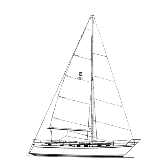
SPARS AND RIGGING 4.1) Spars: All spars (masts, booms, and spreaders) are extruded aluminum 6061-T6 alloy with a protective coating on all external surfaces. The main mast of the E-43 is stepped through the cabin roof onto the keel. The mizzen mast is stepped on deck with a supporting post or structure immediately under the mast. -
Page 7: Dynamic Tuning (Under Sail)
particular part of the rail or deck you choose as your reference point is not important as long as it is the same point on each side After the mast is centered transversely, tighten both upper shroud turnbuckles uniformly, one full turn on one side, then one full turn of the other. Repeat until the turnbuckles become difficult to turn. - Page 8 RIGGING SPECIFICATIONS All lengths pin to pin ENDEAVOUR- 40 MAIN SLOOP LENGTH DIAMETER HEADSTAY 51’ 6” 3/8” BACKSTAY 53’ 9½” 3/8” UPPER SHROUDS 49’ 9½” 5/16” LOWER FWD SHROUDS 26’ 2½” 5/16” LOWER AFT SHROUDS 26’ 4” 5/16” 4.5) Reefing: A) How to Setup Boom 1.
-
Page 9: Fuel System
ENGINE AND TRANSMISSION OF POWER 6.1) Engine: All Endeavour models are equipped with inboard diesel engines. All necessary data and information is contained in the Engine Owner’s Manual and is not repeated here. Read this manual carefully. Get to know your engine well and give it proper maintenance to have... -
Page 10: Transmissions
Replace the alien screws when in place. 6.4) Shaft Alignment: All new Endeavour yachts are shipped with the shaft coupling disconnected to ensure that alignment is performed after delivery. All molded fiberglass boats will change shape slightly when launched, causing the relationship between the engine and propeller shaft to change. -
Page 11: Propellers
6.5) Propellers: The standard propeller supplied with all Endeavour models is a solid bronze, two-bladed type. It has a tapered bore that mates to a tapered shaft end and is held in place with two locking nuts and a cotter pin. -
Page 12: Exhaust System
6.9) Exhaust System: In the Perkins engine, a water pump draws water through the intake port, circulates it through a heat exchanger, where it is pumped in the muffler and overboard through the exhaust port. The salt water in the heat exchanger lowers the temperature of the engine coolant circulated through the engine block by means of the normal engine water pump. -
Page 13: Starting The Engine
ELECTRICAL SYSTEM 8.1) General: The electrical system in your Endeavour yacht has been designed to ensure as much trouble-free operation as possible. Wiring and connections are kept as high in the interior of the yacht as practical to reduce exposure to water. Virtually all wiring and connections are accessible by removing panels from under the side decks. -
Page 14: Direct Current (D.c.) System
Metallic fittings (through hulls, etc.) below the water line are electrically bonded together with green plastic coated 8 gauge copper wire and connected to a common ship’s ground. This is done to minimize the effect of electrolytic action when the boat is used in salt water. 8.2) Direct Current (D.C.) System: The D.C. -
Page 15: Plumbing System
Government regulations require all U.S. yacht manufacturers to install a holding tank system or approved waste treatment system to prevent water pollution. All Endeavour yachts are provided with plastic holding tanks with deck pump out fittings for this purpose. However, a... - Page 16 9.2) Galley Oven Range: The Endeavour 40 is equipped with either an alcohol oven range or a gas oven range. All necessary data and information is contained in the range manufacturer’s manual and is not repeated here. Figures #7 and #8 describe the plumbing system for these ranges.
-
Page 17: Maintenance
MAINTENANCE All yachts require maintenance on a regular basis to stay in top operating condition and to keep looking their best. One should constantly check running and standing rigging, winches, engine, head, bilge, and surface finishes for telltale signs of needed maintenance. 10.1) Gelcoat Surfaces: The best protection for your gelcoat surfaces is to clean them regularly with fresh water and a good detergent. -
Page 18: Ports And Hatches
Coat the vinyl with paste wax before applying to facilitate removal. This vinyl fabric material is available from Endeavour Yacht on request. When the putty is cured, peel off the vinyl and blend the edges of the repair with a sharp knife. Minor touch up with gel putty around the repair edge may also be required to blend the patch. -
Page 19: After Launching
11.2) After Launching: A) Check all through hull fittings, gate valves, sea cocks, and the bilge to ensure that leakage is not occurring. B) Open the valve for the engine cooling water intake. C) Turn on main power switch and bilge blower. D) Use hand primer located at fuel pump to charge the fuel system. -
Page 20: Laying Up For Winter Storage
Release lower shrouds from their lashing, connect the lower shrouds and snug up all turnbuckles. Replace clevis pins and cotter pins. To help prevent damage to sails, insert all clevis pins fore to aft or outboard to inboard and tape over the cotter pins. Release all running rigging and lead to the appropriate blocks and winches. -
Page 21: Batteries
20’ Between Straps This is a copy of the original Endeavour 40 owners manual. Efforts were make to keep the original content accurate, however transcription errors may exist. Philip N. Johnson...
Need help?
Do you have a question about the E40 and is the answer not in the manual?
Questions and answers