Table of Contents
Advertisement
ALL phases of this installation must comply with NATIONAL, STATE AND LOCAL CODES
IMPOrTANT — This Document is customer property and is to remain with this unit. Please return to service information pack
upon completion of work.
These instructions do not cover all variations in systems
nor provide for every possible contingency to be met in
connection with installation. All phases of this installa-
tion must comply with NATIONAL, STATE AND LOCAL
CODES.
Should further information be desired or should
particular problems arise which are not covered sufficiently for
the purchaser's purposes, the matter should be referred to your
installing dealer or local distributor.
A. GENErAL
wARNING:
▲
for use by individuals possessing adequate backgrounds
of electrical and mechanical experience. Any attempt to
repair a central air conditioning product may result in
personal injury and or property damage. The manufac-
turer or seller cannot be responsible for the interpreta-
tion of this information, nor can it assume any liability
in connection with its use.
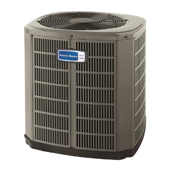
The following instructions cover 4A6H3 Heat Pump Units.
NOTE:
AMERICAN STANDARD HAS ALWAYS REC-
OMMENDED INSTALLING AMERICAN STANDARD
APPROVED MATCHED INDOOR AND OUTDOOR SYS-
TEMS.
THE BENEFITS OF INSTALLING APPROVED INDOOR
AND OUTDOOR SPLIT SYSTEMS ARE MAXIMUM EF-
FECIENCY, OPTIMUM PERFORMANCE AND THE BEST
OVERALL SYSTEM RELIABILITY.
wARNING:
▲
ant which operates at 50 to 70% higher pressures than r-22.
Use only r-410A approved service equipment. refrigerant
cylinders are painted a "rose" color to indicate the type
of refrigerant and may contain a "dip" tube to allow for
charging of liquid refrigerant into the system. All r-410A
systems use a POE oil that readily absorbs moisture from
the atmosphere. To limit this "hygroscopic" action, the
system should remain sealed whenever possible. If a
system has been open to the atmosphere for more than 4
hours, the compressor oil must be replaced. Never break a
vacuum with air and always change the driers when open-
ing the system for component replacement. For specific
handling concerns with r-410A and POE oil, reference
retrofit Bulletin SSC-APG011-EN.
Check for transportation damage after unit is uncrated. Report
promptly, to the carrier, any damage found to the unit.
© 2011 American Standard Heating & Air Conditioning
INSTALLER'S GUIDE
Heat Pumps
Models:
This information is intended
These units use r-410A refriger-
4A6H4
UNIT coNTAINS R-410A REfRIGERANT!
R-410A OPERATING PRESSURE EXCEEDS THE
LIMIT OF R-22. PROPER SERVICE EQUIPMENT IS
REQUIRED. FAILURE TO USE PROPER SERVICE
TOOLS MAY RESULT IN EQUIPMENT DAMAGE OR
PERSONAL INJURY.
USE ONLY R-410A REFRIGERANT AND
APPROVED POE COMPRESSOR OIL.
5 fT. AbovE UNIT-UNRESTRIcTED
1
To determine the electrical power requirements of the unit, refer
to the nameplate of the unit. The electrical power available must
agree with that listed on the nameplate.
The Heat Pump has been designed and manufactured to with-
stand and operate in severe winter conditions. However, there
are precautionary steps which should be taken at the time of
installation which will help assure the efficient operation of
the unit.
Available in French Canadian (FC)
11-BC08D1-7
cAUTIoN
!
SERvIcE
Since the manufacturer has a policy of continuous product
and product data improvement, it reserves the right to
change design and specifications without notice.
Advertisement
Table of Contents

Summary of Contents for American Standart 4A6H4
- Page 1 INSTALLER'S GUIDE ALL phases of this installation must comply with NATIONAL, STATE AND LOCAL CODES Heat Pumps 4A6H4 Models: IMPOrTANT — This Document is customer property and is to remain with this unit. Please return to service information pack upon completion of work.
-
Page 2: Installer's Guide
INSTALLER'S GUIDE 2. The unit should be set on a level support pad at least as large as the unit base pan, such as a concrete slab. If this is not the bASEPAN TAb REMovAL application used please refer to application bulletin AMSSP- APG002-EN. -
Page 3: Brazing Refrigerant Lines
INSTALLER'S GUIDE GAS LINE SERvIcE vALvE GAS LINE bALL SERvIcE vALvE 1/4 TURN oNLy coUNTERcLockwISE foR fULL oPEN PoSITIoN vALvE STEM UNIT SIDE of vALvE PRESSURE TAP PoRT GAS LINE coNNEcTIoN The Gas Line Service Valve is full open with a 1/4 turn. See Figure 4. - Page 4 INSTALLER'S GUIDE 2. Attach appropriate hoses from manifold gauge to gas and PIN IDENTIfIcATIoN liquid line pressure taps. NOTE: Unnecessary switching of hoses can be avoided and complete evacuation of all lines leading to sealed system can be accomplished with manifold center hose and connecting branch hose to a cylinder of R-410A and vacuum pump.
-
Page 5: Electric Heaters
INSTALLER'S GUIDE k. SEACOAST SALT ShIELD If a defrost control problem is suspected, refer to the service in- formation in control box. If installed within one mile of salt water, including seacoasts and G. COMPrESSOr STArT-UP inland waterways, models without factory supplied Seacoast Salt Shields require the addition of BAYSEAC001 (Seacoast Kit) at After all electrical wiring is complete, SET THERMOSTAT SYS- installation time. -
Page 6: Subcooling Charging In Cooling Above 55°F Od Ambient
INSTALLER'S GUIDE SUbcooLING cHARGING IN cooLING AbovE 55°f oD AMbIENT American Standard has always recommended installing approved R-410A SUbcooLING cHARGING TAbLE matched indoor and outdoor systems. DESIGN SUBCOOLING VALUES (°F) All American Standard split systems are AHRI rated with only LIQUID TXV indoor systems. - Page 7 INSTALLER'S GUIDE 4A6H4 oUTLINE DRAwING NoTE: ALL DIMENSIoNS ARE IN MM (INcHES). MODELS BASE FIG. 4A6H4018B 933 (36-3/4) 829 (32-5/8) 756 (29-3/4) 143 (5-5/8) 92 (3-5/8) 210 (8-1/4) 79 (3-1/8) 508 (20) 4A6H4024B 1035 (40-3/4) 829 (32-5/8) 756 (29-3/4) 5/16...
-
Page 8: Mounting Hole Location
INSTALLER'S GUIDE MoUNTING HoLE LocATIoN NoTE: ALL DIMENSIoNS ARE IN MM (INcHES). NOTE: For model base size, see table on page 7. From Dwg. D152637 Rev. 2 cHEckoUT PRocEDURE After installation has been completed, it is recommended that the entire system be checked against the following list: 1.
Need help?
Do you have a question about the 4A6H4 and is the answer not in the manual?
Questions and answers