Table of Contents
Advertisement
Quick Links
Advertisement
Table of Contents

Related Manuals for Eagle E-DVR-104

Summary of Contents for Eagle E-DVR-104
-
Page 3: Compliance Notice Of Fcc
4- & 8- Channel Digital Video Recorder WARNING RISK OF ELECTRIC SHOCK DO NOT OPEN WARNING: TO REDUCE THE RISK OF ELECTRIC SHOCK, DO NOT REMOVE COVER (OR BACK). NO USER-SERVICEABLE PARTS INSIDE. REFER SERVICING TO QUALIFIED SERVICE PERSONNEL. The lightning flash with arrowhead symbol, within an equilateral triangle, is intended to alert the user to the presence of uninsulated "dangerous voltage"... -
Page 4: Important Safeguards
User’s Manual Important Safeguards 1. Read Instructions 10. Overloading All the safety and operating instructions should be read before the Do not overload wall outlets and extension cords as this can result appliance is operated. in the risk of fire or electric shock. 2. -
Page 5: Table Of Contents
4- & 8- Channel Digital Video Recorder Table of Contents Chapter 1 Introduction ....................1 Features ........................1 Technical Overview ....................1 Chapter 2 Installation ....................3 Package Contents ....................3 Required Installation Tools ..................3 Video Input ......................3 Audio In/Out ...................... - Page 6 User’s Manual Back Up Button ....................12 Calendar Button ....................12 Turning on the Power ..................... 12 Initial Unit Setup ..................... 12 Setup Screen ......................13 System Setup ......................14 Information ......................14 Date/Time ......................16 Storage ....................... 18 User ........................19 Wizard ........................
- Page 7 4- & 8- Channel Digital Video Recorder Playing Recorded Video ..................62 Searching Video ..................... 63 Search Menu ...................... 63 Event Log Search ....................65 Record Table Search ..................67 Motion Search ....................68 Text-In Search ....................70 Clip-Copy ......................71 Appendix ........................
- Page 8 User’s Manual Figure 19 Shutdown screen....................25 Figure 20 Network menu...................... 25 Figure 21 Network setup screen................... 25 Figure 22 LAN (Manual) setup screen.................. 26 Figure 23 DVRNS setup screen................... 28 Figure 24 RTSP setup screen....................29 Figure 25 WebGuard setup screen.
-
Page 9: Chapter 1 Introduction
4- & 8-Channel Digital Video Recorder Chapter 1 Introduction Features Your color digital video recorder (DVR) provides recording capabilities for four or eight camera inputs. It provides exceptional picture quality in both live and playback modes, and offers the following features: y 4 or 8 Composite Video Input Connectors y Compatible with Color (NTSC or PAL) and B&W (CCIR and EIA-170) Video Sources y Auto Detection for NTSC and PAL... -
Page 10: Figure 1 Typical Dvr Installation
User’s Manual Your DVR can be set up for event or time-lapse recording. You can define times to record, and the schedule can change for different days of the week and user defined holidays. The DVR can be set up to alert you when the hard disk drive is full, or it can be set to record over the oldest video once the disk is full. -
Page 11: Chapter 2 Installation
4- & 8-Channel Digital Video Recorder Chapter 2 Installation Package Contents The package contains the following: y Digital Video Recorder y Power Adaptor and Power Cord y User’s Manual (This Document) y RAS Software CD and User’s Manual y Infrared Remote Control Required Installation Tools No special tools are required to install the DVR. -
Page 12: Audio In/Out
User’s Manual Audio In/Out Your DVR can record audio from up to four sources. Connect the audio sources to Audio In 1, Audio In 2, Audio In 3 and Audio In 4 as needed using RCA jacks. Connect Audio Out to your amplifier. NOTE: It is the user’s responsibility to determine if local laws and regulations permit recording audio. -
Page 13: Alarm Input/Output
4- & 8-Channel Digital Video Recorder Alarm Input/Output NOTE: To make connections on the Alarm Connector Strip, press and hold the button and insert the wire in the hole below the button. After releasing the button, tug gently on the wire to make certain it is connected. -
Page 14: Power Cord Connector
User’s Manual Connector Pin Outs: Master Unit Slave Unit NOTE: Refer to the following for pin-out details for the 9-pin connector of the slave unit. Pin 2 RXD (Receive Data) Pin 3 TXD (Transmit Data) Pin 5 GND (Ground) Female Male Power Cord Connector Connect the connector from the adaptor to the DVR, and connect the AC power cord... -
Page 15: Chapter 3 Configuration
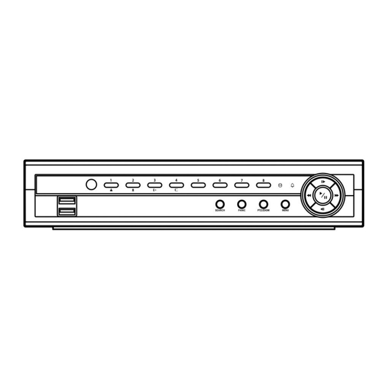
4- & 8-Channel Digital Video Recorder Chapter 3 Configuration NOTE: Your DVR should be completely installed before proceeding. Refer to Chapter 2 Installation. Front Panel Controls Figure 3 8-Channel DVR front panel. Camera Buttons HDD LED Alarm Out LED Arrow Buttons Play/Pause Button Menu Button PTZ/Zoom Button... -
Page 16: Hdd Led
User’s Manual HDD LED The HDD LED flickers when the DVR is recording or searching video on the hard disk drive. Alarm LED The Alarm LED is lit when alarm output or internal buzzer is activated. Arrow Buttons These buttons are used to navigate through menus and GUI. You can also use them to change numbers by highlighting a number in the menu and using the Up and Down arrow buttons to increase or decrease the number’s value. -
Page 17: Panic Button
4- & 8-Channel Digital Video Recorder In the live monitoring mode, pressing and holding the button for three seconds or PTZ/ZOOM longer enters the PTZ mode, and pressing and holding the button again for three seconds or longer exits the PTZ mode. When in the PTZ mode, pressing the arrow buttons or button allows MENU you to control properly configured cameras. -
Page 18: Remote Control Buttons
User’s Manual Remote Control Buttons ID Button Camera Buttons Sequence Button Freeze Button Arrow Buttons Menu Button Playback Buttons Panic Button Layout Button Zoom Button PTZ Button Enter Button Alarm Button PTZ Control Buttons Back Up Button Calendar Button Figure 4 Infrared remote control. -
Page 19: Arrow Buttons
4- & 8-Channel Digital Video Recorder Arrow Buttons These buttons are used to navigate through menus and GUI. You can also use them to change numbers by highlighting a number in the menu and using the Up and Down arrow buttons to increase or decrease the number’s value. -
Page 20: Ptz Button
User’s Manual PTZ Button Pressing the button enters the PTZ (Pan/Tilt/Zoom) mode which allows you to control properly configured cameras. Enter Button (Enter) button selects a highlighted item or completes an entry that you have made during system setup. This button is also used to enter the Cameo mode in the Live Monitoring mode or Search mode (8-ch Model Only). -
Page 21: Setup Screen
4- & 8-Channel Digital Video Recorder Press the button or move the mouse pointer to the top of the screen and then select (Login) MENU in the Live Monitoring menu to enter the setup screens. The Login screen appears. Select a User and enter the password by pressing the appropriate combination of Camera number buttons and then the button. -
Page 22: System Setup
User’s Manual Use the arrow keys to highlight the character you want in the name or title and press the button. That character appears in the title bar and the cursor moves to the next position. Pressing toggles between the upper and lower case keyboards, backspaces, and deletes entered characters. - Page 23 4- & 8-Channel Digital Video Recorder Highlight the box beside Language and press button. A drop-down menu displays the available languages. Highlight the desired language and press the button. The box beside Version displays the software version of the DVR. To upgrade the software, connect a USB device containing the upgrade package file to the DVR.
-
Page 24: Date/Time
User’s Manual The System Log screen lists system activities (up to 5,000 from the latest) that have occurred along with the time and date. The icon will be displayed in the last column for system activities of the remote site. You can scroll through the log pages by using the Up and Down arrows, or you can go directly to a log page by entering the log page number in the box at the bottom left of... -
Page 25: Figure 11 Holiday Setup Screen
4- & 8-Channel Digital Video Recorder Highlight the first box beside Time and press the button. The individual sections of the time will highlight. Use the Up and Down arrow buttons to change the number. Use the Left and Right arrow buttons to move between hour, minutes and seconds. -
Page 26: Storage
User’s Manual Highlight the box beside Interval and press the button. Set the time interval for synchronization from 30 minutes to 1 day at various time intervals. Last Sync-Time displays the last time the DVR was synchronized with the time server. Highlight Run as Server and press the button. -
Page 27: User
4- & 8-Channel Digital Video Recorder The Type column displays the type of storage device. The Disk Bad column displays the percentage of bad sectors. Not formatted – The device is not formatted. Good – Less than user-defined percentage of bad disk sections is damaged. - Page 28 User’s Manual Highlighting a Group Name and pressing the button allows you to change the authority levels assigned to the group. CAUTION: Write down the new password and save it in a secure place. If the password is forgotten, the unit must be reset using the Factory Reset Button and all data settings will be lost.
-
Page 29: Wizard
4- & 8-Channel Digital Video Recorder y Covert Camera Setup – The user can establish all Covert Camera settings on a local system or a PC running RAS. y Record Setup – The user can establish all Record settings on a local system or a PC running RAS. To add a User, highlight the + User…... -
Page 30: Figure 17 Quick Setup Wizard Screen
User’s Manual If you selected the Quick wizard, selecting the Next button starts the Quick Setup Wizard. Figure 17 Quick Setup Wizard screen. Date/Time Setup Date: Set the system date and select the date format. Time: Set the system time and select the time format. -
Page 31: Figure 18 Network Setup Wizard Screen
4- & 8-Channel Digital Video Recorder NOTE: The recording resolution will be set to Very High when selecting High Video Quality Priority Profile, High when selecting Standard Recording Profile, and Standard when selecting Longer Recording Time Priority Profile. NOTE: The recording quality and recording speed of each camera channel will be set as shown below according to the Record Method and Record Video Quality you set. - Page 32 User’s Manual LAN Setup Select between Auto Configuration and Manual Configuration for network configuration, and then select the Test button to test the network configuration you selected. NOTE: Selecting Auto Configuration allows the DVR to automatically obtain LAN parameters (IP address, Gateway, Subnet Mask and DNS Server address).
-
Page 33: Shutdown
4- & 8-Channel Digital Video Recorder Shutdown Highlight Shutdown in the System menu and press the button. The Shutdown screen displays asking you to confirm whether or not you want to shut the system down. After selecting Shutdown and pressing the button, a screen will appear telling you when it is safe to disconnect power. -
Page 34: Figure 22 Lan (Manual) Setup Screen
User’s Manual NOTE: Depending on network conditions, audio might be interrupted or out of synchronization during transmission. NOTE: Recorded audio might NOT be played properly on a PC running RAS when the DVR is connected to more than two RAS search programs at the same time. You can limit the network bandwidth settings so that system does not consume too much network bandwidth. - Page 35 4- & 8-Channel Digital Video Recorder NOTE: For the UPnP service to work, the NAT device should support the UPnP Port Forwarding function and the function should be set to enabled. NOTE: You cannot change the port settings when Use UPnP is On. Highlight the Status box and press the button to display the port numbers forwarded from the NAT device via UPnP service.
-
Page 36: Figure 23 Dvrns Setup Screen
User’s Manual NOTE: Entering the ID and Password and highlighting OK reads the current IP address of the DVR configured by the ADSL network. NOTE: If the DVR is configured for DHCP or an ADSL network, the IP address of the DVR might change whenever the unit is turned on. -
Page 37: Figure 24 Rtsp Setup Screen
4- & 8-Channel Digital Video Recorder Highlight the RTSP tab, and the RTSP setup screen displays. Highlight Enable RTSP (Real-Time Streaming Protocol) and press the button to toggle between On and Off. You will be able to change the settings if Enable RTSP is enabled. -
Page 38: Notification
User’s Manual Highlight Enable WebGuard Service and press the button to toggle between On and Off. See Appendix – WebGuard for detailed descriptions of the WebGuard service. Highlight the box beside Port and press the button. Set the port number used when accessing WebGuard by using the Up and Down arrow buttons to increase or decrease the numbers. -
Page 39: Devices Setup
4- & 8-Channel Digital Video Recorder Highlight the box beside Authentication and press the button. An Authentication screen appears. Highlight Use and press the button to toggle between On and Off. Highlight the box beside User/Password and press the button. A virtual keyboard appears allowing you to enter the user ID and password. -
Page 40: Figure 29 Camera Setup Screen
User’s Manual You can turn the camera number On or Off, and you can change the Title of each camera using the virtual keyboard. You can also determine which cameras will display on the monitors by selecting Normal, Covert 1 or Covert 2 from a drop-down list in the Use column. -
Page 41: Audio
4- & 8-Channel Digital Video Recorder Configure the port’s setting based on the PTZ camera manufacturer’s instructions. Audio Highlight Audio in the Devices menu and press the button. The Audio setup screen appears. The DVR can record up to four audio inputs. Highlight the box beside the input and press the button. -
Page 42: Display
User’s Manual You can add and edit alarm output schedules on this screen. Highlight the + and press the button to add a schedule. Highlighting the boxes under the Column heading and pressing button allows you to edit the information in those boxes. -
Page 43: Figure 35 Main Monitor Setup Screen
4- & 8-Channel Digital Video Recorder y Screen Group – The number of screen group displays when the DVR is not in the 3x3 and 1+7 modes of the 8-channel DVR, and 2x2 mode for the 4-channel DVR. y Free Space – The icon displays when the DVR is in the Recycle mode, and the percentage of available storage space displays when the DVR is not in the Recycle mode. -
Page 44: Remote Control
User’s Manual NOTE: Sequence cannot be used in the 3x3 and 1+7 modes of the 8-channel DVR, and 2x2 mode of the 4-channel DVR. You can adjust the display dwell time by highlighting the box beside Interval and pressing the button. -
Page 45: Recording Setup
4- & 8-Channel Digital Video Recorder Recording Setup Figure 38 Record menu. Record Highlight Record in the Record menu and press the button. The Record setup screen appears. Highlighting Recycle and pressing the button toggles between On and Off. In the Recycle mode, the DVR records over the oldest video data once all available storage space has been used. -
Page 46: Schedule
User’s Manual Highlight the box beside Auto Deletion, and use the Left and Right arrow buttons to adjust the length of time recorded data will be kept from 1 to 999 days. The DVR automatically deletes video recorded earlier than the user-defined period under three conditions: at midnight, whenever the system reboots or whenever the user changes the Auto Deletion settings. -
Page 47: Figure 41 Schedule Setup Screen
4- & 8-Channel Digital Video Recorder < Simple Mode > < Advanced Mode > Figure 41 Schedule setup screen. You can program the DVR to record only during certain times based on time, day of the week, and holidays. The smallest time segment you can use is 15 minutes. Highlighting Schedule On and pressing the button toggles between On and Off. -
Page 48: Figure 42 Schedule - Settings (Advanced Mode) Setup Screen
User’s Manual When the DVR is in the Time & Event mode, the DVR will follow the Time settings and the icon displays. The DVR follows the Event settings and the icon displays. Highlight the box under the Channels heading and press the button to select which cameras will be recorded. -
Page 49: Pre-Event
4- & 8-Channel Digital Video Recorder -Event Highlight Pre-Event in the Record menu and press the button, and the Pre-Event setup screen appears. If you do not have Event set up in the Record Schedule, a message will display alerting you to this fact. -
Page 50: Figure 45 Alarm-In Settings Setup Screen
User’s Manual The alarm terminal strip on the back of the DVR has inputs associated with each alarm. You can set up each input on the Alarm-In screen. You can turn each input On or Off by highlighting the alarm number and pressing the button. -
Page 51: Motion Detection
4- & 8-Channel Digital Video Recorder You can toggle the entire list On and Off by highlighting Notification and pressing the button. You can toggle the individual items On and Off by highlighting that item and pressing the button. Highlight OK and press the button to accept your changes. - Page 52 User’s Manual The Motion Detection Zone screen is laid over the video for the selected camera. You can set up motion detection zones by selecting or clearing blocks. NOTE: You can set up motion zones one block at a time in groups of three or six individual block groups (4- and 8-channel DVR respectively).
-
Page 53: Video Loss
4- & 8-Channel Digital Video Recorder The DVR can be set to react to motion detection differently for each camera. Each camera can be associated with another camera, trigger an Alarm-Out connector, sound the DVR’s internal buzzer, notify a number of different devices, and/or move PTZ cameras to preset positions. -
Page 54: Figure 49 Video Loss Settings Setup Screen
User’s Manual Highlighting the box under the Video Loss Interval heading allows you to set the duration of a signal loss before the DVR will report a Video Loss. The DVR will not consider any signal loss from a camera to be a Video Loss if the detected signal loss is shorter than the interval set on this screen. -
Page 55: Video Blind
4- & 8-Channel Digital Video Recorder Video Blind Highlight Video Blind in the Event menu and press the button. The Video Blind setup screen appears. The DVR checks to see if anything is blinding the camera. Highlighting the box under the Sensitivity heading allows you to adjust the DVR’s sensitivity to video blind from 1 (least sensitive) to 15 (most sensitive). -
Page 56: Text-In
User’s Manual NOTE: For the Alarm-Out action, the alarm output and beep you select should be set to the Event mode in the Alarm-Out setup screen (Schedule tab). Highlight the box under the Notify heading and press the button. You can toggle the entire list On and Off by highlighting Notification and pressing the button. - Page 57 4- & 8-Channel Digital Video Recorder NOTE: The following description is for a Generic Text Device. The screen changes for different types of text input devices, and there will be different parameter boxes for you to enter information. Highlight the box beside Transaction Start, and press the button.
-
Page 58: System Event
User’s Manual The DVR can be set to react to text input. Text input can be associated with cameras, trigger an Alarm-Out connector, sound the DVR’s internal buzzer, notify a number of different devices, and/or move PTZ cameras to preset positions. Highlight the box beside Record and press the button. -
Page 59: Figure 56 Health Check Setup Screen
4- & 8-Channel Digital Video Recorder The DVR can be configured to run self- diagnostics and report the results. Highlighting the box beside System and pressing the button allows you to select the interval that you want the DVR to run self- diagnostics on the system. -
Page 60: Event Status
User’s Manual Highlight the second box beside Disk S.M.A.R.T., and press the button. Select either ºC (Celsius) or ºF (Fahrenheit), and press the button. Highlight the Actions tab and the System Event Actions setup screen displays. The DVR can be set to react to system events. System events can activate the Alarm-Out connector, sound the DVR’s internal buzzer, and/or notify a number of different devices. -
Page 61: Figure 59 Event Status Setup Screen
4- & 8-Channel Digital Video Recorder The Event Status screen displays the status of the DVR’s systems and inputs. Events will be highlighted, and related channels or events will flicker for five seconds when detected. Alarm-In, Motion, Video Loss, Video Blind and Text-In will be highlighted when each event is detected based on the settings you made in the Alarm-In, Motion Detection, Video Loss, Video... - Page 62 User’s Manual...
-
Page 63: Chapter 4 Operation
4- & 8-Channel Digital Video Recorder Chapter 4 Operation NOTE: This chapter assumes your DVR has been installed and configured. If it has not, please refer to Chapters 2 and 3. The DVR’s controls are similar to a VCR. As with a VCR, the main functions are recording and playing back video. -
Page 64: Live Monitoring Menu
User’s Manual Live Monitoring Menu Freeze Selecting (Freeze) in the Live Monitoring menu will freeze the current image on the screen until you select again. It is the same as pressing the (Play/Pause) button on the front panel. While in the Freeze mode, the icon displays in bottom-left corner if Freeze is selected in the Display setup screen (OSD tab). -
Page 65: Active Cameo Mode
4- & 8-Channel Digital Video Recorder NOTE: Any image adjustments you make will be applied to both the live video on the monitors and the recorded video. NOTE: The Camera Menu also can be displayed by clicking the right mouse button on the screen while in the live monitoring mode. -
Page 66: Zoom Mode
User’s Manual In active cameo mode, press the button for the camera you want to display in the active cameo. After setting the camera number to active cameo, the DVR moves the active cameo to the next cameo. When the camera number exists on the current screen, the active cameo is changed with the existing camera number. -
Page 67: Ptz Mode
4- & 8-Channel Digital Video Recorder PTZ Mode If a user who has PTZ Control authority logs into the system, the user can control PTZ cameras. The DVR will control cameras with Pan, Tilt and Zoom capabilities. Select PTZ from the Camera Menu in the Live Monitoring menu or press and hold the button on the front panel for three seconds or longer to display the PTZ camera menu and enter the PTZ mode. -
Page 68: Using A Mouse
User’s Manual Clicking on the left side exits the toolbar. If you want to display the toolbar again, position the mouse pointer at the bottom of the screen. Change the toolbar location by clicking the empty space on the left side of the toolbar and drag it to where you want it located on the screen. -
Page 69: Recording Video
4- & 8-Channel Digital Video Recorder NOTE: In the 1+5 or 1+7 display mode, the main channel indicates the channel displayed on the large screen which is displayed in the top-left. You can select the camera you want to display on the main channel screen. Select a channel on the screen and click the right mouse button to display the Camera Menu. -
Page 70: Recording Audio
User’s Manual Although you will be able to record without changing the unit from its original factory settings, you will want to take advantages of the DVR’s many tools. See Chapter 3 Configuration for detailed descriptions of the recording mode options. Recording Audio If the DVR was set up to record audio, it will record audio from up to four inputs when video is recording. -
Page 71: Searching Video
4- & 8-Channel Digital Video Recorder Go to the previous image Play/Pause Go to the next image Fast backward play Fast forward play Searching Video While in the search mode, pressing the button displays the following Search menu at the MENU top of the screen. - Page 72 User’s Manual Move the cursor over the date and time and press the (Play/Pause) button. You can use the Left and Right arrow buttons to highlight the year, month, day, hours, minutes and seconds. Use the Up and Down arrow buttons to change to the date and time you want to search for video. button.
-
Page 73: Event Log Search
4- & 8-Channel Digital Video Recorder Alarm Selecting (Alarm) in the Search menu resets the DVR’s outputs including the internal buzzer during an alarm. It is the same as pressing any button on the front panel when the alarm is activated. Panic Selecting (Panic) in the Search menu starts panic recording of all cameras, and selecting... - Page 74 User’s Manual You can search video from the first to last recorded images, or you can set the start and stop times and dates. Highlight the box beside From and press the button to toggle between On and Off. When set to Off, you can enter a specific Date and Time.
-
Page 75: Record Table Search
4- & 8-Channel Digital Video Recorder Once you set your desired search conditions, highlight Search and press the button to display the search results in the Event Log Search screen. Selecting Cancel exits the screen without saving the changes. Record Table Search Recording information about video images currently displayed on the screen displays on the <... -
Page 76: Motion Search
User’s Manual Days with recorded video display on the calendar with white numbers. You can highlight the days with recorded video by using the arrow buttons. Once you have highlighted a day, press the (Play/Pause) button to select it. The first recorded image of the selected date will pause on the screen. - Page 77 4- & 8-Channel Digital Video Recorder You can search video from the first to last recorded images, or you can set the start and stop times and dates. Highlight the box beside From and press the button to toggle between On and Off. When set to Off, you can enter a specific Date and Time.
-
Page 78: Text-In Search
User’s Manual Text-In Search The DVR maintains a log of each time there is Text Input. The Text-In Search screen displays this list. Use the arrow buttons to highlight the event for which you would like to see video. Pressing the (Play/Pause) button will extract the video associated with the Text Input and display the first image of the event. -
Page 79: Clip-Copy
4- & 8-Channel Digital Video Recorder Highlighting the + and pressing the button allows you to add a new set of search parameter. Set up the desired search parameter. Refer to the Appendix – Text-In Search Examples for further information on setting up search parameters. The column can be used to delete a set of search parameter or entire sets of search parameters. - Page 80 User’s Manual Highlight the box beside Password and press the button. A virtual keyboard appears allowing you to enter the password for reviewing the video clips. Highlight the box beside Dest. and press the button. You can select the storage device on which you would like to record the video clip.
-
Page 81: Appendix
4- & 8-Channel Digital Video Recorder Appendix USB Hard Disk Drive Preparation Preparing the USB hard disk drive in Windows 2000 NOTE: Preparing a USB hard disk drive under Windows XP, Windows Vista and Windows 7 is almost identical to Windows 2000. 1. -
Page 82: Text-In Search Examples
User’s Manual 12. Right click the newly created hard disk drive icon and select “Format”. 13. In the Format Screen, select “Full” as the “Format type” and click “Start”. 14. After formatting is complete, connect the USB hard disk drive to the DVR. Text-In Search Examples Search Example I 123456789012345678901234567890123456789012345678901234567890... -
Page 83: Search Example Ii
4- & 8-Channel Digital Video Recorder Search Example II 123456789012345678901234567890123456789012345678901234567890 Item Unit price amount ================================================== Coke 2.20 | 1(s) 2.20 Fanta 2.20 | 1(s) 2.20 Hotdog 3.50 | 3(s) 10.50 Pepsi 1.95 | 1(s) 1.95 ================================================== total : $ 16.85 Thank you~~ In the above text-in data, you can find that the comparison value is located at 17 (Unit price, $ mark... - Page 84 User’s Manual Computer system requirements for using the WebGuard program are: ® ® ® Operating System: Microsoft Windows XP x86 (32 Bit) (Service Pack 3), Microsoft ® ® ® Windows Vista x86 (32 Bit) (Service Pack 1), Microsoft Windows 7 x86 (32 Bit) CPU: Intel Pentium III (Celeron) 600MHz or faster RAM: 128MB or higher VGA: 8MB or higher (1024x768, 24bpp or higher)
-
Page 85: Web Monitoring Mode
4- & 8-Channel Digital Video Recorder NOTE: When running WebGuard in the Microsoft Windows Vista or higher operating system, it is recommended to start Internet Explorer with elevated administrator permissions. Click the right mouse button on the Internet Explorer icon and select the Run as administrator option from the context menu. -
Page 86: Web Search Mode
User’s Manual Click the camera button to select the camera to be viewed. Click the to adjust the brightness, contrast, saturation and hue of monitoring image. Click the to control pan, tilt and zoom of the camera from a remote site. Click the to control alarm out devices at the remote site. - Page 87 4- & 8-Channel Digital Video Recorder Click the to log out the WebGuard program. Click the to access to the web monitoring mode. Position the mouse pointer on the WebSearch logo to see the version of the WebGuard program. The DVR information window displays the time information of recorded data on the remote DVR and login information of WebGuard.
-
Page 88: System Log Notices
User’s Manual Click the to save any video clip of recorded data as an executable file, or click the to save the current image in a bitmap or JPEG file format. Click the to print the current image on a printer connected to your computer. Click the to reload the recording data. -
Page 89: Error Code Notices
4- & 8-Channel Digital Video Recorder Error Code Notices System Upgrade Related Clip Copy Related Description Description Unknown error. Unknown error. File version error. Device error. Operating system version error. Mounting failed. Software version error. No media. Kernel version error. Invalid media. -
Page 90: Map Of Screens
User’s Manual Map of Screens... -
Page 91: Specifications
4- & 8-Channel Digital Video Recorder Specifications VIDEO Signal Format NTSC or PAL (Auto Detect) Video Input Composite: 4 or 8 inputs, 1 Vp-p, auto-terminating, 75 Ohms Composite: 1 BNC, 1 Vp-p, 75 Ohms Monitor Outputs VGA: 1 (Auto Detect) Composite: 720x480 (NTSC), 720x576 (PAL) Video Resolution VGA: 800x600, 1024x768, 1280x1024@60Hz... - Page 92 User’s Manual GENERAL Dimensions (W x H x D) 10.4" x 2.0" x 7.5" (265mm x 52mm x 191mm) Unit Weight 3.7 lbs. (1.7kg) Shipping Weight 7.3 lbs. (3.3kg) Shipping Dimensions 14.2" x 4.3" x 18.1" (360mm x 110mm x 460mm) (W x H x D) Operating Temperature 41°F to 104°F (5°C to 40°C) Operating Humidity...
Need help?
Do you have a question about the E-DVR-104 and is the answer not in the manual?
Questions and answers