Advertisement
Table of Contents
- 1 Table of Contents
- 2 Important Safety Instructions
- 3 Grid Connection
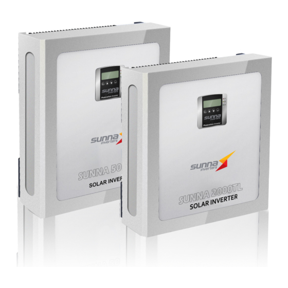
- 4 Product Overview
- 5 Unit Description
- 6 Installation
- 7 Front Panel Functional Descriptions
- 8 Starting the SUNNA Series Inverter
- 9 The Communications Interface
- 10 Inverter Status Diagnostics and Repair
- 11 Specifications
- Download this manual
Advertisement
Table of Contents

Summary of Contents for Sunna Inverters SUNNA 1500TL
- Page 1 SUNNA SERIES PHOTOVOLTAIC INVERTER USER MANUAL SUNNA 1500TL / 2000TL / 3000TL / 4200TL / 5000TL...
-
Page 2: Table Of Contents
Contents Introduction..........................2 Important Safety Instructions....................4 Product Overview........................5 Installation..........................10 Front Panel Functional Descriptions................16 Starting the SUNNA Series Inverter..................17 The Communications Interface..................23 Inverter Status Diagnostics and Repair................26 Specifications...........................30 Introduction Thank you for buying this SUNNA Series Inverter. Many years of design experience has gone into the construction of this device, and your SUNNA Series Inverter should give your solar power system many years of trouble-free operation. -
Page 3: Important Safety Instructions
Important Safety Instructions General Warning! Incorrect operation and/or work performed can cause serious injury and damage! Only qualified personnel are authorised to install your SUNNA Series Inverter; installation should be carried out within the scope of the respective technical regulations. Do not start operation or carry out maintenance work before reading the chapter ‘Important Safety Instructions’. -
Page 4: Grid Connection
PV Module Before connecting the solar modules, you must check whether the voltage parameters specified in the manufacturer’s data correspond with the actual parameters. When checking the voltage reading, please take into account that solar modules supply a higher no-load voltage when temperature is low and sunlight level remains unchanged. -
Page 5: Product Overview
Product Overview External Dimensions Module number SUNNA 1500TL, SUNNA 4200TL, Dimensions (mm) 2000TL, 5000TL 3000TL... -
Page 6: Unit Description
1. LCD & LED Display: Shows the operation information and status of the inverter. 2. Solar Array Input: Plug-and-play connector terminals for the connection of the solar modules (The SUNNA 1500TL/2000TL/SR3000TL only have one PV string input). 3. Standard Communication Port : EPO & RS232. -
Page 7: Installation
Remove the SUNNA Inverter from its box. Check the package contents. Standard contents should include: ✓ 1 set of accessories ✓ 1 data CD-ROM ✓ 1 Mounting Frame Accessory Kit (shown below): SUNNA 4200TL/5000TL SUNNA 1500TL/2000TL/3000TL... -
Page 8: Installation Requirements
Installation Requirements The SUNNA Series Inverter is heavy. Take this weight into consideration when choosing the installation site and method of installation. To ensure proper operation and long operating life, always position the SUNNA Series Inverter according to the following requirements: SUNNA1500TL/2000TL/3000TL 23Kg SUNNA 4200TL/5000TL 28Kg (1) The SUNNA Series Inverter is designed... -
Page 9: Mounting The Unit
(3) When choosing the installation site, ensure there is enough space for heat dissipation. Under normal conditions, installers should adhere to the following guidelines regarding space to be left clear around the inverter: Mounting the Unit We recommend that you use the supplied wall mounting bracket to mount the SUNNA Series Inverter. - Page 10 Installation: Step by Step Step 1. Fit the wall mounting bracket. When marking the positions of the drill holes, use the wall mounting bracket as a drilling template. Step 2. Hang the SUNNA Series Inverter onto the wall mounting bracket using its upper mounting plate.
-
Page 11: Electrical Installation
Electrical Installation The correct installation for the SUNNA Series Inverter is shown in the following diagram below (Fig. 1) Fig. 1... - Page 12 Connecting to the Grid (AC utility) To connect the AC cable, proceed as follows: Step 1. Measure the voltage and frequency of the Grid/Utility. The voltage and frequency of the Grid/Utility will differ between countries. Step 2. Before wiring the SUNNA Series Inverter, ensure the main breaker in the primary utility breaker box is switched to OFF.
- Page 13 To prevent risk of electric shock, ensure the Earth wire is properly Earthed before operating the SUNNA Series Inverter. Suggested cable width for AC wire; Model Diameter (mm) Area (mm AWG no. SUNNA >2.59 >5.5 >10 4200TL/5000TL SUNNA 1500TL/ >2.05 >3.5 >12 2000TL/ 3000TL...
- Page 14 PV Module Requirements The SUNNA Series Inverters are designed with input connector terminals for the connection of solar modules. Models SUNNA 1500TL/2000TL/3000TL have one connector terminal, Models SUNNA 4200TL/5000TL have two connector terminals. Each connector terminal can be connected to a string of PV modules.
- Page 15 GUIDELINES: When determining the number of panels required in a PV string, ensure the following three requirements are met: 1. To avoid damage to the SUNNA Series Inverter, make sure the maximum open circuit voltage (Voc) of each PV string is less than 500 Vdc under any condition.
-
Page 16: Front Panel Functional Descriptions
Front Panel Functional Descriptions Symbols on the LCD Display Pane LCD Display Symbol Description Utility Source Inverter working in specified mode Solar Cell Inverter operation mode Flow Chart 4 Digits Measurement Display LED Indicators RED LED steadily lights up to indicate an Earth fault or a DC input isolation fault. -
Page 17: Starting The Sunna Series Inverter
Starting the SUNNA Series Inverter Before the inverter is started, check the following: The housing cover is securely screwed tight. The AC breaker is OFF. The DC cables (PV strings) are fully connected. The AC (utility) cable is connected correctly. Operation Test and Installation Instruction Connect the PV string voltage by switching on the DC circuit breaker. - Page 18 Turn on the AC breaker. If Utility specification (ex. voltage, frequency etc.) is matched with the specs of the inverter, after 300 seconds the LCD display will illustrate drawing C. And the Yellow LED will go out to indicate that the utility is acceptable by the inverter.
- Page 19 If start-up operation of the inverter is complete and successful. The LCD display will illustrate drawing E. Checking Measured Values & Figures If you would like to check the measured values and figures detected by the Inverter, please scroll up and scroll down using the key pad. When scrolling down using the key pad, the LCD display will illustrate as follows: Input DC Voltage of String A, as drawing G.
- Page 20 Output Power of Booster A, as drawing K. Output Power of Booster B, as drawing L. Output Voltage of Inverter (Utility Voltage), as drawing M. Output Frequency of Inverter (Utility Frequency), as drawing N. Output Current Supplied to Load, as drawing O.
- Page 21 Output Power Supplied to Load, as drawing P. Energy KWH Supplied to Load, as drawing Q. Inverter Inner Temperature (°C, °F) , as drawing R. Heat Sink Temperature (°C, °F) , as drawing S.
- Page 22 SUNNA Series Inverter Status Descriptions The SUNNA Series Inverter starts up automatically when DC-power from the PV panel is sufficient. Once the inverter starts, it enters into one of the following status: Operation LCD panel display Description mode Normal In this mode, the SUNNA Series Inverter works normally.
-
Page 23: The Communications Interface
The Communications Interface Standard communications interface RS232 interface definition The RS232 interface shall be set as follows: Baud Rate 9600 bps Data Length 8 bits Stop Bit 1 bit Parity None The Pin Assignments of true RS232 type. The pin assignments of true RS232 type are illustrated as follows: Pin 2: RS232 Rx Pin 3: RS232 Tx... - Page 24 RS-485 card CN1 is for the function of the terminal resistor. Short Pin 1-2 to enable the function and short Pin 2-3 to disable it. CN2 is RS485 terminal definition 1 → Earth 2 → A/Data+ 3 → B/Data- USB card CN2 for USB.
- Page 25 True Relay Contact Board (DCE-B card) The pin assignments of 10-Pin Terminal: Pin 1: Voltage of utility is abnormal. Pin 2: PV strings voltage is normal. Pin 3: PV strings voltage is abnormal. Pin 4: Frequency of utility is abnormal. Pin 5: Anti-islanding.
-
Page 26: Inverter Status Diagnostics And Repair
Inverter Status Diagnostics and Repair The SUNNA Series Inverter is equipped with an on-board self diagnostic system. This system can automatically identify a large number of possible operational issues and provide notification via its LCD screen. This system makes it possible to quickly isolate technical issues, and to distinguish between Service Codes related to the installation versus Service Codes which are internal to the inverter. - Page 27 Designation Description Repair indicate Er06 Inverter enters into 1. Remove the short circuit EPO mode (Emerge occurred at the EPO terminal. Power Off). 2. If error code keeps recurring, contact your local distributor. Er09 Inverter Output Over-current on the 1. Turn off AC breaker, and over-current AC side.
- Page 28 Table 3. Grid Fault Alarm Code and Alarm Code Description Designation Description Repair indicate AL00 Utility Voltage Utility Voltage 1. Wait for 1 minute, if the grid Over-Voltage greater or returns to normal, the inverter smaller than the will automatically restart. permissible value.
- Page 29 Designation Description Repair indicate AL09 Inverter Voltage Inverter Voltage 1. Shut down inverter (unplug PV unbalance Waveform is in generator from the input). unbalance. 2. Check grid usability and restart inverter (plug PV generator from the input). 3. If error code keeps recurring, contact your local distributor for help.
-
Page 30: Specifications
Specifications SUNNA SUNNA SUNNA SUNNA SUNNA Unit Model 1500TL 2000TL 3000TL 4200TL 5000TL Conversion Mode Sine-wave, Current source, High frequency PWM Inverter Technology Isolation Method Transformer-less Design* DC Input Data Nominal DC Voltage 360 VDC Maximum DC Input Voltage 500 VDC Work Range 120VDC~500VDC** Maximum DC Input Current... - Page 31 SUNNA SUNNA SUNNA SUNNA SUNNA Unit Model 1500TL 2000TL 3000TL 4200TL 5000TL Communication Standard RS232 Communication Interface Optional USB, RS485, dry contact, TCP/IP Front Panel Boost input Voltage/Boost input Current/Boost input Power/AC output Voltage /AC output frequency/AC output current /AC output power/AC Energy yield/Inner Temperature/Heat sink Temperature /Status message/ Error message Leakage current fault or DC input isolation fault Yellow...
Need help?
Do you have a question about the SUNNA 1500TL and is the answer not in the manual?
Questions and answers