
Related Manuals for CAMBRIDGE Qt 100


Summary of Contents for CAMBRIDGE Qt 100
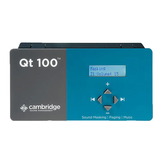
- Page 1 I N S T A L L A T I O N A N D O P E R A T I O N S G U I D E Qt 100 ™ www.csmqt.com 800.219.8199 S O U N D M A S K I N G...
-
Page 2: Table Of Contents
Contents Qt 100 Introduction Hardware Installation Installing the Control Module Wall Mount (back panel of the controller) Connections to the Front Panel Connect Paging or Music Contact Closure Connecting Power Installing Qt Emitters Emitter Installation Order Custom Cabling Guidelines System Configuration via the Front Panel... -
Page 3: Qt 100 Introduction
It is important that the masking volume be set correctly to achieve the full effectiveness of the Qt 100 system. If volume levels are set too low, speech privacy will be reduced and workplace distractions will become more apparent. -
Page 4: Hardware Installation
OTHERWISE: If a sound level meter is not available, the recommended levels are likely to be achieved in most environments by setting the control module’s masking volumes as follows: Control Module’s Masking Volume Settings Private Office Zones 05-09, for all ceiling heights Open Area Zones 13-16, for 08 ft. -
Page 5: Connections To The Front Panel
GND. Contact Closure The Qt 100 provides an instant shut-off capability for masking if connected to a contact closure interface. The contact closure utilizes the same connector as the audio input. To leverage this feature, connect a two-conductor cable to the two connectors, labeled “contact”. -
Page 6: Connecting Power
Connecting Power The controller comes standard with a 24 V wall plug power supply. This supply features a wall plug and a fixed barrel connector. Alternatively, power can be supplied to the fixed block connector, which allows for stripped and tinned wires for added flexibility and convenience. -
Page 7: Installing Qt Emitters
Installing Qt Emitters Important Considerations: • Each run has a maximum of 60 emitters! • Each run supports a maximum cable length of 1000 ft. • Each home run cable attached to the control module should be labeled by Zone # and Run #. Adding a logical name (e.g. Marketing, Private Offices) is suggested. - Page 8 Connect a run cable from Connect the next OUTPUT the specified OUTPUT jack cable to the emitter OUTPUT on the module to the INPUT jack. jack of the first emitter. Run the cable to next Listen to each emitter as it is designated tile specified on connected.
-
Page 9: Custom Cabling Guidelines
Custom Cabling Guidelines For system compliance, follow these guidelines if custom cables are required: Use solid conductor 24 AWG CAT cable that meets local code requirements. If the system is installed in a return air plenum, the cable must be plenum rated. -
Page 10: System Configuration Via The Front Panel
System Configuration via the Front Panel After the Qt 100 is mounted and the emitters have been tested, it is time to configure the Qt 100 for general operation. The front panel display shows system information and allows for adjustment of the masking and the auxiliary audio input levels. -
Page 11: Setting Sound Masking Level
Setting Sound Masking Level Masking Z1 Volume: Mute This figure shows that the format of the panel for configuring masking. Z1 stands for zone 1 and it is currently set to mute. The initial value of Mute is displayed. To adjust the level, use the up and down arrows while this screen is displayed. -
Page 12: Error Codes
Error Codes and Clear Error System errors are shown on the control module front panel display. If an error occurs, the message “Status: Error” will be displayed. To determine the cause of the error, press NEXT (right arrow button), to display the error code. -
Page 13: Post Installation Handoff
Lock the control module panel by holding down the left and right buttons for 5 seconds. If you need assistance installing or commissioning this Qt 100 sound masking system, please contact CSM support at: 1.800.219.8199 (Toll free within US & Canada) 617.349.3779 (Outside US &... -
Page 14: Warranty
FCC rules. Warranty Coverage — Qt Emitters™ Cambridge Sound Management, LLC (the “warrantor”) will, for a period of five (5) years, starting with the date of purchase, warrant that the Qt Emitters™ (the “speakers”) will be free of defects in materials and workmanship that interfere with proper operation as a sound masking, paging and music speaker system. - Page 15 If the product is still not functioning properly after making use of these resources, please contact Cambridge Sound Management for a return authorization number. All returns are to be prepaid. The warrantor will pay return surface freight within the continental United States on warranty repairs.
- Page 16 Zone Destination Record Zone 1 Run 1 Run 2 Settings Record Volumes: Zone: Masking: Input A: Installation / Service: Company name: Install date: Phone: www.csmqt.com 800.219.8199...
Need help?
Do you have a question about the Qt 100 and is the answer not in the manual?
Questions and answers