Table of Contents
Advertisement
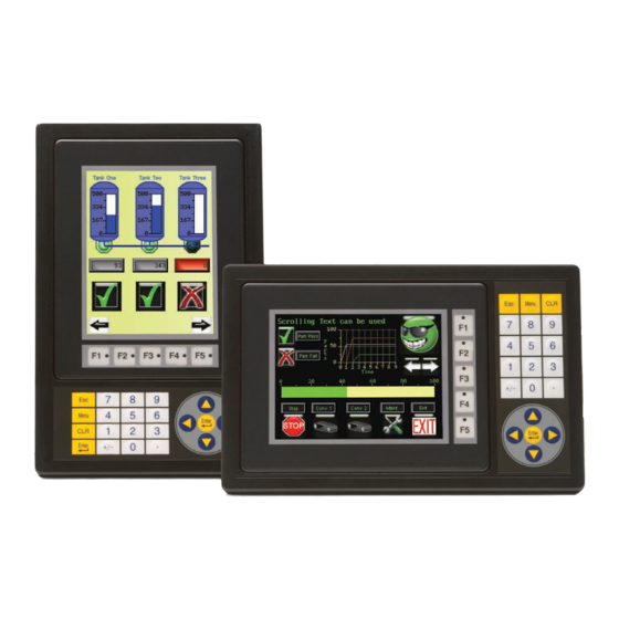
6-inch Color Micro-Graphic Panel
®
Hardware User Manual
EA1-TCL-M
C-more 6" Color Micro-Graphic Panel
shown in Portrait Mode
C-more 6" Color Micro-Graphic Panel
shown in Landscape Mode
C-more 6" Color Micro-Graphic Panel Installed in a
21-button Portrait Keypad Bezel EA-MG6-BZ2P
C-more 6" Color Micro-Graphic Panel Installed in a
20-button Landscape Keypad Bezel EA-MG6-BZ2
Advertisement
Table of Contents

Related Manuals for C-MORE EA1-TCL-M

Summary of Contents for C-MORE EA1-TCL-M
- Page 1 C-more 6” Color Micro-Graphic Panel shown in Portrait Mode C-more 6” Color Micro-Graphic Panel shown in Landscape Mode C-more 6” Color Micro-Graphic Panel Installed in a 21-button Portrait Keypad Bezel EA-MG6-BZ2P C-more 6” Color Micro-Graphic Panel Installed in a 20-button Landscape Keypad Bezel EA-MG6-BZ2...
- Page 3 Graphic Color Panel - 6 Inch EA1-T6CL HARDWARE USER MANUAL Please include the Manual Number and the Manual Issue, both shown below, when communicating with Technical Support regarding this publication. Manual Number: EA1-TCL-M Issue: 1st Edition Issue Date: 12/09 Publication History...
- Page 5 WARNING Thank you for purchasing automation equipment from Automationdirect.com ® , doing business as, AutomationDirect. We want your new automation equipment to operate safely. Anyone who installs or uses this equipment should read this publication (and any other relevant publications) before installing or operating the equipment.
- Page 6 ADVERTENCIA Gracias por comprar equipo de automatización de Automationdirect.com ® . Deseamos que su nuevo equipo de automatización opere de manera segura. Cualquier persona que instale o use este equipo debe leer esta publicación (y cualquier otra publicación pertinente) antes de instalar u operar el equipo. Para reducir al mínimo el riesgo debido a problemas de seguridad, debe seguir todos los códigos de seguridad locales o nacionales aplicables que regulan la instalación y operación de su equipo.
- Page 7 AVERTISSEMENT ® Nous vous remercions d'avoir acheté l'équipement d'automatisation de Automationdirect.com , en faisant des affaires comme, AutomationDirect. Nous tenons à ce que votre nouvel équipement d'automatisation fonctionne en toute sécurité. Toute personne qui installe ou utilise cet équipement doit lire la présente publication (et toutes les autres publications pertinentes) avant de l'installer ou de l'utiliser.
-
Page 9: Table Of Contents
Step 3 – Become Familiar with Available Communication Ports ....1–8 Step 4 – Install C-more 6” Color Micro-Graphic Panel ..... . .1–9 Enclosure Clearances . - Page 10 Accessories ............3–2 C-more Micro-Graphic Programming Software ......3–3 20-Button Landscape (Horizontal) Keypad Bezel .
- Page 11 Available PLC Protocols ..........6–3 C-more 6” Micro-Graphic Communication Ports ......6–4 DirectLOGIC PLCs Password Protection .
- Page 12 Panel & PLC Error Codes ..........8–8 C-more Micro-Graphic Panel Runtime Errors ......8–9 Reset to Factory Default .
- Page 13 Introduction ............A–2 C-more Micro-Graphic Panel Error Code Table ......A–3 Modbus Protocols Error Code P499 Explanation .
-
Page 15: In This Chapter
Step 3 – Become Familiar with Available Communication Ports ....1–8 Step 4 – Install C-more 6” Color Micro-Graphic Panel ..... . .1–9 Enclosure Clearances . -
Page 16: Chapter 1: Getting Started
Chapter 1: Getting Started Introduction The Purpose of this Manual Thank you for purchasing from our C-more ® Micro-Graphic family of products. This manual describes AutomationDirect.com’s C-more 6” Color Micro-Graphic panels, specifications, included components and available accessories and provides you with important information for installation, connectivity and setup. -
Page 17: Conventions Used
The beginning of each chapter will list the key topics that can be found in that chapter. HAPTER Getting Started In This Chapter... General Information ..............1-2 Spec fications ................1-4 1–3 ® EA1-TCL-M Hardware User Manual, 1st Ed., 12/09... -
Page 18: Product Overview
53 lines of static text and 40 lines by 40 characters of dynamic text. EA1-T6CL is rated UL for use on a flat surface of Type 1, 4X enclosure (for indoor use only). The C-more 6” Micro-Graphic panels are powered from a 12-24 VDC power supply during operation, or can be powered in low power mode thru the USB port from a PC during programming. -
Page 19: Part Number Key
L: LED EA1-T6CL Display Type: S: STN T: TFT Bezel Part Number Key The optional C-more 6” Micro-Graphic keypad bezel part numbers consist of the following: Series Name: EA MG6: C more 6” Micro Graphic Bezel Option Module EA-MG6-XXXX Module Type:... -
Page 20: Optional Accessories
Chapter 1: Getting Started Quick Start Steps Step 1 – Unpack and Inspect a.) Unpack the C-more 6” Color Micro-Graphic panel from its shipping carton. Included in the carton are the following: • C-more 6” Color Micro-Graphic panel (EA1-T6CL) • DC power connector (EA-MG-DC-CON) •... -
Page 21: Step 2 - Install Optional Hardware Accessories
Chapter 1: Getting Started Step 2 – Install Optional Hardware Accessories Below is an example of a C-more 6” Micro-Graphic panel being assembled with an optional EA-MG6-BZ2 20-button Keypad Bezel. 3. Use (8) Bezel Mounting Clips, 2. Use the (4) Panel Mounting... -
Page 22: Step 3 - Become Familiar With Available Communication Ports
Chapter 1: Getting Started Step 3 – Become Familiar with Available Communication Ports The C-more 6” Color Micro-Graphic panel includes a built-in USB Type B port used to communicate with a PC during project development. There is a 15-pin RS-232/RS-422/RS- 485 port for communications to a PLC. -
Page 23: Step 4 - Install C-More 6" Color Micro-Graphic Panel
Step 4 – Install C-more 6” Color Micro-Graphic Panel The C-more 6” Micro-Graphic panel can be mounted through a cutout in an enclosure by using the template that is provided with the panel, or using the dimensions shown below. Cutout dimensions for the 20-button landscape and 21-button portrait keypad bezel options are also shown below. -
Page 24: Enclosure Clearances
EA1-T6CL with EA-2CBL USB programming cable NOTE: Cable connectors are typically longer than 1.2” (30mm). Therefore, in addition to ventilation requirements, clearance must account for the connector and the cable bend radius. 1–10 ® EA1-TCL-M Hardware User Manual, 1st Ed., 12/09... -
Page 25: Step 5 – Install The Programming Software And Develop A Project
• Operating System - Windows® XP Home / Professional Edition Service Pack 2, Windows® 2000 with Service Pack 4, or Windows® Vista (32 bit) Insert the C-more Micro-Graphic Programming Software CD-ROM into the PC’s CD-ROM drive or download the programming software from www.automationdirect.com and follow the instructions. -
Page 26: Step 5 - Connect C-More 6" Color Micro-Graphic Panel To Computer
Use a programming cable such as USB-CBL-AB6 from a USB port type A on the project development PC to the USB port type B on the C-more 6” Color Micro Graphic Panel as shown below. Any standard Type A to Type B USB cable can be used such as a standard USB printer cable, maximum length 15’. - Page 27 Step 7 – Providing Power to the C-more 6” Color Micro-Graphic Panel Power can be supplied to the C-more Micro-Graphic panel in one of three different ways. 1). The panel is powered by a 1 Amp @ 12-24 VDC power source in normal operation.
-
Page 28: Step 7 - Accessing The C-More 6" Color Micro-Graphic Panel Setup Screens
Chapter 1: Getting Started Step 8 – Accessing the C-more 6” Color Micro-Graphic Panel Setup Screens To access the Setup Menu of the panel’s setup screens, press the the BAK [F1] and ENT [F5] function keys simultaneously for three (3) seconds. -
Page 29: Step 8 - Choose C-More 6" Color Micro-Graphic Panel To Plc Protocol & Cables
Chapter 1: Getting Started Step 9 – Choose C-more 6” Color Micro-Graphic Panel to PLC Protocol & Cables PLC Drivers Available PLC Protocols Serial - port2 only AutomationDirect CLICK GE SNPX (90/30, 90/70, Micro 90, VersaMax Micro) AutomationDirect K-sequence Mitsubishi FX... -
Page 30: Step 10 - Connect C-More 6" Color Micro-Graphic Panel To Plc
Chapter 1: Getting Started Step 10 – Connect C-more 6” Color Micro-Graphic Panel to PLC Connect the serial communications cable between the C-more Micro-Graphic panel and the PLC. The panel can be connected to the PLC via the panel’s built-in 15-pin serial communications port with either RS-232, RS-422 or RS-485 communications. - Page 31 HAPTER HAPTER PECIFICATIONS In This Chapter... Available Models ........... .2–2 Model Specifications .
-
Page 32: Chapter 2: Specifications
AutomationDirect. They have been designed to display and interchange graphical data from a PLC by viewing, using the function keys, or touching the screen. See Chapter 3: Accessories for details on the available accessories for the C-more 6” Color Micro- Graphic panels. -
Page 33: Model Specifications
15-pin D-sub serial communications port (RS-232, RS-485 / 422). • Expansion Connection Yes – used with optional Keypad Bezels, EA-MG6-BZ2 & EA-MG6-BZ2P Specification table continued at the top of the next page. 2–3 ® EA1-TCL-M Hardware User Manual, 1st Ed., 12/09... -
Page 34: Model Specifications
• Enclosure Mounting 0.04” – 0.2” [1 – 5 mm] Thickness Range • Mounting Clip Screw 21 – 28 oz-in [0.15 – 0.2 Nm] Torque Range • Weight 29.63 oz. (840 g) 2–4 ® EA1-TCL-M Hardware User Manual, 1st Ed., 12/09... -
Page 35: Panel Dimensions
5.331 4.770 [135.4] [121.3] Enclosure Thickness ENCLOSURE MOUNTING THICKNESS RANGE 0.04” - 0.2” [1 - 5mm] Mounting Clip Screw Torque MOUNTING CLIP SCREW TORQUE RANGE 21 - 28 oz-in [0.15-0.2 Nm] 2–5 ® EA1-TCL-M Hardware User Manual, 1st Ed., 12/09... -
Page 36: Communications Port
11 TXD+ (422/485) TXD (232C) CTS (232C) TXD (422/485) RXD (232C) RTS (232C) Term Resistor Future RXD+ (422/485) do not use Logic GND 10 RXD (422/485) 15 do not use RS-232/422/485 2–6 ® EA1-TCL-M Hardware User Manual, 1st Ed., 12/09... -
Page 37: Chemical Compatibility
Use the table to determine those chemicals that are safe to use around your C-more Micro-Graphic panel and those that may harm it. The tables are made up of specifications provided by the manufacturer of the listed material. -
Page 38: Chemical Compatibility
Not Usable Not Usable Benzyl alcohol Not Recommended Benzyl benzoate Not Usable Benzyl chloride Not Usable Borax Excellent Boric acid Good Bromine Not Usable Table continued at top of next page. 2–8 ® EA1-TCL-M Hardware User Manual, 1st Ed., 12/09... - Page 39 Not Usable [2, 70 °C] Not Usable [5, 70 °C] Not Usable Chromic acid [10, 70 °C] Not Usable [25, 70 °C] Not Usable Table continued at top of next page. 2–9 ® EA1-TCL-M Hardware User Manual, 1st Ed., 12/09...
- Page 40 Excellent Ethyl benzene Not Usable Ethyl chloride Not Usable Ethylene chlorohydrin Not Usable Ethylene diamine Not Usable Ethylene dichloride Not Usable Ethylene glycol Excellent Table continued at top of next page. 2–10 ® EA1-TCL-M Hardware User Manual, 1st Ed., 12/09...
- Page 41 [10, 20 °C] Excellent [15%] Excellent [20, 20 °C] Good Hydrochloric acid [20-80, 20 °C] Good Not Recommended [30%] Good [38, 20 °C] Not Recommended Table continued at top of next page. 2–11 ® EA1-TCL-M Hardware User Manual, 1st Ed., 12/09...
- Page 42 Excellent Liquified petroleum Excellent gas [LPG] Lubricating oil Excellent Lye solution Excellent Magnesium chloride Excellent Magnesium hydroxide Excellent Magnesium sulfate Excellent Maleic acid Excellent Table continued at top of next page. 2–12 ® EA1-TCL-M Hardware User Manual, 1st Ed., 12/09...
- Page 43 [30-70, 20 °C] Not Usable [61.3, 20 °C] Not Usable [30%] Not Usable [Vapor, RT] Not Usable Nitrobenzene Not Usable Not Usable Nitroethane Not Usable Nitromethane Not Usable Table continued at top of next page. 2–13 ® EA1-TCL-M Hardware User Manual, 1st Ed., 12/09...
- Page 44 [5, 20 °C] Excellent permangante Potassium sulfate Excellent Propane Excellent Propyl acetate Not Usable Propyl alcohol Good Salt water Excellent Silicone oils Good Silver nitrate Excellent Table continued at top of next page. 2–14 ® EA1-TCL-M Hardware User Manual, 1st Ed., 12/09...
- Page 45 [below 150 degrees] Steam Not Usable [above 150 degrees] Steam Not Usable Stearic acid Excellent Styrene Not Recommended Sucrose solutions Excellent Sulfur Excellent Sulfur dioxide Good Table continued at top of next page. 2–15 ® EA1-TCL-M Hardware User Manual, 1st Ed., 12/09...
- Page 46 Good Turpentine oil Good Vegetable oil Good Vinegar Excellent Water Excellent Excellent Whiskey Excellent Xylene Not Usable Not Usable Excellent Zeolites Excellent Zinc acetate Excellent Zinc chloride Excellent Zinc sulfate Excellent 2–16 ® EA1-TCL-M Hardware User Manual, 1st Ed., 12/09...
- Page 47 Accessories ............3–2 C-more Micro-Graphic Programming Software ......3–3 20-Button Landscape (Horizontal) Keypad Bezel .
-
Page 48: Chapter 3: Accessories
Part Number Description For Landscape (Horizontal) Mounted Panels. 20-button keypad bezel with numeric keypad for C-more 6” Micro-Graphic panels, 4 arrow adjust keys, and ESCAPE, MENU, CLEAR and ENTER buttons. Helps to EA-MG6-BZ2 reduce screen wear in heavy-duty applications where operators can use the keypad to enter numeric data. -
Page 49: C-More Micro-Graphic Programming Software
• Test all of your screens before downloading • Time savings pays for the panel PC Requirements: Following are the minimum system requirements for running C-more 6” Micro-Graphic Programming Software, EA-MG-PGMSW, on a PC: • USB port for project transfer from software to touch panel •... - Page 50 Button object can be used to activate or deactivate components be configured to display the status of the assigned Discrete Tag Name. assigned to a Discrete Tag Name. The C-more Micro-Graphic display only supports two colors, black and white. The Static Bitmap offers the ability to display a Bitmap graphic on any The Graphic Indicator Light object is a more enhanced version of the screen.
- Page 51 (Trigger) when an associated Tag Name is On or Off. This object can be placed on any screen and any location within the screen. The Dynamic Text Object will scroll text up to 40 characters. 3–5 ® EA1-TCL-M Hardware User Manual, 1st Ed., 12/09...
-
Page 52: 20-Button Landscape (Horizontal) Keypad Bezel
Chapter 3: Accessories 20-Button Landscape (Horizontal) Keypad Bezel The 20-button keypad bezel is designed to be used with the C-more 6” Micro-Graphic panels. The keypad includes four directional arrow cursor buttons, a full numeric keypad, and one each of an ESCAPE, MENU, CLEAR and ENTER button. The keypad is intended to be used with the numeric entry object to allow changing of a value, and can also be used to navigate &... - Page 53 Minimum of 500,000 cycles (8) mounting clips, EA-MG-BZ2-BRK, included. • Enclosure Mounting Note: The C-more 6” Micro-Graphic panel is installed into the keypad bezel using the (4) mounting clips, EA-MG-BZ2-BRK, that are supplied with the panel. Environmental: 0 to 50 °C (32 to 122 °F) •...
- Page 54 EA MG6 BZ2 C-more Color 6 Inch Micro-Graphic Panel 4. Peel Protective Film from front of panel. NOTE: Mounting clips for the panel and keypad bezels are included with the respective product. 3–8 ® EA1-TCL-M Hardware User Manual, 1st Ed., 12/09...
-
Page 55: 21-Button Portrait (Vertical) Keypad Bezel
Chapter 3: Accessories 21-Button Portrait (Vertical) Keypad Bezel The 21-button keypad bezel is designed to be used with the C-more 6” Micro-Graphic panels. The keypad includes four directional arrow cursor buttons, a full numeric keypad, and one each of an ESCAPE, MENU, CLEAR and two ENTER buttons. The keypad is intended to be used with the numeric entry object to allow changing of a value, and can also be used to navigate &... - Page 56 Minimum of 500,000 cycles (8) mounting clips, EA-MG-BZ2-BRK, included. • Enclosure Mounting Note: The C-more 6” Micro-Graphic panel is installed into the keypad bezel using the (4) mounting clips, EA-MG-BZ2-BRK, that are supplied with the panel. Environmental: 0 to 50 °C (32 to 122 °F) •...
- Page 57 21 28 oz in [0.15 0.2 Nm]. Function Key Label Insert C-more 6-Inch Micro-Graphic Panel 21 Button Keypad Bezel EA MG6 BZ2 NOTE: Mounting clips for the panel and keypad bezels are included with the respective product. 3–11 ® EA1-TCL-M Hardware User Manual, 1st Ed., 12/09...
-
Page 58: D-Sub 15-Pin 90-Degree Communication Port Adapter
RS-422/RS-485/DH-485 PLC communication cable. UL Recognized. Units: inches [mm] Date code Country of O igin KOYO ELECTRON CS NDUSTRIES CO LTD EA COMCON 3 .43” 1.873 1.126 [47.6] [28.6] [11.0mm] Terminals 1.13” [28.6mm] 3–12 ® EA1-TCL-M Hardware User Manual, 1st Ed., 12/09... -
Page 59: Clear Screen Overlay
Chapter 3: Accessories Clear Screen Overlay Optional clear screen overlay used to protect C-more Micro-Graphic displays from minor scratches and wear. Package contains three clear screen overlays. Dimensions EA-6-COV2 0.197 4.913 [5.0] [124.8] EA 6 COV2 0.157 [4.0] 3.795 [96.4]... - Page 61 HAPTER HAPTER & W NSTALLATION IRING In This Chapter... Safety Guidelines ...........4–2 Introduction .
-
Page 62: Chapter 4: Installation And Wiring
• Local and State Agencies — many local governments and state governments have additional requirements above and beyond those described in the NEC Handbook. Check with your local Electrical Inspector or Fire Marshall office for information. 4–2 ® EA1-TCL-M Hardware User Manual, 1st Ed., 12/09... -
Page 63: Introduction
NOTE: Each C-more 6” Micro-Graphic panel is provided with a cutout template to simplify marking the proper cutout size on the surface of the control cabinet that the panel will be mounted through.The keypad bezels are also provided with an appropriate cutout template for mounting convenience. -
Page 64: Panel Cutout Dimensions
Chapter 4: Installation and Wiring Panel Cutout Dimensions The C-more 6” Micro-Graphic panel is mounted into a cutout through the control cabinet and secured with four (4) mounting clips. The mounting clips are provided with the panel. There are slots on each side of the panel’s long dimension that the two tabs on each mounting clip will match. -
Page 65: Wiring Guidelines
Recommended power supplies are AutomationDirect part number PSP24-024S or PSP24-024C. 2.) The C-more 6” Micro-Graphic panel can be powered during programming from the PC through a USB Programming Cable such as USB-CBL-AB6. When powered from the PC, the panel will operate in Low-Power mode and the screen brightness is diminished. -
Page 67: Introduction
HAPTER HAPTER YSTEM ETUP CREENS In This Chapter... Introduction ............5–2 Accessing the System Setup Screens . -
Page 68: Chapter 5: System Setup Screens
Chapter 5: System Setup Screens Introduction The C-more ® Micro-Graphic panels include a series of built-in System Setup Screens that allow the user to view detailed information about the panel, adjust features, test various functions of the panel, clear memory, and reset all values and conditions back to the original factory defaults. -
Page 69: Accessing The System Setup Screens
Panel SETUP MENU SETUP MENU 1 Information > 2 Setting > 3 Test Menu > 1 Information > 4 Exit > 2 Setting > 3 Test Menu > 4 Exit > 5–3 ® EA1-TCL-M Hardware User Manual, 1st Ed., 12/09... -
Page 70: System Setup Screens Flowchart
3. PLC Enquiry Test [pg. 5-15] 4. Buzzer Test [pg. 5-15] 5. Touch Panel Test [pg. 5-16] 4. Exit Do you want to exit from System Screen? [pg. 5-16] No[F1] / Yes[F5] 5–4 ® EA1-TCL-M Hardware User Manual, 1st Ed., 12/09... -
Page 71: Setup Menu
Pressing ENT [F5] with Exit highlighted will allow the used 1 Information > 2 Setting > to decided whether to Exit or not Exit the System Setup 3 Test Menu > 4 Exit > Screens. See page 5-18. 5–5 ® EA1-TCL-M Hardware User Manual, 1st Ed., 12/09... -
Page 72: Information Menu
2 Protocol > Boot Loader V2 00 3 Extensions > 4 Versions > NOTE: Software and Firmware Version 2.5 or later is required with models EA1-T6CL. Available for free download at www.automationdirect.com. 5–6 ® EA1-TCL-M Hardware User Manual, 1st Ed., 12/09... -
Page 73: Setting Menu
5 Reset to Factory Def 10. The contrast can 6 Hourglass > 7 Rotation > be adjusted between 1 and 16, with 1 being the least contrast and 16 being the greatest. 5–7 ® EA1-TCL-M Hardware User Manual, 1st Ed., 12/09... - Page 74 NOTE: When the panel is powered through Port1 from a connected PC, the screen brightness is diminished because the panel is running in Low-Power Mode. Connect an external 12-24 VDC power source when the panel is installed in its application for full brightness. 5–8 ® EA1-TCL-M Hardware User Manual, 1st Ed., 12/09...
- Page 75 Press F1 to Quit calibration tolerance, you will be returned to the first calibration screen and will need to start over. F5 to Save & Quit F1 to Retry 5–9 ® EA1-TCL-M Hardware User Manual, 1st Ed., 12/09...
-
Page 76: Reset To Factory Default
• User program cleared from memory • Hourglass icon delay of 350 ms. • Horizontal orientation NOTE: User memory is cleared when factory defaults are reset. Use the C-more Micro-Graphic programming software to read the program from the panel iand save a backup copy. 5–10 ®... -
Page 77: Hourglass
If communication is established before the delay has timed out, no hourglass will be displayed. The hourglass icon can also be disabled from being displayed. 5–11 ® EA1-TCL-M Hardware User Manual, 1st Ed., 12/09... -
Page 78: Rotation
Note: Loading a project to the panel will override the orientation choosen from the System Setup Screens’ Rotation selection screen. The selected orientation is displayed only when in the System Setup Screens. 5–12 ® EA1-TCL-M Hardware User Manual, 1st Ed., 12/09... -
Page 79: Test Menu
3 Buzzer Test 4 Touch Panel Test Serial Port - Loop Back Test – page 5-14 PLC Enquiry Test – page 5-15 Buzzer Test – page 5-15 Touch Panel Test – page 5-16 5–13 ® EA1-TCL-M Hardware User Manual, 1st Ed., 12/09... - Page 80 15-pin D-sub Serial Port to the right. The test Bytes Sent (male) Rcv Counts Err Counts will continue until RTS/CTS fail the BAK [F1] key is RXD+ pressed. TXD+ Wiring Diagram 5–14 ® EA1-TCL-M Hardware User Manual, 1st Ed., 12/09...
-
Page 81: Plc Enquiry Test
NOTE: When the panel is powered through Port1 from a connected PC, the screen brightness is diminished because the panel is running in Low-Power Mode. Connect an external 12-24 VDC power source when the panel is installed in its application for full brightness. 5–15 ® EA1-TCL-M Hardware User Manual, 1st Ed., 12/09... -
Page 82: Touch Panel Test
If there is no user program loaded into the panel, then a NO USER PROGRAM message as shown to the left will be displayed. SETUP MENU Do you want to exit from System NO USER PROGRAM No[F1] / Yes[F5] 5–16 ® EA1-TCL-M Hardware User Manual, 1st Ed., 12/09... - Page 83 Available PLC Protocols ..........6–3 C-more 6” Micro-Graphic Communication Ports ......6–4 DirectLOGIC PLCs Password Protection .
-
Page 84: Chapter 6: Plc Communications
Chapter 6: PLC Communications Introduction The C-more ® 6” Color Micro-Graphic panels are capable of communicating with AutomationDirect CLICK and the entire DirectLOGIC family of PLCs. The panel is capable of communicating using RS232, RS422 or RS485 on Port2. The C-more ® 6” Micro-Graphic panel communicates using the following cables. -
Page 85: Available Plc Protocols
See the example wiring diagrams at the end of this chapter for details. If you have difficulty determining whether the particular PLC and/or protocol you are using will work with C-more Micro-Graphic panels, please contact our technical support group at 770-844-4200. 6–3 ®... -
Page 86: C-More 6" Micro-Graphic Communication Ports
11 TXD+ (422/485) TXD (232C) CTS (232C) TXD (422/485) RXD (232C) RTS (232C) Term Resistor Future RXD+ (422/485) do not use Logic GND 10 RXD (422/485) 15 do not use RS-232/422/485 6–4 ® EA1-TCL-M Hardware User Manual, 1st Ed., 12/09... -
Page 87: Directlogic Plcs Password Protection
PLC’s and the C-more 6” Micro-Graphic panel. Port2 is a 15-pin D-sub communication port that supports RS-232, RS-485 and RS-422. An external 1 Amp @ 12-24 VDC external power source is required. -
Page 88: Automationdirect Click Plc
Allen-Bradley PLCs includes recommended cables. GE, Mitsubishi, Omron, Modicon and Siemens: Other 3rd party PLCs can be used with the C-more Micro-Graphic panel. These PLCs are listed in a chart and various wiring diagrams are shown to allow connectivity. -
Page 89: How To Use The Plc Compatibility And Connection Charts
RJ12 - 6 pin RS-232 Direct LOGIC K-sequence, EA-2CBL-1 DL05 Direct NET, RS-232 Modbus RTU D0-DCM * See Diagram 1 Port 2 RS-422 DB15HD (female) * See Diagram 2 Modbus RTU RS-485 Modbus only 6–7 ® EA1-TCL-M Hardware User Manual, 1st Ed., 12/09... -
Page 90: Automationdirect Click Plc
Modbus RTU RS-485 Modbus only Direct LOGIC Port 1 EA-2CBL all versions K-sequence DL105 RS-232 RJ12 - 6 pin * Note: Wiring Diagrams for user constructed cables start on page 6-24. 6–8 ® EA1-TCL-M Hardware User Manual, 1st Ed., 12/09... -
Page 91: Directlogic Dl205 Plcs, D2-Dcm Module And Winplc
Direct NET * See Diagram 5 (female) RS-422 Port 1 EA-2CBL WINPLC Modbus RTU RJ12 - 6 pin RS-232 * Note: Wiring Diagrams for user constructed cables start on page 6-24. 6–9 ® EA1-TCL-M Hardware User Manual, 1st Ed., 12/09... -
Page 92: Directlogic Dl305 Plcs And D3-Dcm Module
RS-422 EA-4CBL-2 Port 1 RS-232 D3-DCM DB 25 pin Direct NET D3-350 only * See Diagram 5 (female) RS-422 * Note: Wiring Diagrams for user constructed cables start on page 6-24. 6–10 ® EA1-TCL-M Hardware User Manual, 1st Ed., 12/09... -
Page 93: Directlogic Dl405 Plcs And D4-Dcm Module
Direct NET RS-232 EA-4CBL-2 Port 1 RS-232 D4-DCM DB 25 pin Direct NET * See Diagram 5 (female) RS-422 * Note: Wiring Diagrams for user constructed cables start on page 6-24. 6–11 ® EA1-TCL-M Hardware User Manual, 1st Ed., 12/09... - Page 94 RS-232 Allen-Bradley 9-pin DF1 Full Duplex, EA-SLC-232-CBL D-sub port DF1 Half Duplex RS-232 FlexLogix 25-pin EA-PLC5-232-CBL DF1 Full Duplex Allen-Bradley D-sub port RS-232 PLC5 RJ45 8-pin EA-DH485-CBL DH485/AIC/AIC+ phone plug RS-232 6–12 ® EA1-TCL-M Hardware User Manual, 1st Ed., 12/09...
- Page 95 10, 11 & 12 Modicon RS-232 Micro Series 110 CPU 9-pin * See Diagram S7-200 Siemens D-sub port 0 or 1 RS-485 * Note: Wiring Diagrams for user constructed cables start on page 6-24. 6–13 ® EA1-TCL-M Hardware User Manual, 1st Ed., 12/09...
-
Page 96: Cables From Automationdirect
GE 90/30, 90/70, Micro 90, Versamax EA-90-30-CBL Micro (Port2) 15-pin D-sub port (RS-422A) MITSUBISHI FX Series 25-pin port EA-MITSU-CBL (RS-422A) MITSUBISHI FX Series 8-pin mini-DIN EA-MITSU-CBL-1 (RS-422A) OMRON Host Link (C200 Adapter, C500) EA-OMRON-CBL (RS-232C) 6–14 ® EA1-TCL-M Hardware User Manual, 1st Ed., 12/09... - Page 97 Part No. EA-3CBL Part No. EA-4CBL-2 Part No. EA-4CBL-1 Part No. EA-PLC5-232-CBL Part No. EA-MLOGIX-CBL Part No. EA-SLC-232-CBL Part No. EA-DH485-CBL Part No. EA-90-30-CBL Part No. EA-MITSU-CBL Part No. EA-MITSU-CBL-1 Part No. EA-OMRON-CBL 6–15 ® EA1-TCL-M Hardware User Manual, 1st Ed., 12/09...
-
Page 98: Cables From Automationdirect - Wiring Diagrams
The following series of wiring diagrams show the connectors and wiring details for the communication cables that are used between the C-more Micro-Graphic panels and various PLCs. Part numbers are included with the pre-made cables that can be purchased from AutomationDirect. - Page 99 1 = Frame GND See PLC user manual for pin out details. shield Note: Use the above wiring diagram if you need to make your own cable. We recommend using 22 AWG shielded cable. 6–17 ® EA1-TCL-M Hardware User Manual, 1st Ed., 12/09...
- Page 100 1 = do not use 14 = do not use Note: Use the above wiring diagram if you need to make your own cable. We recommend using 22 AWG shielded cable. 6–18 ® EA1-TCL-M Hardware User Manual, 1st Ed., 12/09...
- Page 101 1 = do not use 14 = do not use Note: Use the above wiring diagram if you need to make your own cable. We recommend using 22 AWG shielded cable. 6–19 ® EA1-TCL-M Hardware User Manual, 1st Ed., 12/09...
- Page 102 Note: The above diagram shows connecting multiple C-more Micro-Graphic panels to an Allen-Bradley DH485/AIC network using the AB DH485 Link Coupler, p/n 1747-AIC. Select the “Allen-Bradly DH485/AIC SLC500 MircroLogix” driver in the C-more Programming Software when starting the project. Also, set the AB channel configuration for DH485. 6–20 ®...
- Page 103 Note: The above diagram shows connecting multiple C-more Micro-Graphic panels to an Allen-Bradley DH485/AIC network using the AB AIC+ Advanced Interface Converter, p/n 1761-NET-AIC. Select the “Allen-Bradly DH485/AIC SLC500 MircroLogix” driver in the C-more Micro Programming Software when starting the project. Also, set the AB channel configuration for DH485. 6–21 ®...
- Page 104 1 = do not use 14 = do not use Note: Use the above wiring diagram if you need to make your own cable. We recommend Belden 8103 shielded cable or equivalent. 6–22 ® EA1-TCL-M Hardware User Manual, 1st Ed., 12/09...
- Page 105 1 = do not use 14 = do not use Note: Use the above wiring diagram if you need to make your own cable. We recommend using 22 AWG shielded cable. 6–23 ® EA1-TCL-M Hardware User Manual, 1st Ed., 12/09...
-
Page 106: User Constructed Cables - Wiring Diagrams
NOTE: The RS-422 and RS-485 wiring diagrams shown above are not for multi-drop networks involving connecting more than one PLC to a panel. Refer to the wiring diagram examples starting on page 6-32 if more than one PLC will be connected to a panel. 6–24 ® EA1-TCL-M Hardware User Manual, 1st Ed., 12/09... - Page 107 NOTE: The RS-422 wiring diagram shown above is not for multi-drop networks involving connecting more than one PLC to a panel. Refer to the wiring diagram example on page 6-32 if more than one PLC will be connected to a panel. 6–25 ® EA1-TCL-M Hardware User Manual, 1st Ed., 12/09...
- Page 108 NOTE: The RS-422 wiring diagram shown above is not for multi-drop networks involving connecting more than one PLC to a panel. Refer to the wiring diagram example on page 6-30 if more than one PLC will be connected to a panel. 6–26 ® EA1-TCL-M Hardware User Manual, 1st Ed., 12/09...
- Page 109 NOTE: The RS-422 and RS-485 wiring diagrams shown above are not for multi-drop networks involving connecting more than one PLC to a panel. Refer to the wiring diagram examples starting on page 6-30 if more than one PLC will be connected to a panel. 6–27 ® EA1-TCL-M Hardware User Manual, 1st Ed., 12/09...
- Page 110 2 = TXD (232C) 9 = do not use 1 = Frame GND shield Note: Use the above wiring diagram to make your own cable. We recommend using 22 AWG shielded cable. 6–28 ® EA1-TCL-M Hardware User Manual, 1st Ed., 12/09...
- Page 111 8 = do not use 9 = do not use 1 = Frame GND shield Note: Use the above wiring diagram to make your own cable. We recommend using 22 AWG shielded cable. 6–29 ® EA1-TCL-M Hardware User Manual, 1st Ed., 12/09...
- Page 112 2 = do not use 9 = RD+ (RS485) shield 1 = Frame GND Note: Use the above wiring diagram to make your own cable. We recommend Belden 9842 shielded cable or equivalent. 6–30 ® EA1-TCL-M Hardware User Manual, 1st Ed., 12/09...
- Page 113 2 = TXD (232C) 9 = do not use shield 1 = Frame GND Note: Use the above wiring diagram to make your own cable. We recommend using 22 AWG shielded cable. 6–31 ® ® EA1-TCL-M Hardware User Manual, 1st Ed., 12/09...
-
Page 114: Rs-422A Multi-Drop Wiring Diagram Example
* Termination resistors required at both ends of the network receive data signals to match the impedance of the cable (between 100 and 500 ohms). Typical RS-422 Multi-Drop Wiring Diagram 6–32 ® ® EA1-TCL-M Hardware User Manual, 1st Ed., 12/09... - Page 115 (between 100 and 500 ohms). Jumper pin Typical RS-422 Multi-Drop Wiring Diagram (cont’d) 13 to 9 on the C-more 6” Micro-Graphic Serial Port2 15-pin connector to place the 120 internal resistor into the network.
-
Page 116: Rs-485A Multi-Drop Wiring Diagram Example
Signal GND shield * Termination resistors required at both ends of the network to match the impedance of the cable (between 100 and 500 ohms). Typical RS-485 Multi-Drop Wiring Diagram 6–34 ® ® EA1-TCL-M Hardware User Manual, 1st Ed., 12/09... - Page 117 (between 100 and 500 ohms). Jumper pin Typical RS-485 Multi-Drop Wiring Diagram (cont’d) 13 to 9 on the C-more 6” Micro-Graphic Serial Port2 15-pin connector to place the 120 internal resistor into the network.
- Page 119 Check Project Functionality ......... . .7–6 Checks from the C-more Micro-Graphic Programming Software ....7–6...
-
Page 120: Chapter 7: Maintenance
Make sure the operating environment is free of corrosive vapors and gasses. CORROSIVE Check Operating Voltage Check the input voltage that is powering the C-more Micro-Graphic panel to make sure it is within the appropriate range. 24 VDC: The acceptable voltage range to the panel is 10.2-26.4 VDC (6.5W @ 10.2 VDC (630mA)). -
Page 121: Check Transmit And Receive Indicators
During a routine maintenance check is a good time to take a quick look at the status indicators on the back of the C-more 6” Micro-Graphic panel. There should be activity on both the TxD and RxD LED indicators when connected serially to a PLC or control device and data is being updated on the screen. -
Page 122: Run Tests Under The System Setup Screens
Chapter 7: Maintenance Run Tests under the System Setup Screens Use the C-more Micro-Graphic panel’s System Setup Screens to test communication port, PLC connectivity, the internal beeper and touch screen operation. See Chapter 5: System Setup Screens for additional details. -
Page 123: Check Settings Under The System Setup Screens
Chapter 7: Maintenance Check Settings under the System Setup Screens Use the C-more 6” Micro-Graphic panel’s System Setup Screens to check the various settings such as the beep and orientation. See Chapter 5: System Setup Screens for additional details. Beep - Used to enable or disable the internal audible beeper. the default is beep on. -
Page 124: Check Project Functionality
As a starting point, you may want to run through all the screens to make sure they are accessible. If there are any trouble-shooting procedures programmed into the C-more 6” Micro-Graphic panel application, now is a good time to also check these aids. - Page 125 Chapter 7: Maintenance Notes: 7–7 ® EA1-TCL-M Hardware User Manual, 1st Ed., 12/09...
- Page 127 Panel & PLC Error Codes ..........8–8 C-more Micro-Graphic Panel Runtime Errors ......8–9 Reset to Factory Default .
-
Page 128: Chapter 8: Troubleshooting
Troubleshooting The following are some problems that may be encountered during the installation and operation of your C-more ® Micro-Graphic panel. We have made some suggestions on what to check in order to correct the problem. C-more 6” Micro-Graphic Panel does not Power up 1. -
Page 129: Display Is Dim
1. If the panel is displaying the message "No User Program" after it is powered up, then there is no project downloaded into the panel. 2. Using the EA-MG-PGMSW C-more Micro-Graphic Programming Software, download your project to the panel. SETUP MENU... -
Page 130: Lost Firmware - Red 'Update Mode' Screen Displayed
If a version needs to be updated, for example, to take advantage of new functionality or product line additions follow these steps: 1.) Create a backup copy of the project on the PC. From the C-more Micro-Graphic programming software, read the project from the panel and save to a desired location. -
Page 131: No Communications Between Panel And Pc (Personal Computer)
Chapter 8: Troubleshooting No Communications between Panel and PC (Personal Computer) There are three possible causes that prevent transferring the project to the C-more Micro- Graphic panel. 1. Panel not on setup screen (press F1 and F5) - Press and hold the F1 and F5 buttons simultaneously for three seconds to enter the setup screen. - Page 132 USB programming cable connects the panel to the PLC, the port will be identified as a serial communications port with an assigned COM port number. 3. Not using the correct COM port assigned to the USB connection - If the C-more Micro-Graphic panel is on the setup screen and the cable connection is correct, then check the PC COM port setting.
-
Page 133: No Communications Between Panel And Plc
If there is no activity on one or both TxD and RxD LED status indicators, then it should be suspected that either: 1. The communication settings are incorrect - Open Panel Manager in the C-more Micro-Graphic programming software and verify that the correct panel Comm. Port is selected. Verify that the correct PLC protocol is selected and properly configured. -
Page 134: Panel & Plc Error Codes
P499. If a C-more Micro-Graphic communication error does occur, the error message will be displayed in the upper left of the panel’s display screen along with the error code number. The error code with error message will blink off and on. -
Page 135: C-More Micro-Graphic Panel Runtime Errors
4. If the error still occurs, reset the panel back to factory default. Refer to Chapter 5 for details NOTE: User memory is cleared when factory defaults are reset. Use the C-more Micro-Graphic programming software to read the program from the panel and save a backup copy. -
Page 136: Reset To Factory Default
• Hourglass icon delay of 350 ms. • Horizontal orientation NOTE: User memory is cleared when factory defaults are reset. Use the C-more Micro-Graphic programming software to read the program from the panel iand save a backup copy. Electrical Noise Problems Most noise problems result from improper grounding of the system. - Page 137 HAPTER HAPTER EPLACEMENT ARTS In This Chapter... Replacement Parts Overview ......... .9–2 Replacement Parts .
-
Page 138: Chapter 9: Replacement Parts
1 F1-F5 for portrait) Keypad Bezel Gasket DC Power Connector Part No. EA-MG6-BZ2-GSK Part No. EA-MG-DC-CON (pk of 5) Panel Gasket Part No. EA-MG6-S6ML-GSK Clear Screen Overlay EA-6-COV2 (pk of 3) 9–2 ® EA1-TCL-M Hardware User Manual, 1st Ed., 12/09... -
Page 139: Replacement Parts
Step 4 - Install the new insert into the slot in the side of the panel and lock tab into place. 4.803 [122.0] 0.563 [14.3] 0.709 Units: inches [mm] 0.282 [18.0] [7.15] Typical 9–3 ® EA1-TCL-M Hardware User Manual, 1st Ed., 12/09... - Page 140 Introduction ............A–2 C-more Micro-Graphic Panel Error Code Table ......A–3 Modbus Protocols Error Code P499 Explanation .
-
Page 141: Introduction
As with any network communications, errors may occur. To simplify identification of the possible cause of the error, we have provided tables listing these errors. If a C-more Micro- Graphic panel communications error, or other related data exchange error does occur, the error message will appear across the top of the display screen as shown in the example below. -
Page 142: C-More Micro-Graphic Panel Error Code Table
Cannot detect other devices P025 PollingListErr. Panel not in polling list P028 No Response PLC failed to Respond: %PLC Node#%?? C-more Micro-Graphic Panel Error Code Table continues on the next page. A–3 ® EA1-TCL-M Hardware User Manual, 1st Ed., 12/09... -
Page 143: Modbus Protocols Error Code P499 Explanation
Modicon Modbus RTU Entivity Modbus RTU Note: The following errors can be generated from the designated PLC, are monitored by the C-more Micro- Graphic panel, and displayed on the panel’s screen as a hexadecimal value in panel error code P499, if active. -
Page 144: Directlogic Error Code P499 Explanation
The following table lists the errors that can be generated by the DirectLOGIC PLC when using the K-Sequence protocol. Note: The following errors can be generated from the designated PLC, are monitored by the C-more Micro- Graphic panel, and displayed on the panel’s screen as a hexadecimal value in panel error code P499, if active. -
Page 145: Allen-Bradley Error Code P499 Explanation
Local - 0x0200 = Cannot Guarantee Delivery; Link EXT STS Layer. The remote node specified does not byte ACK Command Error P499 EXT STS = 0000 = None Value Displayed P499: Recv. Err Code F017 Stop Start A–6 ® EA1-TCL-M Hardware User Manual, 1st Ed., 12/09... -
Page 146: Allen-Bradley Df1 Protocol - Plc Error Code Tables
FlexLogix, and full duplex communications for the PLC5. Note: The following errors can be generated from the designated PLC, are monitored by the C-more Micro- Graphic panel, and displayed on the panel’s screen as a hexadecimal value in panel error code P499, if active. -
Page 147: Allen-Bradley Df1 Protocol - Plc Error Code Tables
Unknown error. 0x1A File is open; another node owns it. 0x1B Another node is the program owner. 0x1C Reserved 0x1D Reserved 0x1E Data table element protection violation. 0x1F Temporary internal problem. A–8 ® EA1-TCL-M Hardware User Manual, 1st Ed., 12/09... -
Page 148: Allen-Bradley Dh485 Protocol - Plc Error Code Tables
PLCs, and any communication connection using an Allen-Bradley AIC device using the DH485 protocol. Note: The following errors can be generated from the designated PLC, are monitored by the C-more Micro- Graphic panel, and displayed on the panel’s screen as a hexadecimal value in panel error code P499, if active. -
Page 149: Allen-Bradley Dh485 Protocol - Plc Error Code Tables
Failure during processing. 0x19 Duplicate label. 0x1A File open by another node + owner's local node address, 1 byte. 0x1B Program owned by another node + program owner's local node address, 1 byte. A–10 ® EA1-TCL-M Hardware User Manual, 1st Ed., 12/09... -
Page 150: Ge Error Code P499 Explanation
The possible PLC generated error codes for the GE 90-30, 90-70, Micro 90 and VersaMax Micro SNPX communication protocols breakdown into a four digit hexadecimal value. GE Error Code P499 Message Example: P499: Recv. Err Code 020C Start Stop A–11 ® EA1-TCL-M Hardware User Manual, 1st Ed., 12/09... -
Page 151: Ge Snpx Protocol - Plc Error Code Tables
PLC when using the SNPX protocol. Note: The following errors can be generated from the designated PLC, are monitored by the C-more Micro- Graphic panel, and displayed on the panel’s screen as a hexadecimal value in panel error code P499, if active. - Page 152 The master should try again later. It is recommended that the master wait at least 10 msec before repeating the X-Request. PLC generated error codes for the GE 90-30, 90-70 and VersaMax SNPX protocol continued on the next page. A–13 ® EA1-TCL-M Hardware User Manual, 1st Ed., 12/09...
- Page 153 Missing or too many datagram point formats. Must be 1-32. 0x190C Invalid datagram point format data. PLC generated error codes for the GE 90-30, 90-70 and VersaMax SNPX protocol continue on the next page. A–14 ® EA1-TCL-M Hardware User Manual, 1st Ed., 12/09...
- Page 154 A received SNP message has been NAKed the maximum number of two times. 0x290C The NAKed message may be retransmitted a maximum of two times. PLC generated error codes for the GE 90-30, 90-70 and VersaMax SNPX protocol continue on the next page. A–15 ® EA1-TCL-M Hardware User Manual, 1st Ed., 12/09...
- Page 155 CTS signal when the CMM module is configured to use hardware flow control.) PLC generated error codes for the GE Fanuc 90-30, 90-70 and VersaMax SNPX protocol continue on the next page. A–16 ® EA1-TCL-M Hardware User Manual, 1st Ed., 12/09...
-
Page 156: Ge Snpx Protocol - Plc Error Code Tables
A BCC (Block Check Code) error has occurred in a received X-Attach message. PLC generated error codes for the GE Fanuc 90-30, 90-70 and VersaMax SNPX protocol continue on the next page. A–17 ® EA1-TCL-M Hardware User Manual, 1st Ed., 12/09... - Page 157 An expected Intermediate Response message was not received within the response timeout interval. PLC generated error codes for the GE Fanuc 90-30, 90-70 and VersaMax SNPX protocol continue on the next page. A–18 ® EA1-TCL-M Hardware User Manual, 1st Ed., 12/09...
- Page 158 Unable to locate given datagram connection ID. 0xDE05 Size of datagram connection invalid. 0xDF05 Invalid datagram connection address. PLC generated error codes for the GE Fanuc 90-30, 90-70 and VersaMax SNPX protocol continue on the next page. A–19 ® EA1-TCL-M Hardware User Manual, 1st Ed., 12/09...
- Page 159 Cannot replace I/O module. 0xFB05 Cannot clear I/O configuration. 0xFC05 I/O configuration is invalid. 0xFD05 Unable to perform auto configuration. 0xFE05 No privilege for attempted operation. 0xFF05 Service Request Error has been aborted. A–20 ® EA1-TCL-M Hardware User Manual, 1st Ed., 12/09...
-
Page 160: Mitsubishi Fx Protocol - Plc Error Codes
Q / QnA protocol. Note: The following errors can be generated from the designated PLC, are monitored by the C-more Micro- Graphic panel, and displayed on the panel’s screen as a hexadecimal value in panel error code P499, if active. - Page 161 0x4111 System is not up yet. Wait until system is up before performing request. 0x4A01 The network number specified does not exist. Routing not supported in C-more. 0x4A02 Station number specified does not exist. Routing not supported in C-more. A–22 ®...
-
Page 162: Omron Error Code P499 Explanation
The possible PLC generated error codes for the Omron Host Link communication protocols breakdown into a four digit hexadecimal value. Omron Error Code P499 Message Example: P499: Recv. Err Code 0016 Stop Start A–23 ® EA1-TCL-M Hardware User Manual, 1st Ed., 12/09... -
Page 163: Omron Host Link Protocol - Plc Error Code Table
The following table lists the errors that can be generated by the Omron PLC when using the Host Link protocol. Note: The following errors can be generated from the designated PLC, are monitored by the C-more Micro- Graphic panel, and displayed on the panel’s screen as a hexadecimal value in panel error code P499, if active. -
Page 164: Omron Fins Protocol - Plc Error Code Table
The following table lists the errors that can be generated by the Omron PLC when using the FINS protocol. Note: The following errors can be generated from the designated PLC, are monitored by the C-more Micro- Graphic panel, and displayed on the panel’s screen as a hexadecimal value in panel error code P499, if active. -
Page 165: Omron Fins Protocol - Plc Error Code Table
Unit Error: Too many I/O points. 0x2505 Unit Error: CPU bus error. 0x2506 Unit Error: I/O Duplication. PLC generated error codes for the Omron FINS protocol continue on the next page. A–26 ® EA1-TCL-M Hardware User Manual, 1st Ed., 12/09... - Page 166 0x2609 Command Error: Necessary items not set. 0x260A Command Error: Number already defined. 0x260B Command Error: Error will not clear. 0x3001 Access Right Error: No access right. 0x4001 Abort: Service aborted. A–27 ® EA1-TCL-M Hardware User Manual, 1st Ed., 12/09...
-
Page 167: Siemens Error Code P499 Explanation
Example of a Siemens PPI error P499 Error Code Message for a “Address out of range.” error. Displayed Hexadecimal Value Siemens Error Code P499 Message Example: P499: Recv. Err Code 0006 Stop Start A–28 ® EA1-TCL-M Hardware User Manual, 1st Ed., 12/09... -
Page 168: Siemens Ppi Protocol - Plc Error Code Table
No linked block. 0xD205 Object already exists. 0xD206 Object already exists. 0xD207 Block already used in EPROM. 0xD209 Block does not exist. 0xD20E No Block does not exist. 0xD210 Block number incorrect. A–29 ® EA1-TCL-M Hardware User Manual, 1st Ed., 12/09... - Page 170 PPENDIX PPENDIX MORE ICRO RAPHIC ANEL UNTIME RRORS In This Appendix... Introduction ............B–2 Panel Errors .
-
Page 171: Appendix B: C-More Micro-Graphic Panel Runtime Errors
Appendix B: C-more Micro-Graphic Panel Runtime Errors Introduction The runtime errors detected by the C-more® Micro-Graphic panel will display in a popup window in the center of the panel display. The most common cause for runtime errors is a bad serial connection during a project transfer or firmware update. To resolve the problem, try the following steps in the order shown: 1. - Page 172 EA-MG-PGMSW, 3–2 EA-MG6-BZ2, 3–2, 3–7 EA-MG6-BZ2P, 3–2, 3–9, 3–10 USB-CBL-AB6, 3–2 Agency Approvals, 1–4 Available Models, 2–2 C-more Micro-Graphic Panel Runime Errors, B–2 Introduction, B–2 Panel Errors, B–2 C-more Micro-Graphic Panel Runtime Errors, 8–9 C-more Micro-Graphic Programming Software, 3–3 Cables, 6–14 Cables from AutomationDirect, 6–14...
- Page 173 Function Keys Insert Label, 9–3 Customizing, 9–3 Installation, 4–3 Introduction, 1–2 Keypad Bezel, 20-Button Landscape, 3–6 Assembly, 3–8 Cutout, 3–6 Dimensions, 3–6 Specifications, 3–7 Keypad Bezel, 21-Button Portrait, 3–9 Assembly, 3–11 i–2 ® EA1-TCL-M Hardware User Manual, 1st Ed., 12/09...
- Page 174 Check Project Functionality, 7–6 Check Settings under the System Setup Screens, 7–5 Check Transmit and Receive Indicators, 7–3 Checks from the C-more Micro-Graphic Programming Software, 7–6 Cleaning the Display Screen, 7–5 Project Backup, 7–2 Run Tests under the System Setup Screens, 7–4 Mounting Clip Screw Torque, 2–5...
- Page 175 Static Bitmap, 3–4 Static Text, 3–5 Switch, 3–4 Part Number Key, 1–5 Bezel Part Number Key, 1–5 Panel Part Number Key, 1–5 Password Protection - DirectLOGIC PLC's, 6–5 PC Requirements, 3–3 i–4 ® EA1-TCL-M Hardware User Manual, 1st Ed., 12/09...
- Page 176 Step 7 – Providing Power to the C-more 6” Micro-Graphic Panel, 1–13 Step 8 – Accessing the C-more 6” Micro-Graphic Panel Setup Screens, 1–14 Step 9 – Choose C-more 6” Micro-Graphic Panel to PLC Protocol & Cables, 1–15 Replacement Parts Clear Screen Overlay EA-6-COV2, 9–2...
-
Page 177: Serial Port2 - Loop Back Test
Flowchart, 5–4 Information, 5–2 Introduction, 5–2 Setting, 5–2 Test Menu, 5–2 Technical Support, 1–2 Test Menu, 5–13 Buzzer Test, 5–15 PLC Enquiry Test, 5–15 Serial Port2 - Loop Back Test, 5–14 i–6 ® EA1-TCL-M Hardware User Manual, 1st Ed., 12/09... - Page 178 Index Touch Panel Test, 5–16 Troubleshooting, 8–2 C-more Micro-Graphic Panel does not Power up, 8–2 Powered from 12-24 VDC, 8–2 Powered from 5 VDC, 8–2 Display is Blank, 8–2 Display is Dim, 8–3 Electrical Noise Problems, 8–10 No Communications between Panel and PC, 8–5 No Communications between Panel and PLC, 8–7...