Table of Contents
Advertisement
Technical Instruction Manual
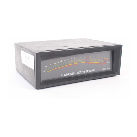
LOUDNESS MONITOR
LOUDNESS MONITOR
RELATIVE LOUDNESS
TO PEAK MODULATION
RELATIVE LOUDNESS TO PEAK MODULATION
Also covers Models 10-A(B), 12-A(B), 20-A(B), and 21-A(B)
DORROUGH ELECTRONICS
Woodland Hills, CA 91364
DORROUGH
Model 40-A
DORROUGH
Model 40-B
5221 Collier Place
(818) 999-1132
MODEL 40-A
MODEL 40-B
Advertisement
Table of Contents

Summary of Contents for Dorrough 40-A
- Page 1 Technical Instruction Manual DORROUGH LOUDNESS MONITOR Model 40-A LOUDNESS MONITOR MODEL 40-A DORROUGH RELATIVE LOUDNESS TO PEAK MODULATION Model 40-B MODEL 40-B RELATIVE LOUDNESS TO PEAK MODULATION Also covers Models 10-A(B), 12-A(B), 20-A(B), and 21-A(B) DORROUGH ELECTRONICS 5221 Collier Place...
- Page 2 INTRODUCTION Today’s audio requires careful attention to precise level control. The con- sumer now has audio playback systems that stretch the limits of program dynamics. With all this new equipment, the modern listener is able to hear subtle differences in level and distortion within program material and make critical program choices based on the quality of sound.
-
Page 3: Loudness Meter
Material with or without compression can easily be matched for the same listening level. Each DORROUGH Loudness Monitor features Right and Left inputs for use in stereo mixing applications. With one instrument, the operator can easily see the stereo mix and avoid the classic in-phase/out-of-phase problem. - Page 4 Unpacking Your DORROUGH Loudness Monitor was carefully packed at the factory. Take a moment to examine the unit for any signs of shipping damage. If damage is evident, retain the carton and notify the transit carrier and your local distributor about your claim.
- Page 5 DORROUGH ELECTRONICS USA WOODLAND HILLS, CA 91364 Recessed AC Cord Input Gain Controls Power Switch VR13 (L) and VR14 (R) Fig. 1. Back panel of DORROUGH Loudness Monitor, Model 40-A or Model 40-B. Mono Stereo L Stereo R Input Input Input Fig.
- Page 6 Mounting Considerations The DORROUGH Loudness Monitor is available with or without a case, and is manufactured in several versions to accommodate differing customer needs. For example, "A" Type models are the standard Loudness Monitors, while "B" Type models measure Relative Loudness to Peak Modulation (see front cover).
- Page 7 CUSTOMER'S PANEL MODEL 10-A(B) OPENING (single console or panel mount meter) 4.250 " 2.00 " 2.50 " (METER CLEARANCE BEHIND PANEL) (5.5 " maximum depth) 5.000 " (METER CLEARANCE BEHIND PANEL) (a) Model 10-A(B) panel mount specifications. CUSTOMER'S PANEL MODEL 12-A(B) OPENING (dual console or panel mount meter) 2.00 "...
- Page 8 CUSTOMER'S PANEL BEZEL WINDOW PCB MOUNT to 110 VAC METER ELECTRONICS AUDIO INPUTS 1. Install "jacking screws" into WINDOW so that tip of each screw is flush with far side of WINDOW. 2. Insert BEZEL through panel and hold in place by hand.
- Page 9 Field Alignment section. Applications DORROUGH Loudness Monitors can be used in a number of applications, as shown in Fig. 7 through Fig. 13, including: Telephone/Transmission, AM Mono Broadcast, Analog/Digital Tape Saturation Monitor, Sum & Difference Monitor, Stereo Television Broadcast, Disk Mastering, and Sound Reinforce- ment.
- Page 10 Most stations use an "A" Type DORROUGH Loudness Monitor to monitor the "unprocessed" Transmitter signal and either an "A" or B" Type DORROUGH Loudness Monitor to verify the Off-Air signals in real time. The "B" Type Monitor is the preferred instrument for verifying peak headroom.
- Page 11 Fig. 13. Sound Reinforcement Applications. An "A" Type DORROUGH Loudness Monitor can be utilized to verify phase integrity of signal pairs feeding a bank of power amplifiers. In addition, a "B" Type DORROUGH Loudness Monitor can be used (with bridging resistors) to monitor the...
- Page 12 CIRCUIT THEORY The circuits that make up the DORROUGH Loudness Monitor (and Relative Loudness to Peak Modulation meter) are grouped onto two circuit boards: an Input Signal Processing Board (including Power Supply), and a Bar and Peak Driver Circuit Board.
- Page 13 All adjustments for the alignment of the LED display are located on the Input Signal Processing Board. To gain access to these controls (40-A and 40-B Models), the instrument is placed bottom-side-up and the six screws are removed.
- Page 14 0 dB (A) +5 dB (A) -25 dB (A) +14 dB (A) -11 dB (B) -6 dB (B) +3 dB (B) -36 dB (B) LED DRIVER BOARD Fig. 15. Simplified view of key alignment components on Model 40-A (40-B) circuit boards.
- Page 15 "B" Type Monitor Alignment Procedure 1. Connect the output from a test oscillator to the meter’s left input termi- nals (see Fig. 1 ). 2. Feed a 1000 Hz sine-wave, at a reference level of “0” dB, into the meter. 3.
- Page 16 VR49 VR48 VR44 VR46 VR14 VR13 VR49 VR48 VR44 VR46 VR14 VR13 +R -R -15 +15 POWER SUPPLY BOARD INTERFACE BOARD (CUSTOMER'S POWER SUPPLY) VR49 VR48 VR44 VR46 VR14 VR13 SIGNAL BOARD 0 dB (A) +5 dB (A) -11 dB (B) -6 dB (B) - 25 dB (A) +14 dB (A)
- Page 17 VR49 VR48 VR44 VR46 VR14 VR13 VR49 VR48 VR44 VR46 VR14 VR13 +R -R +R -R POWER SUPPLY BOARD VR49 VR48 VR44 VR46 VR14 VR13 VR49 VR48 VR44 VR46 VR14 VR13 2 SIGNAL BOARDS 0 dB (A) 0 dB (A) +5 dB (A) +5 dB (A) -11 dB (B)
- Page 18 VR49 VR48 VR46 VR44 VR14 VR13 +R -R POWER SUPPLY BOARD VR49 VR48 VR46 VR44 VR14 VR13 DS3 DS4 SIGNAL BOARD -25 dB (A) 0 dB (A) +5 dB (A) +14 dB (A) -6 dB (B) -36 dB (B) +3 dB (B) -11 dB (B) LED DRIVER BOARD Fig.
- Page 19 NOTES...
Need help?
Do you have a question about the 40-A and is the answer not in the manual?
Questions and answers