Table of Contents
Advertisement
Quick Links
Advertisement
Table of Contents

Related Manuals for ASTRO WM-3014


Summary of Contents for ASTRO WM-3014
- Page 1 HD/SD 6-inch LCD Waveform Monitor WM-3014 Instruction Manual Ver.1.00...
-
Page 3: Instruction Manual
HD/SD 6-inch LCD Waveform Monitor WM-3014 Instruction Manual 2006.8 Ver.1.00 ASTRODESIGN,Inc... -
Page 5: Table Of Contents
CONCERNING THE WM-3014........................1 Outline of WM-3014 ............................. 1 Chapter 2 PARTS AND THEIR FUNCTIONS ......................3 WM-3014 front panel view and parts ......................3 WM-3014 rear panel view and parts ......................6 Chapter 3 OPERATION............................... 9 Connection procedure ..........................9 Usage ................................. - Page 6 3.4.4.5 CURSOR setting screen....................38 3.4.4.6 SETTING mode setting screen ..................39 3.4.4.7 Color setting screen....................41 3.4.5 VECTOR mode........................... 42 3.4.5.1 Regular screen ......................42 3.4.5.2 VECTOR mode setting screen...................44 3.4.5.3 Color setting screen....................45 3.4.6 STATUS mode ..........................46 3.4.6.1 Regular screen ......................46 3.4.6.2 Color setting screen....................47 3.4.7...
-
Page 7: Contents
CONTENTS Chapter 6 MAINTENANCE AND OTHER PROCEDURES..................81 When the monitor does not operate properly..................... 81 When trouble or malfunctioning occurs......................81... -
Page 8: Introduction
INTRODUCTION Thank you very much for purchasing this model WM-3014 HD LCD waveform monitor. This manual contains the procedures to be followed to operate the WM-3014, the checkpoints and precautions to be observed, and so on. Improper handling may result in malfunctioning. Before using the WM-3014, please read through these instructions to ensure that you will operate the monitor correctly. -
Page 9: Concerning Foreign Matter
INTRODUCTION Concerning foreign matter Do not spill liquids inside the monitor or drop inflammable objects or metal parts into it. Operating the monitor under these conditions may cause a fire, electric shocks and/or malfunctioning. CAUTION Concerning the power supply Use a supply voltage within the range of DC 10V to 18V ±5% for the monitor. In order to avoid malfunctioning and trouble, it is recommended that the accessory AC/DC adapter be used. -
Page 10: Concerning Impact
Handle the liquid crystal protective panel carefully. Carefully wipe off any fingerprints or dirt on the liquid crystal protective panel with a cleaning agent used to clean office automation equipment, for example. Rubbing the panel with too much force may mark or damage the panel. -
Page 11: Concerning Problems Due To The Nature Of Liquid Crystal
INTRODUCTION Concerning problems due to the nature of liquid crystal The following minor problems may occur due to the nature of liquid crystal. The liquid crystal's response time, brightness and colors may vary depending on the ambient temperature. Depending on what is displayed, unevenness in the brightness, flicker, vertical stripes and/or very small flecks may appear. - Page 12 viii...
-
Page 13: Concerning The Wm-3014
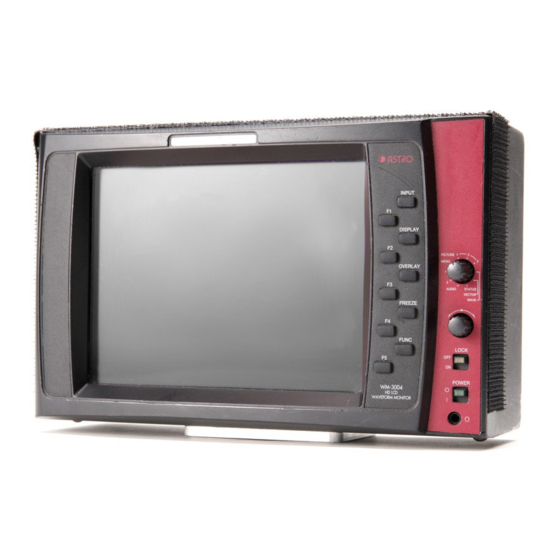
CONCERNING THE WM-3014 The WM-3014 is a compact, lightweight and portable LCD waveform monitor which comes in handy for monitoring the pictures being shot during live broadcasts, on location or in studios. The camera battery is supported as the power supply so that pictures, waveforms and sound can now be monitored even in locations where it would be difficult to carry in equipment. - Page 14 Single-action operation for selecting input channels, partial display/non-display of information, picture overlay and freeze/update using the switches on the front panel Many different display modes available Picture, waveform, vector, audio level meter, audio vector mode, multi display and picture waveform simultaneous display modes Compare mode provided Frozen images and the current images can be displayed for the purposes of comparison.
-
Page 15: Chapter 2 Parts And Their Functions
PARTS AND THEIR FUNCTIONS WM-3014 front panel view and parts PRESET MENU PICTURE MULTI AUDIO STATUS VECTOR WAVE OPE LOCK POWER WM-3014 HD LCD WAVEFORM MONITOR Fig. 2.1 WM-3014 front panel view... - Page 16 Table 2.1 Front panel parts Part Description of function POWER switch / LED This switch is used to turn the power ON and OFF. (Its LED lights up green while the power is supplied.) LOCK switch / LED This switch is used to lock the panel switches and save the settings simultaneously. Wait appears at the bottom right of the screen while the settings are being saved.
- Page 17 Chapter 2 PARTS AND THEIR FUNCTIONS P1 switch Operations in modes other than the freeze mode P2 switch These are the preset switches. They are used to save data in, and load data from, the P3 switch memory space with the number corresponding to the current setting. When a switch is P4 switch held down, the current setting is saved in the switch.
-
Page 18: Wm-3014 Rear Panel View And Parts
WM-3014 rear panel view and parts Fig. 2.2 WM-3014 rear panel view... - Page 19 Chapter 2 PARTS AND THEIR FUNCTIONS Table 2.2 Names of rear panel parts Part Description of function Power socket (*1) Cannon connector, DC power input socket (GND: pin 1; DC IN: pin 4). SDI IN Ach HD-SDI signal input connector. SDI IN Bch HD-SDI signal input connector.
- Page 20 *2: TALLY connector (no.9 in rear panel view) Pin No. Function TALLY 2(G) PRESET 1 PRESET 2 PRESET 3 TALLY 1(R) PRESET 4 PRESET 5 When GND and pin 2 are shorted, the green tally lamp lights; when GND and pin 7 are shorted, the red tally lamp lights. Details on the PRESET pins are provided below.
-
Page 21: Chapter 3 Operation
Check the shapes of the connector and socket before proceeding with the connections. Usage A protective film is adhered to the surface of the LCD panel. Peel it off before using the WM-3014. After checking the connections, turn on the power using the POWER switch on the front panel of the WM-3014. -
Page 22: Concerning The Screens
Concerning the screens This section describes the screen displays of the WM-3014 and the setting procedures. Regular screen PRESET MENU PICTURE MULTI AUDIO STATUS VECTOR WAVE OPE LOCK POWER WM-3014 HD LCD WAVEFORM MONITOR... - Page 23 The time elapsed since the last error was found is displayed here. P1, P2, W, V, ST, LAST A, ML, MN The time elapsed after the WM-3014 was started up or after the error count P1, P2, W, V, ST, TIME was reset is displayed here.
- Page 24 Picture mode...
- Page 25 Chapter 3 OPERATION Item Description Display modes This indicates whether the filter is ON or OFF. P1, P2 Filter This indicates whether monochrome is ON or OFF. P1, P2 Mono This indicates the color temperature of the liquid crystal which has been P1, P2 6500K set.
- Page 26 Other modes Item Description Display modes This indicates the waveform display method. YPbPr This indicates the parade display or overlay display for the waveforms. Parade Overlay This indicates the sweep 1H/2H/1F/2F switching. This indicates the magnification ratio. M×1 M×2 M×4 This indicates the gain magnification rate.
- Page 27 Chapter 3 OPERATION Color adjustment mode Item Description Display modes This indicates the color of the characters. P1, P2, P3, W, V, Information ST, A, MN This indicates the color of the markers. P1, P2, P3 Marker This indicates the color of the cursors. W, V, ST Cursor This indicates the color and brightness of the waveforms.
-
Page 28: Operation
Operation This section describes the WM-3014 screen displays. Descriptions of each mode are given in the following sections. PICTURE1 mode (refer to section 3.4.1) PICTURE2 mode (refer to section 3.4.2) PICTURE3 mode (refer to section 3.4.3) WAVEFORM mode (refer to section 3.4.4) VECTOR mode (refer to section 3.4.5) -
Page 29: Picture1 Mode
MENU PICTURE MULTI AUDIO STATUS VECTOR WAVE OPE LOCK POWER WM-3014 HD LCD WAVEFORM MONITOR [Description of operations] Switch Description of function FUNC switch Use this to return to the previous screen. F1 switch Use this to display the brightness setting screen. (Refer to section 3.2.1.2.) -
Page 30: Brightness Setting Screen
MENU PICTURE MULTI AUDIO STATUS VECTOR WAVE OPE LOCK POWER WM-3014 HD LCD WAVEFORM MONITOR [ Description of operations ] Switch Description of function FUNC switch Use this to return to the function screen. (Refer to section 3.4.1.1.) F1 switch Use this to adjust the brightness value by turning the adjustment dial. -
Page 31: Contrast Setting Screen
MENU PICTURE MULTI AUDIO STATUS VECTOR WAVE OPE LOCK POWER WM-3014 HD LCD WAVEFORM MONITOR [ Description of operations ] Switch Description of function FUNC switch Use this to return to the function screen. (Refer to section 3.4.1.1.) F1 switch Use this to adjust the contrast value by turning the adjustment dial. -
Page 32: Chroma Setting Screen
〈〈 Functions 〉〉 The input images are displayed, and the following image adjustments are performed on this screen. Pb (Cb) Pr (Cr) 〈〈 Screen 〉〉 PRESET MENU PICTURE MULTI AUDIO STATUS VECTOR WAVE OPE LOCK POWER WM-3014 HD LCD WAVEFORM MONITOR... - Page 33 Chapter 3 OPERATION [ Description of operations ] Switch Description of function FUNC switch Use this to return to the function screen. (Refer to section 3.4.1.1.) F1 switch Use this to adjust the chroma value by turning the adjustment dial. Variable range: 0.0% to 200.0% Chroma When the adjustment dial is pressed, the chroma value is returned to the initial value.
-
Page 34: Gamma Setting Screen
MENU PICTURE MULTI AUDIO STATUS VECTOR WAVE OPE LOCK POWER WM-3014 HD LCD WAVEFORM MONITOR [ Description of operations ] Switch Description of function FUNC switch Use this to return to the function screen. (Refer to section 3.4.1.1.) F1 switch Use this to adjust the Y-gamma value by turning the adjustment dial. -
Page 35: Other Image Setting Screen
The input images are displayed, and the following image adjustments are performed on this screen. Peaking Filter Color temperature Mask Half mask 〈〈 Screen 〉〉 PRESET MENU PICTURE MULTI AUDIO STATUS VECTOR WAVE OPE LOCK POWER WM-3014 HD LCD WAVEFORM MONITOR... - Page 36 [ Description of operations ] Switch Description of function FUNC switch Use this to return to the function screen. (Refer to section 3.4.1.1.) F1 switch Use this to adjust the peaking value by turning the adjustment dial. Variable range: OFF, ON (1 to 100) Peaking When the adjustment dial is pressed, the peaking value is returned to the initial value.
-
Page 37: Color Setting Screen
MENU PICTURE MULTI AUDIO STATUS VECTOR WAVE OPE LOCK POWER WM-3014 HD LCD WAVEFORM MONITOR [ Description of operations ] Switch Description of function FUNC switch Use this to return to the previous screen. F1 switch Use this to select the color (any of 63 colors) of the characters by turning the adjustment dial. -
Page 38: Pictuer2 Mode
Note: With the 525i/60 and 625i/50 formats, the 4:3, 13:9 and 14:9 markers are not displayed. Furthermore, if there are no input signals and AUTO has been selected for the format, the 1080 marker is displayed. 〈〈 Screen 〉〉 PRESET MENU PICTURE MULTI AUDIO STATUS VECTOR WAVE OPE LOCK POWER WM-3014 HD LCD WAVEFORM MONITOR... - Page 39 Chapter 3 OPERATION [ Description of operations ] Switch Description of function FUNC switch No function. F1 switch Use this to set monochrome to ON or OFF. When monochrome is set to ON, Green, Blue and Red are set to ON. Mono F2 switch Use this to display or not display the green of the input images.
-
Page 40: User Marker Setting Screen
MENU PICTURE MULTI AUDIO STATUS VECTOR WAVE OPE LOCK POWER WM-3014 HD LCD WAVEFORM MONITOR [ Description of operations ] Switch Description of function FUNC switch Use this to return to the regular screen. (Refer to section 3.4.2.1.) F1 switch Use this to adjust the horizontal marker value by turning the adjustment dial. -
Page 41: Color Setting Screen
MENU PICTURE MULTI AUDIO STATUS VECTOR WAVE OPE LOCK POWER WM-3014 HD LCD WAVEFORM MONITOR [ Description of operations ] Switch Description of function FUNC switch Use this to return to the regular screen. (Refer to section 3.4.2.1.) F1 switch Use this to select the color (any of 63 colors) of the characters by turning the adjustment dial. -
Page 42: Picture3 Mode
MENU PICTURE MULTI AUDIO STATUS VECTOR WAVE OPE LOCK POWER WM-3014 HD LCD WAVEFORM MONITOR [ Description of operations ] Switch Description of function FUNC switch No function. F1 switch Use this to set the H Delay to ON or OFF. -
Page 43: Color Setting Screen
MENU PICTURE MULTI AUDIO STATUS VECTOR WAVE OPE LOCK POWER WM-3014 HD LCD WAVEFORM MONITOR [ Description of operations ] Switch Description of function FUNC switch Use this to return to the regular screen. (Refer to section 3.4.3.1.) F1 switch Use this to select the color (any of 63 colors) of the characters by turning the adjustment dial. -
Page 44: Waveform Mode
PRESET MENU PICTURE MULTI AUDIO STATUS VECTOR WAVE OPE LOCK POWER WM-3014 HD LCD WAVEFORM MONITOR [ Description of operations ] Switch Description of function FUNC switch Use this to return to the previous screen. Adjustment dial No function. F1 switch Use this to set the display to the DISPLAY setting screen. -
Page 45: Display Setting Screen
MENU PICTURE MULTI AUDIO STATUS VECTOR WAVE OPE LOCK POWER WM-3014 HD LCD WAVEFORM MONITOR [ Description of operations ] Switch Description of function FUNC switch Use this to return to the function screen. (Refer to section 3.4.4.1.) F1 switch... -
Page 46: Sweep Setting Screen
The waveforms are displayed, and the following settings can be performed on this screen. 1H, 2H, 1F or 2F display switching Line select function (with 1H, 2H) 〈〈 Screen 〉〉 PRESET MENU PICTURE MULTI AUDIO STATUS VECTOR WAVE OPE LOCK POWER WM-3014 HD LCD WAVEFORM MONITOR... - Page 47 Chapter 3 OPERATION [ Description of operations ] Switch Description of function FUNC switch Use this to return to the function screen. (Refer to section 3.4.4.1.) F1 switch Use this to set the 1H display. F2 switch Use this to set the 2H display (with the interlacing or segmented frame format).
-
Page 48: Gain/Mag Setting Screen
The waveforms are displayed, and the following settings can be performed on this screen. Gain (×0.03 to ×7.97), MAG (1×, 2× or 4×) setting Scroll functions 〈〈 Screen 〉〉 PRESET MENU PICTURE MULTI AUDIO STATUS VECTOR WAVE OPE LOCK POWER WM-3014 HD LCD WAVEFORM MONITOR... - Page 49 Chapter 3 OPERATION [ Description of operations ] Switch Description of function FUNC switch Use this to return to the function screen. (Refer to section 3.4.4.1.) Turning the adjustment dial When The Gain Setting Is Fixed No function. ×1 / ×5 When the gain setting is variable Turn the dial to set the magnification rate of the gain.
-
Page 50: Cursor Setting Screen
MENU PICTURE MULTI AUDIO STATUS VECTOR WAVE OPE LOCK POWER WM-3014 HD LCD WAVEFORM MONITOR [ Description of operations ] Switch Description of function FUNC switch Use this to return to the function screen. (Refer to section 3.4.4.1.) Adjustment dial Use this to move the cursor horizontally or vertically. -
Page 51: Setting Mode Setting Screen
The waveforms are displayed, and the following settings can be performed on this screen. Waveform display YPbPr/GBR/RGB switching V Ancillary (Wave) and H Blanking switching Scale switching Filter selection 〈〈 Screen 〉〉 PRESET MENU PICTURE MULTI AUDIO STATUS VECTOR WAVE OPE LOCK POWER WM-3014 HD LCD WAVEFORM MONITOR... - Page 52 [ Description of operations ] Switch Description of function FUNC switch Use this to return to the function screen. (Refer to section 3.4.4.1.) Adjustment dial No function. F1 switch Use this to switch between YPbPr, GBR and RGB for the waveform display. Waveform YPbPr Waveform GBR Waveform RGB...
-
Page 53: Color Setting Screen
MENU PICTURE MULTI AUDIO STATUS VECTOR WAVE OPE LOCK POWER WM-3014 HD LCD WAVEFORM MONITOR [ Description of operations ] Switch Description of function FUNC switch Use this to return to the previous screen. F1 switch Use this to select the color (any of 63 colors) of the characters by turning the adjustment dial. -
Page 54: Vector Mode
In regard to the PAL signals, however, the waveforms of the 3 lines each at the start and end of the video signals will be more disturbed than in actuality. 〈〈 Screen 〉〉 PRESET MENU PICTURE MULTI AUDIO STATUS VECTOR WAVE OPE LOCK POWER WM-3014 HD LCD WAVEFORM MONITOR... - Page 55 Chapter 3 OPERATION [ Description of operations ] Switch Description of function FUNC switch Use this to switch the display to the VECTOR mode setting screen. (Refer to section 3.4.7.2.) Turning the adjustment dial When the gain setting is fixed No function.
-
Page 56: Vector Mode Setting Screen
MENU PICTURE MULTI AUDIO STATUS VECTOR WAVE OPE LOCK POWER WM-3014 HD LCD WAVEFORM MONITOR [ Description of operations ] Switch Description of function FUNC switch Use this to display the regular screen. (Refer to section 3.4.7.1.) Adjustment dial No function. -
Page 57: Color Setting Screen
MENU PICTURE MULTI AUDIO STATUS VECTOR WAVE OPE LOCK POWER WM-3014 HD LCD WAVEFORM MONITOR [ Description of operations ] Switch Description of function FUNC switch Use this to return to the previous screen. F1 switch Use this to select the color (any of 63 colors) of the characters by turning the adjustment dial. -
Page 58: Status Mode
Line MULTI Sample AUDIO STATUS VECTOR WAVE OPE LOCK YCRCE: 0000000 LAST: 00:00:00 POWER WM-3014 PCRCE: 0000000 TIME: 00:00:00 HD LCD WAVEFORM MONITOR [ Description of operations ] Switch Description of function FUNC switch (Not used) Turning the adjustment dial Turn the dial to increment or decrement the lines or samples of the status displayed. -
Page 59: Color Setting Screen
Cursor OPE LOCK YCRCE: 0000000 LAST: 00:00:00 Exit PCRCE: 0000000 TIME: 00:00:00 VITC:00:00:00:00 POWER WM-3014 HD LCD WAVEFORM MONITOR [ Description of operations ] Switch Description of function FUNC switch Use this to return to the regular screen. (Refer to section 3.4.6.1.) -
Page 60: Audio Mode
MENU PICTURE MULTI AUDIO STATUS VECTOR WAVE OPE LOCK POWER WM-3014 HD LCD WAVEFORM MONITOR [ Description of operations ] Switch Description of function FUNC switch Use this to select the audio vector screen. (Refer to section 3.4.8.2.) F1 switch Use this to adjust the volume level by turning the adjustment dial. -
Page 61: Audio Vector Screen
MULTI AUDIO Output R STATUS VECTOR WAVE OPE LOCK POWER WM-3014 HD LCD WAVEFORM MONITOR [ Description of operations ] Switch Description of function FUNC switch Use this to select the audio level meter screen. (Refer to section 3.4.8.1.) F1 switch Use this to adjust the volume level by turning the adjustment dial. -
Page 62: Color Setting Screen
When the OVERLAY switch is held down in the AUDIO mode, the following settings can be performed on this screen. Character color Scale color Audio level meter color Audio vector waveform color 〈〈 Screen 〉〉 PRESET MENU PICTURE MULTI AUDIO STATUS VECTOR WAVE OPE LOCK POWER WM-3014 HD LCD WAVEFORM MONITOR... - Page 63 Chapter 3 OPERATION [ Description of operations ] Switch Description of function FUNC switch Use this to return to the previous screen. F1 switch Use this to select the color (any of 63 colors) of the characters by turning the adjustment dial.
-
Page 64: Multi Mode
3.4.8 Multi mode In the multi mode, the DISPLAY, OVERLAY and F1 to F5 switches do not work when the multi mode 1 screen is selected; when the multi mode 2 screen is selected, only the OVERLAY switch does not work. * When composite signals are input, the data after the signals have been converted into component signals is displayed. - Page 65 Chapter 3 OPERATION [ Description of operations ] Switch Description of function FUNC switch Use this to display the multi mode 2 screen. (Refer to section 3.2.5.2.) F1 switch No function. F2 switch No function. F3 switch No function. F4 switch No function.
-
Page 66: Multi Mode 2 Screen
3.4.8.2 Multi mode 2 screen 〈〈 Functions 〉〉 The input images and waveforms can be displayed simultaneously. The following settings can be performed on this screen. Setting item What happens on multi mode 2 screen Scale color As set Cursor Not displayed Line select Invalid... -
Page 67: Preset Mode
MULTI AUDIO STATUS VECTOR WAVE OPE LOCK POWER WM-3014 HD LCD WAVEFORM MONITOR [ Description of operations ] Description of function P1 switch Use this to call the data stored in the P1 switch. If no data has been stored, the picture-only screen appears. -
Page 68: 3.4.10 Menu Mode
* When analog signals are input, the monitor will not operate properly unless the formats of the image signals and reference signals match. 〈〈 Screen 〉〉 PRESET MENU PICTURE MULTI AUDIO STATUS VECTOR WAVE OPE LOCK POWER WM-3014 HD LCD WAVEFORM MONITOR... - Page 69 The low power consumption function which involves turning off the backlight of the liquid Power Save Mode crystal display can be selected here. When the prescribed period elapses without performing any WM-3014 operations, the backlight of the liquid crystal display is turned off, and the low power consumption mode is established.
-
Page 70: Color Setting Screen
MENU PICTURE MULTI AUDIO STATUS VECTOR WAVE OPE LOCK POWER WM-3014 HD LCD WAVEFORM MONITOR [ Description of operations ] Switch Description of function FUNC switch Use this to return to the regular screen. (Refer to section 3.4.10.1.) F1 switch Use this to select the color (any of 63 colors) of the characters by turning the adjustment dial. -
Page 71: 3.4.11 Compare Mode
Chapter 3 OPERATION 3.4.11 Compare mode 3.4.11.1 Outline 〈〈 Outline 〉〉 The compare mode is established by pressing P1, P2, P3 or P4 in the freeze status. This mode is useful for comparing the current data against the freeze data in different ways. 〈〈... -
Page 72: Compare Mode 1
3.4.11.2 Compare mode 1 〈〈 Outline 〉〉 In this mode, the picture screens of the freeze data and current data are superimposed onto each other, and displayed. 〈〈 Functions 〉〉 H Delay V Delay 〈〈 Screen 〉〉 FUNC OPE LOCK [ Description of operations ] Switch Description of function... -
Page 73: Compare Mode 2
LPF (Vect) switching * When composite signals are input, the data after the signals have been converted into component signals is displayed. 〈〈 Screen 〉〉 PRESET MENU PICTURE MULTI AUDIO STATUS VECTOR WAVE OPE LOCK POWER WM-3014 HD LCD WAVEFORM MONITOR... - Page 74 [ Description of operations ] (Regular screen) Switch Description of function FUNC switch Use this to set the display to the VECTOR mode setting screen. Turning the adjustment dial When the gain setting is fixed No function. Fix ×1 / ×5 When the gain setting is variable Turn the dial to set the magnification rate of the gain.
-
Page 75: Compare Mode 3
Chapter 3 OPERATION 3.4.11.4 Compare mode 3 〈〈 Functions 〉〉 In this mode, the waveforms of the images for the freeze data and current input data are displayed simultaneously side by side at the left and right. The settings are as shown below. Setting item What happens on multi mode 2 screen Scale color... -
Page 76: Compare Mode 4
3.4.11.5 Compare mode 4 〈〈 Functions 〉〉 In this mode, the freeze data and current input data are displayed simultaneously. The images are displayed simultaneously side by side at the left and right. One of the Y/Pb/Pr (or G/B/R) waveforms is selected, superimposed and displayed. The settings are as shown below. -
Page 77: Chapter 4 Main Specifications
MAIN SPECIFICATIONS Input formats Format Frame Active Total Line Samples per Samples per Scanning Active Line Total Line Rate Line Line Frequency (Hz) (kHz) Frame Frame 1035i/60 1035i/59.94 30/1.001 1035 1125 33.72 1920 2200 1035i/60 1035 1125 33.75 1920 2200 1080i/60 1080i/59.94 30/1.001... -
Page 78: Input Signal Systems
Input signal systems SDI input Specification specification SDI input HDTV BTA S-004B complied with,SMPTE 292M complied with, NRZI SDI signal SDTV SMPTE 259M complied with, NRZI SDI signal Field (frame) frequency, 60.00/59.94 [Hz], etc. automatically tracked Automatic tracking of input format enabled Analog input Specification specification... -
Page 79: Headphones Output Format
Chapter 4 MAIN SPECIFICATIONS Headphones output format 50mW ± 5% (32Ω/1kHz) Maximum output Frequency response 100Hz to 20kHz (0dB to -3dB) -
Page 80: Concerning The Adjustment Values
Concerning the adjustment values Brightness The offset level of the luminance signal can be varied in the range of -50.00 to +50.00%. This applies to the G brightness, B brightness and R brightness as well. Display level +50% Contrast The level of the luminance signal can be varied in the range of 0.0 to 200.0%. This applies to the G contrast, B contrast and R contrast as well. - Page 81 Chapter 4 MAIN SPECIFICATIONS Chroma, Pb (Cb), Pr (Cr) The level of the chrominance signals can be varied in the range of 0.0 to 200.0%. Display level 200% 100% -109 -100 Input level -100 -109...
- Page 82 Precautions for chroma boost function The figure below shows the relationship between the Pb and Pr input signals and the display level when the chroma boost function (×3) has been set to ON. Bear in mind that if the result of multiplying the chroma signal value by 3 exceeds ±109%, a limit will be imposed at ±109%.
-
Page 83: Concerning The 4:3 Function
Chapter 4 MAIN SPECIFICATIONS Concerning the 4:3 function With a resolution of 1920 × 1080 pixels An image with an area of 1440 × 1080 pixels near the center is cut out from the image area and displayed with 1024 × 768 pixels. The same processing as with 1920 ×... - Page 84 CAUTION Explanation of displays ••• This indicates the image. ••• This indicates the liquid crystal screen. ••• This indicates an image displayed in the 4:3 format.
-
Page 85: Concerning The Audio Level Meter
Chapter 4 MAIN SPECIFICATIONS Concerning the audio level meter The audio level meter indicates the level as follows. Audio standards: BTA S-006B and SMPTE 272M-A 0 (Unit: dB) or less or less or less or less or less or less or less or less or less... -
Page 86: Settings At Initialization
Settings at initialization The settings established when the WM-3014 was shipped from the factory and when they are initialized are listed below. Common setting items The settings for the following items are the same whether for SDI A, SDI B, Analog or VBS channels. -
Page 87: Setting Items By Channel
Chapter 4 MAIN SPECIFICATIONS Setting item Setting/adjustment range Initial value SWEEP 1H, 2H, 1F, 2F GAIN (WAVEFORM mode) ×0.03 to ×7.97 ×1 CTR Pos. C Aligned, Center Aligned H cursor ON, OFF V cursor ON, OFF MOVE BASE, OFFSET, TRACK BASE Waveform YPbPr. - Page 88 Setting item Setting/adjustment range Initial value Blue ON, OFF ON, OFF Volume 0 to 255 Output 1CH to 16CH L:1CH R:2CH Format All 15 types AUTO Analog All 13 types AUTO COMPOSITE All 2 types AUTO Int, Ref HD, Ref BB (525), Reference Ref BB (625) Analog...
-
Page 89: General Specifications
Chapter 4 MAIN SPECIFICATIONS General specifications Table 4.1 Operating environment and ratings for WM-3014 (main unit) Operating temperature range 0 to 40 °C Operating humidity range 30 to 80%RH (ambient temperature must be in the 0 to 40 °C range... -
Page 90: 4.10 Outline Drawings
SDI IN CH B P IN MONITOR OUT P IN TALLY REF IN DC IN 12V 1 GND 4 +12V MODEL ; SER.No ; MADE IN JAPAN PRESET MENU PICTURE MULTI AUDIO STATUS VECTOR WAVE OPE LOCK POWER WM-3014 HD LCD WAVEFORM MONITOR... -
Page 91: Chapter 5 Standard And Optional Accessories
STANDARD AND OPTIONAL ACCESSORIES Standard accessories WM-3014 instruction manual 1 copy AC/DC adapter 1 pc M4 screws (for attaching rack-mounting fixtures) 4 pcs Clear bumpons 4 pcs... -
Page 93: When The Monitor Does Not Operate Properly
MAINTENANCE AND OTHER PROCEDURES When the monitor does not operate properly Symptom What is to be checked The image is not displayed properly. Has the correct format been set? Color Space (YPbPr/GBR) been set correctly? Has the input channel been set correctly? The front panel switches fail to operate. - Page 95 WM-3014 Instruction Manual NOTICE An incorrectly collated manual or a manual with missing pages will be replaced. All copyrights pertaining to this manual are the property of Astrodesign. This manual may not be used or copied in whole or in part without permission.
Need help?
Do you have a question about the WM-3014 and is the answer not in the manual?
Questions and answers