
Summary of Contents for Better Quick Dually
-
Page 1: Operators Manual
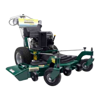
Operators Manual Quick Dually Mowers ™ Featuring the EZR™ Control System Better Outdoor Products, West Point Business Park 2595 Viceroy Drive Winston-Salem, North Carolina 27103 866-290-7295 BetterOutdoorProducts.com... -
Page 2: Introduction
Introduction • Danger signals an extreme hazard that will cause Thank you for purchasing one of our Quick Dually™ serious injury or death if you do not follow the series mowers. If this product does not work to your recommended precautions. -
Page 3: Table Of Contents
Table of Contents Introduction ..................................2 Safety ...................................... 6 Safety ....................................6 Safety Decals ..................................8 Product Overview .................................. 10 Controls ..................................... 10 Ignition Switch ................................... 10 Choke ....................................10 Throttle Control .................................. 10 ... - Page 4 Testing the Safety Interlock System ..........................14 Wheel Drive System ................................14 Blade Drive System ................................14 Quick™ Adjustments ................................15 Height of Cut ..................................15 Belt Guard Cover ................................16 Wheel Tracking .................................. 16 ...
- Page 5 Deck Drive Belt (BOP 10596 Gates 6945) 36” Models (BOP 10476 Gates 6951) 44” Models ........27 Deck Belt (BOP 10047 Gates 6868) 36” Models (BOP 10475 Gates 6882) 44” Models ..........27 Hydro Drive Belt (BOP 10706 Gates 6831) All Models ..................... 27 ...
-
Page 6: Safety
Safety properly. Do Not operate unless they are functioning Safety properly. Note: The addition of attachments made by other manufacturers that do not meet American National Operation • Never run an engine in an enclosed area. Standards Institute certification will cause noncompliance of this machine. - Page 7 • Always have an approved and fully charged fire The following list contains safety information specific extinguisher near your work area. to Better Outdoor Products™ and other safety • Wear personal eye protection when using information you must know. This product is capable compressed air for cleaning purposes.
-
Page 8: Safety Decals
Safety Decals Safety decals and instructions are easily visible to the operator and are located near any area of potential danger. Replace any decal that is damaged or lost. BetterOutdoorProducts.com... - Page 9 BetterOutdoorProducts.com...
-
Page 10: Product Overview
Product Overview Ignition Switch This switch is used to start the mower engine. Manual start engines have two positions: Run and Stop. Electric start engines have three positions: Start, Run and Stop. Choke Use the choke when starting a cold engine. Throttle Control The throttle controls engine RPM. -
Page 11: Hour Meter
Recommended Maintenance Schedule. Attachments/Accessories A selection of Better Outdoor Products™ approved attachments and accessories are available for use with the machine to enhance and expand its capabilities. Contact Better Outdoor Products™ for information on approved accessories. -
Page 12: Operation
Operation Adding Fuel Use Unleaded Regular Gasoline suitable for automotive use (85 octane minimum). Gasoline is harmful or fatal if swallowed. Long-term Important: Never use methanol, gasoline exposure to vapors can cause serious injury and containing methanol, or gasohol containing more illness. -
Page 13: Think Safety First
Moving Forward or Backward Think Safety First The throttle control regulates the engine speed as Carefully read all the safety instructions and decals measured in rpm (revolutions per minute). Place the in the safety section. Knowing this information could throttle control in the Run position for best help you or any bystanders avoid injury. -
Page 14: Pushing The Machine By Hand
Note: If the safety system does not operate as with the mower blades engaged. described above, contact Better Outdoor Products™ The safety interlock system is designed not to allow immediately. the engine to start unless the right motion control lever is in the neutral position. -
Page 15: Quick™ Adjustments
Quick™ Adjustments 4. Add/remove spacers to the bottom side of the fork Height of Cut for desired height of cut. See table below. 5. Install in reverse order and repeat on other fork. 1. Support front of deck with a jack stand Figure 7. 6. -
Page 16: Belt Guard Cover
Belt Guard Cover 1. Remove caster arm reinforcement strut knobs and rotate struts to the side Figure 11. Figure 13 3. Tighten jam nuts. Figure 11 2. Remove belt cover knobs and remove cover. 3. Reinstall in reverse order. Wheel Tracking The wheel tracking can be adjusted so that the machine will travel straight. -
Page 17: Maintenance
Changing the Oil (50hrs) 1. Start the engine and let it run five minutes. This warms the oil so it drains better. 2. Park the machine so that the rear of the machine is slightly lower to assure the oil drains completely. -
Page 18: Changing The Oil Filter (100Hrs)
Slowly pour approximately 80% of the specified oil Type: Champion® RCJ8Y or equivalent into the filler tube. Air Gap: 0.030 inch (0.75 mm) Check the oil level; refer to Checking the Engine Oil Removing the Spark Plug(s) Level. Slowly add the additional oil to bring it to the Full Disengage the PTO. -
Page 19: Installing The Spark Plug(S)
1. Center electrode insulator 2. Side electrode 3. Air gap (not to scale) Important: Always replace a spark plug(s) when it has a worn electrode, an oily film, or cracks in the porcelain. Check the gap between the center and side electrode (Figure 19). -
Page 20: Caster Fork (25 Hrs.)
Figure 22 Figure 23 Caster Fork (25 hrs.) 1. Remove caster forks (refer to height of cut adjustment). 2. Using a fine grit sandpaper, clean any rust or dirt from caster fork shafts and caster bearings. 3. Using a light lubricant (WD-40™), lubricate clean shafts. -
Page 21: Ezt Hydro
EZT Hydro Better Outdoor Products™ uses Hydro-Gear’s newest EZT line of sealed pump/motors utilizing one inch axles and a four lug pattern for easy mounting of wheel assembly. These units were developed for riding zero turn mowers and provide extreme durability in this application. -
Page 22: Troubleshooting
Troubleshooting Problem Possible Cause Corrective Action Engine will not start, starts 1. Fuel tank is empty. 1. Fill fuel tank with gasoline. hard, or fails to keep 2. Choke is not on. 2. Move the choke lever to choke running. 3. -
Page 23: Repair
1. This switch is included as a component of the blade engagement control cable. 2. Please refer to Blade Engagement control replacement. Battery (10799) All Quick Dually™ mowers are equipped with the latest assembled glass mat maintenance free battery. Figure 28 Battery terminals or metal tools could short against 4. -
Page 24: Starter Solenoid (10127)
4. Using a Phillips screwdriver and 7/16” wrench, Not touch any metal surface. remove solenoid Figure 31. 6. Install new battery in reverse order. Note: If your Quick Dually™ mower is going to be stored, we recommend using our “Smart” Charger (10697). Figure 31 5. -
Page 25: Motion Control Interlock Switch
Motion Control Interlock Switch Blade Engagement Control Cable (10081) 1. Remove the hairpin cotter Figure 32. 1. Disconnect the wiring plug from the safety switch under the PTO control Figure 34. Figure 32 2. Remove the clevis pin Figure 33. Figure 34 2. -
Page 26: Throttle Cable (10439) Kawasaki
6. Disconnect the spring from the clutch engagement arm Figure 37. Figure 39 4. Cut any cable ties and remove cable. Install in reverse order. Figure 37 Choke Cable (10440) Electric Start 7. Cut any cable ties and remove cable assembly. 8. -
Page 27: Deck Drive Belt (Bop 10596 Gates 6945) 36" Models (Bop 10476 Gates 6951) 44" Models
battery bracket to ensure cable does not come into 5. Install new belt in reverse order making sure that it contact with positive battery post. seats in all pulleys. Note: There is a decal on 36” and 44” decks that Deck Drive Belt (BOP 10596 Gates 6945) 36”... -
Page 28: Multi Disc Clutch (10579)
9. Slip belt off clutch and remove. 10. Install the new belt in reverse order making sure that it seats in all pulleys. Multi Disc Clutch (10579) 1. Remove deck drive belt (refer to Deck Drive Belt). 2. Lower mower deck to lowest position. 3. -
Page 29: Spindle Pulley (10251) (10252) (10483)
9. Install new spindle in reverse order. Figure 52 5. Using a 3/4” socket and wrench, remove idler arm Spindle Pulley (10251) (10252) (10483) bolt Figure 53. 1. See Spindle Replacement above. 2. 36 “ models have two single pulleys (10252) and one double pulley (10251). -
Page 30: Hydro Drive Axles Lh (10711), Rh(10712)
Figure 55 Figure 58 3. Using a 7/16” wrench, remove the starter cable 7. Remove transaxle drive belt (refer to Transaxle Figure 56. Drive Belt). 8. Remove clutch (refer to Clutch Replacement). 9. Using a 1/2” wrench and 1/2” socket, remove the four bolts holding the engine to the power unit. - Page 31 Figure 60 Figure 63 5. It is recommended to have two people for the 8. You should be able to lift up on the handlebars and remaining steps. Using a 9/16” wrench and 9/16” roll the machine off of the hydro assembly. Note: socket, remove the two bolts holding the swingarm Be careful that the dump valves are clear of the slots to the lower support Figure 61.
- Page 32 12. Using needle nose pliers, remove the cotter pin securing the brake yoke to the brake lever Figure Figure 67 15. Using a 9/16” wrench and 9/16” socket, and a 5/8” wrench and 5/8” socket, remove the bolts securing Figure 65 the hydro arm to hydro pump Figure 68.
-
Page 33: Wiring Schematics
Wiring Schematics BetterOutdoorProducts.com... - Page 34 BetterOutdoorProducts.com...
-
Page 35: Accessories
Accessories 4. Insert carriage bolt through hole in deck and through Mulching Kit (ACC-0013) 36” models hole in mulching kit Figure D. (ACC-0014) 44” models Support front of machine with jack stand Figure A. Figure D 5. Secure with flat washer, lock washer, and knob. Figure A 1. -
Page 36: Mulching Tips
3. Install new Gator blades making sure to keep bolt, lock washer, and blade washer in correct order Figure F. Bolt Lock washer Flat washer Figure Q 2. Attach mounting arms to the green slotted channel. 3. Adjust striping assembly left or right to center behind the mower. -
Page 37: Warranty
Owner’s Manual for the proper maintenance abuse, misuse, negligence, accidents, and normal schedule. Better™ can provide you with the wear. It does not cover incidental or consequential complete line of genuine parts and accessories costs such as transporting your equipment to and necessary to keep your machine running like new.
Need help?
Do you have a question about the Quick Dually and is the answer not in the manual?
Questions and answers