Advertisement
Advertisement
Table of Contents

Subscribe to Our Youtube Channel
Summary of Contents for OmniSite Crystal Ball
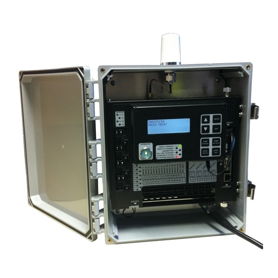
- Page 1 Crystal Ball User’s Guide Crystal Ball User’s Guide 494 S. Emerson Ave., Suite E, Greenwood, IN 46143 Telephone 317-885-6330 • support@omnisite.com 494 S. Emerson Ave., Suite E, Greenwood, IN 46143 www.omnisite.com Telephone 317-885-6330 • support@omnisite.com v. 2.0 www.omnisite.com v. 2.0...
-
Page 2: Limited Warranty
Limited Warranty If it appears within one (1) year from the date of delivery to Purchaser that any products or component parts do not conform exactly to the specifications and physical dimen- NOTICE sions referred to herein, and the Purchaser, at its expense, returns the product or com- ponent parts to the Seller together with a report of defects, the Seller shall review the inspection report and inspect the items and shall authorize, at its option, either the INSPECT CONTENTS IMMEDIATELY... -
Page 3: General Safety Instructions
WINGS™ (Wireless Information Network Gateway Standard) over a cellular network. The low cost of the OmniSite method makes remote monitoring very affordable, and allows our devices to operate on the 1. To reduce the risk of fire or shock hazard, connect OmniSite RTU GSM networks worldwide. - Page 4 “Phantom” antenna on top of your existing Look at the cellular signal strength LED on the Crystal Ball. If it is GREEN, you have a panel; then connect the antenna to the RTU using an OmniSite supplied coax jumper good signal, and can proceed with installation.
- Page 5 The default mode is for the cellular radio to remain powered on at all times when power is applied to the Crystal Ball to allow remote control from the web site. In low • This is a cellular device like a telephone, and has an associated monthly power mode, the radio is powered off after 1 minute of inactivity (see how to set low- cellular service fee.
-
Page 6: Wiring Diagrams
Wiring Diagrams Example - Monitoring Dry, Unpowered Contacts The Crystal Ball Field Terminal Strip L G N... - Page 7 Wiring Diagrams - Cont’d * Crystal Ball Analog Input Example Wiring 4-20mA Analog Inputs Impedence = 250 ohms ** 12VDC @ 80mA max, each input Jumper 3-Wire Device Jumper Field 2-Wire Loop Powered 4-20 mA Device Field SIGNAL Device 4-20 mA...
- Page 8 Wiring Diagrams - Cont’d Monitoring a Typical Pump Control Panel Crystal User User User selectable Reserved for Selectable Selectable Ball alarm or float Pump 1,2,3 Alarm Alarm Runtim e control inputs Input or Input or Pulse Accumulation Rain Counter Gauge Batter y Backed Dedicated Alarm Inputs...
- Page 9 Wiring Diagrams - Cont’d NC NO NO NC Using the Crystal Ball as a Pump Controller NC NO NO NC 120 VAC CONTROL CIRCUIT Crystal Ball User User DI-12 Reser ved for User selectable Selectable Selectable Pump 1,2,3 alarm or float...
- Page 10 7. Relay Outputs - Note that the Crystal Ball relay outputs are “pre-assigned: as this manual. Note: the diagram in this manual on P15 assumes your floats are pow- follows: ered by an external 120 VAC source. If not, and the Crystal Ball will be supplying the • Relay-1 Pump-1 power to floats, then wire your floats as show on page 10 of this manual titled “...
- Page 11 Quick Setup for the Pump Calculator • Relay-4 Spare-for custom use 1. The Crystal Ball has the ability to report the following calculations on up to (3) 8. Once your wiring connections are made, you HAVE TO enter the following setup pumps: parameters using the Crystal Ball local keypad: •...
- Page 12 Crystal Ball Field Input/Output Circuit Functionality Alternatively, these inputs can monitor and totalize pulses from a pulse output device at a max. rate of 30Hz (used to read flow and electric meters) INPUT DESCRIPTION (Inputs 8 thru 11) Connection of any “ON/OFF” style voltage signal in the range or (Inputs 1 thru 4) Connection of any “ON/OFF style”...
- Page 13 normally open contacts to correctly accumulate runtime NOTES (e.g. voltage is applied to input 12,13, or 14 when the respective pump is running) Analog inputs 1-4 Connection of any 4-20mA device signal allows remote monitoring and alarm set point notification. Relay outputs 1-4 Connect to automatic control circuit of pump motor starter to pro- vide automatic pump-up (drinking water applications) or pump-...
-
Page 14: Appendix A - Local Programming
- Pressing EXIT for 2 seconds will return the user to the main menu. - Pressing EXIT momentarily will return the user to the previous menu. NOTE: The Crystal Ball RTU must be disabled with the Intelligent ID key • While editing a value: before setup changes can be made. - Page 15 1) Sensors: (NONE, 4-20mA+FLT, 4-20mA, FLOATS; NONE) Crystal Ball Menu Tree 1)Pump Settings 3) Pump Control 2) # of Pumps: (00-03; 00) 3) Grease Cntrl %: (00-10; 00) 1) Need Help? Call OmniSite Ph. 317-885-6330 4) Alternate? (YES/NO; YES) Or go online: www.omnisite.com 5) Pump Scheme: (DOWN/UP;...
- Page 16 For each alarm, You have to answer these questions if you 11) INP 11 (1s-3600s; 5s) define the alarm want the Crystal Ball to calculate station flow, 12) Power Failure (1s-3600s; and the alarm and calculate pump GPM rate. 60s) time delay (i.e.
- Page 17 Crystal Ball Menu Tree 1) Maint. Key# (--/00-99) 1) Lst FOCC Rcvd (--/00-99) 2) Domain Name: rtu.omni-site.net 2) Battery (< 5.0=BAD/5.0 to 13.2V) 5) Diagnostics (cont’d) 5) Diagnostics 1) RTU Status 3) Domain IP Addr: 68.255.116.1 3) RTU Temp (-20.0 to 150.0F)
-
Page 18: Appendix B - Hardware Specification
Operating Temp. -20 to 150 F Storage Temp. -20 to 180 F In the unlikely event that you should have a problem with your new OmniSite prod- Humidity 5-95% RH, non-condensing uct, the following replacement parts are available for purchase from... -
Page 19: Appendix D - Troubleshooting Chart
OmniSite distributor in your area. alarms, and no control VDC power source. panel lights are • For the location of an OmniSite repair service center in your area call OmniSite illuminated. at (317) 885-6330 • For information on purchasing an OmniSite Maintenance Agreement or... - Page 20 “false” monitoring equipment. It is only “as If they are, check on the Crystal Ball alarms, and when I alarms. front panel to see that the associated good” as the equipment it is monitor-...
-
Page 21: Appendix E - Location For Setting Software Parameters
Appendix E - Location for Setting Software Parameters Trouble Probable Cause Remedy Process Unit Website First, check to see that your Relay Outputs Wiring Error relay output is wired EXACTLY Enter input time delays √ Not Working as shown previously in this manual. - Page 22 NOTES NOTES...
Need help?
Do you have a question about the Crystal Ball and is the answer not in the manual?
Questions and answers